Project 2
1)
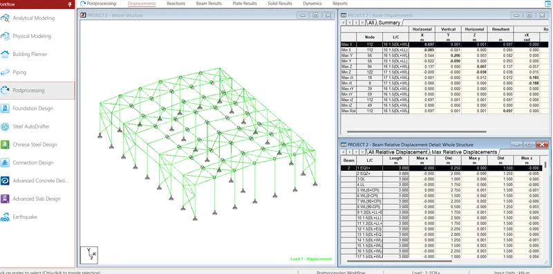
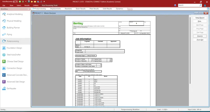
Aim:
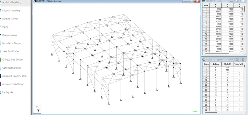
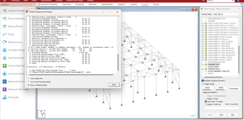
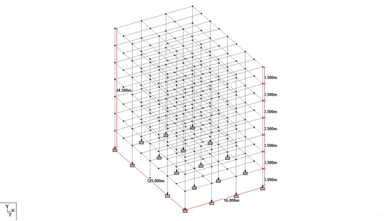
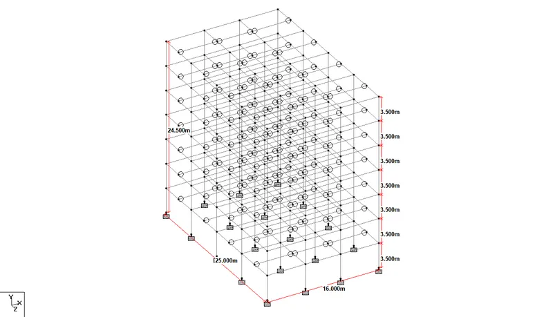
To design a multi-story Residential Building located in Bangalore using STAAD Pro Connect Edition.
Procedure:
Unit weight of the materials
Reinforced Cement Concrete = 25kNmm3���3
Plain Cement Concrete = 24kNmm3���3
Cement Concrete Screed = 20kNmm3���3
Cement Masonry Units = 22kNmm3���3
Structural Steel = 78.5kNmm3���3
Soil = 18kNmm3���3
Dead Load
Floor slab
Slab weight = 3.75kNmm2���2
Partitions = 1.5kNmm2���2
Floor Finish = 2.5kNmm2���2
Miscellaneous = 1kNmm2���2
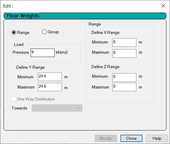
Total Floor Load = 8.75 kNmm2���2
Roof slab
Slab weight = 3.75kNmm2���2
Insulaions and Water Proofing = 0.5kNmm2���2
MEP Services = 0.5kNmm2���2
Miscellaneous = 0.5kNmm2���2
Total Roof Load = 5.25kNmm2���2
Live Load
Floor slab
Common Corridor = 3kNmm2���2
Total Floor Load = 3kNmm2���2
Roof slab
Accessible Roof = 1.5kNmm2���2
Total Roof Load = 1.5kNmm2���2
Design of Slab
Span Shorter Direction (Clear) ly = 3.125.00 m
Span Longer Direction (Clear) lx = 5.500 m
Live Load on the Slab LL= 3.00 kN / m2
Compressive stength of concrete fck = 40 N / mm2
Yield strength of steel fy = 415 N / mm2
Unit weight of concrete Ƴ = 25.00 kN / m3
Unit weight of floor finish 100 mm Ƴ= 22.00 kN / m3
Clear concrete cover =25.00 mm
Bearing of slab B=250.00mm
Step 1
Cl 24.1
Span to effective depth ratio l/d = 32
Minimum effective depth d = 97.66 mm
Overall depth D = 127.66 mm
Provide Overall depth D = 150.00 mm
Dia of bars for short direction Φ=10mm
Dia of bars for long direction Φ = 10 mm
Effective Depth d=120.00mm
Loading on the slab
Dead Load of the slab (DL) 3.75.00kN / m2
Super Dead Load = 5.00 kN / m2
Live Load on the slab=3.00 kN / m2
Total Load on the slab (TL) =12.00kN / m2
Design Load = (Total Load x Load Factor i.e. 1.5) ie 18.00 kN / m2
Effective Span lx = 5.17 m
ly=5.17 m
Ratio ly/lx= 1.000 Two Way
T26/27
1.0 ax 1.10 ay
For negative moments (at top) 0.047 0.047 0.053 0.047
For positive moments (at bottom) 0.035 0.035 0.045 0.035
Step 2
BM per unit width of slab Mx = ax w lx2 My = ay w lx2
For negative moments (at top) 22.60 22.60KN-m/m
For positive moments (at bottom) 16.83 16.83nKN-m/m
Shear force , V 0.5wlx 46.52kN/m
Step 3
To check the effective depth of slab
Mu,lim = 0.138fckbd2
d=63.99 mm
Step 4
Depth of slab for shear force
T20 τc,max =4N/mm2
τc=0.3
Cl 40.2.1 k=1.2D=200mm
τc=0.36 N/mm2
τv=Vu / bd
=0.28N/mm2
τv�� < τc < τc,max
0.28 0.36 4
SAFE
Step 5
Determination of areas of steel
Mu = 0.87fyAstd(1-Astfy/fckbd)
For Negative moments Mu Top = 22.60
Ast = 463.99 mm2/m
For Positive moments Mu Bot = 16.83
Ast = 345.52 mm2/m
Step 5.1
Determination of distribution steel
Astmin =0.12bd
202.8mm2
Step 5.2
Selection of reinforcing bars
Area of bars (Top steel) =113.04mm2
Spacing =244
=240mm
Provide 12mm bars at a spacing 240mm
Area of bars (Bottom steel=113.04mm2
Spacing =327
=300mm
Provide 12mm bars at a spacing 300mm
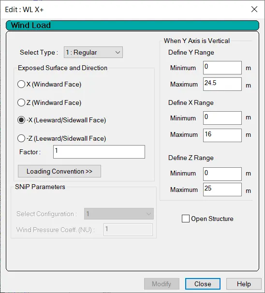
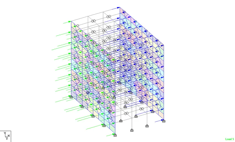
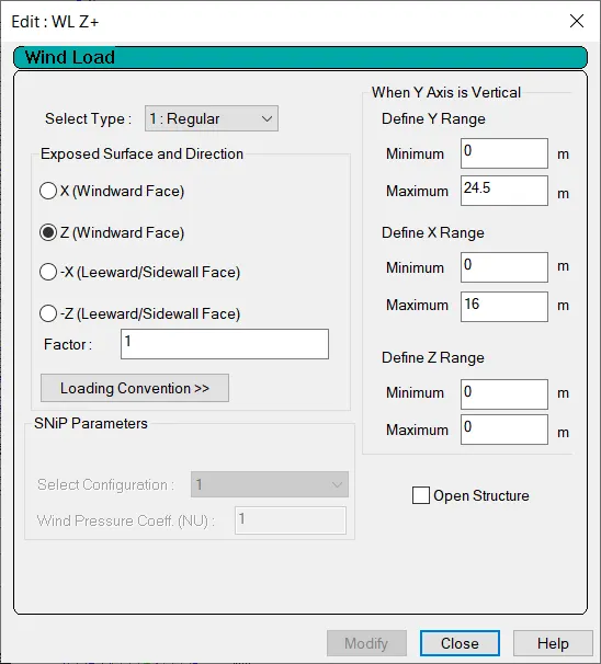
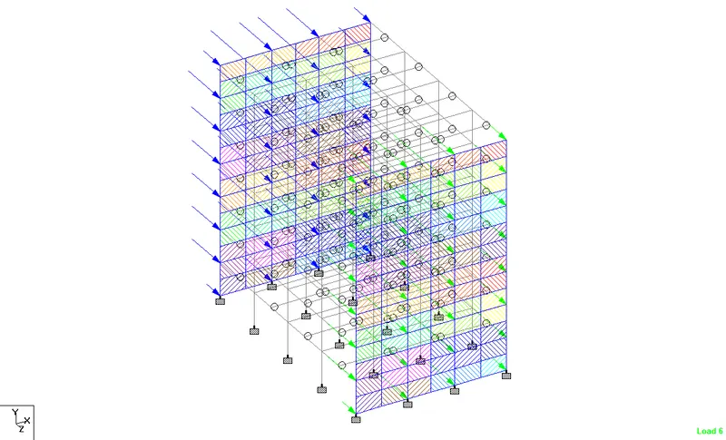
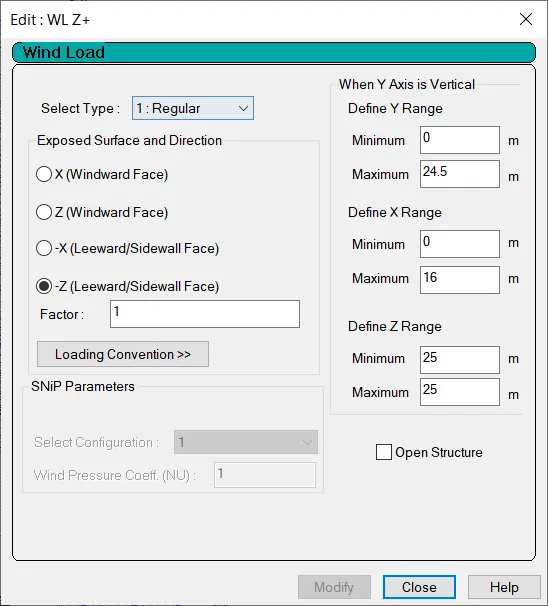
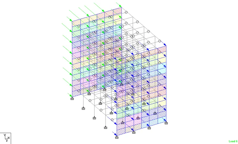
Calculation of wind load
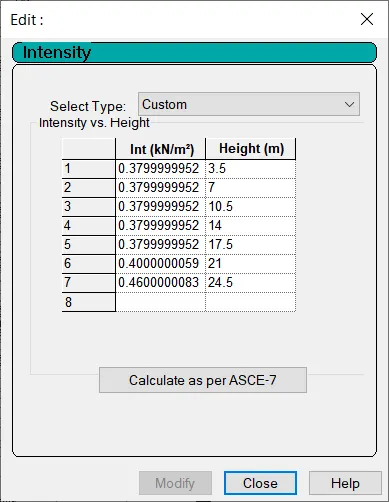
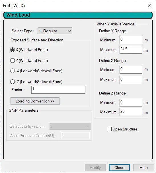
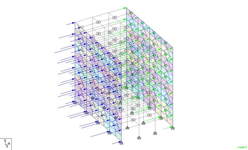
Design Wind Speed Vz =Vb k1 k2 k3 k4 m/s
Basic Wind Speed (Banglore) Vb =33 m/s
Probability factor k1 = 1
Terrain factor , Category for k2 =Category 4 B
Topography factor k3= 1
Design Wind Pressure Pz=0.6 Vz2
Height k2 Vz Pz Pz in kN
3.5 0.76 25 377.40 0.96
7.0 0.76 25 377.40 0.96
10.5 0.76 25 377.40 0.96
14.0 0.76 25 377.40 0.96
17.5 0.76 25 377.40 0.38
21.0 0.78 26 397.93 0.43
24.5 0.84 28 461.04 0.46
Calculation of seismic load:
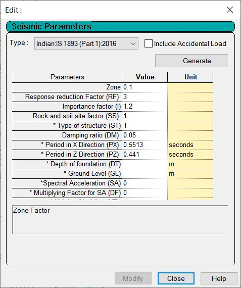
Design Base Shear VB = Ah W kN
Design Horizontal Acceleration Coefficient Ah = {(Z/2) x (Sa/g)}/(R/I)
Zone factor Z = 0.1 (Banglore)
Soil Condition factor , Sa / g
T=0.09h/√d
Height of building h=24.5m
Base dimension of building Along X = 16
Along Z = 25
T along X =0.5513s
T along Z =0.4410s
Sa / g =1.814 Along X
Sa / g =2.268 Along Z
Response Reduction Factor R = 3
Importance Factor I= 1.2
Horizontal Acceleration Coefficient Ah = 0.0363 Along X
Ah =3.68%
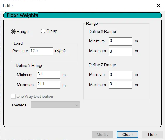
Seismic Weight
Area of Each floor A = 400m^2
Due to Dead Loads , Typical Floor DL = 12kN/m^2
W DL = 5000kN
Due to Dead Loads ,Roof DL roof =9kN/m^2
=3600kN
Due to Live Loads , Typical Floor LL = 3kN/m^2
W LL = 300kN
Due to Live Loads , Roof LL = 1.5kN/m^2
W LL =0
Total Seismic Weight W = 35400kN
Design Base Shear VB = 1284.35kN
Horizontal acceleration cofficient Ah= 0.0454 Along Z
=4.54%
Seismic Weight
Area of Each floor A = 400m^2
Due to Dead Loads , Typical Floor DL = 12.5 kN/m^2
W DL = 5000kN
Due to Dead Loads ,Roof DL roof =9kN/m^2
=3600kN
Due to Live Loads , Typical Floor LL = 3kN/m^2
W LL = 300kN
Due to Live Loads , Roof LL = 1.5kN/m^2
W LL =0
Total Seismic Weight W = 35400kN
Design Base Shear VB = 1605.35kN
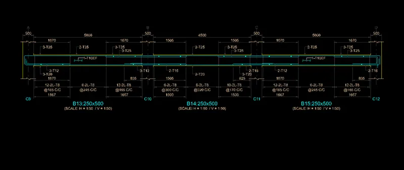
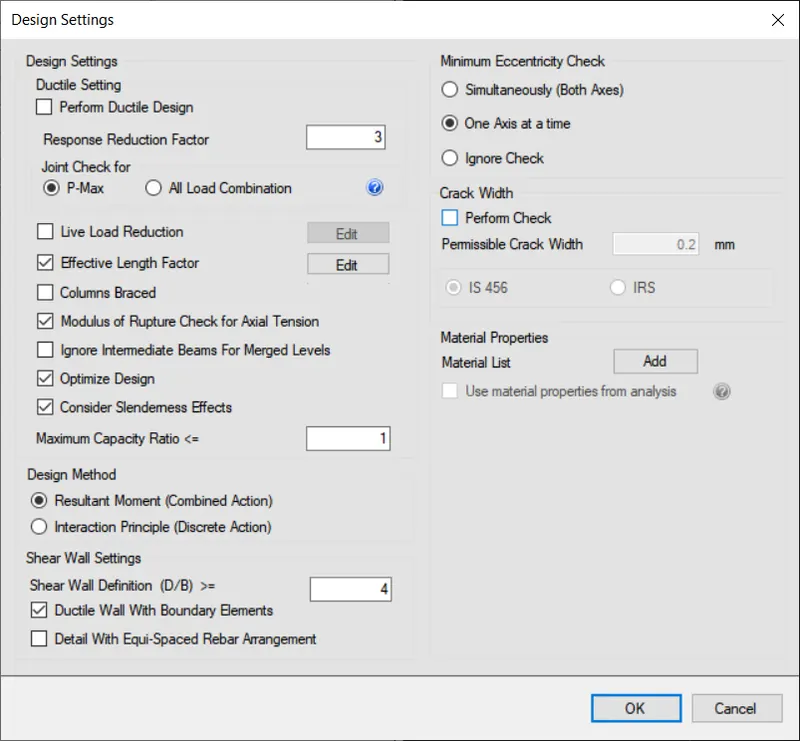
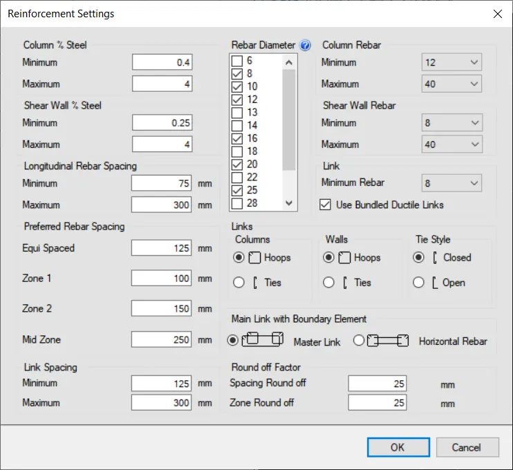
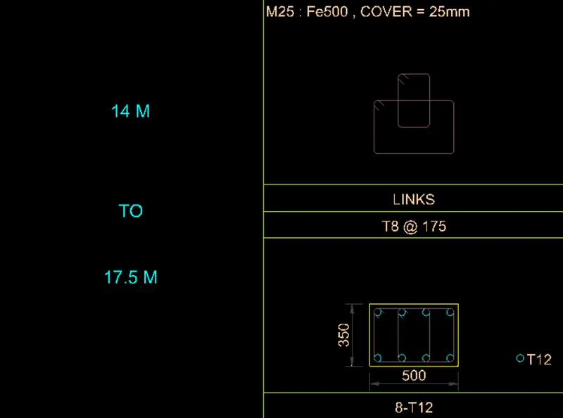
The Design-Builder shall create and maintain a comprehensive Basis of Design Report (BODR) for the Project. The purpose of the Pre-Design Investigation (PDI) is to identify and address data gaps by conducting field investigations to develop the Basis of Design Report and RD Work Plan.
-
The purpose of the Pre-Design Investigation (PDI) is to identify and address data gaps by conducting field investigations to develop the Basis of Design Report and RD Work Plan.
-
The Design-Builder shall submit the Basis of Design Report Record Document for Review and Comment upon completion of all elements of the BODR.
-
In the event that Developer proposes to use any software other than that 4 listed and as part of the Basis of Design Report in accordance with Section GP 110.01.2.2 of 5 the TPs, Developer shall submit proposed Geotechnical Software (including input and output 6 files for verification data) to ADOT for approval.
-
Identify applicable design criteria (the Design Criteria as defined by Section 5.10.1 can be included here as part of the Basis of Design Report), considerations, influences, and factors.
-
The Design-Builder shall submit the comprehensive Basis of Design Report Record Document for Review and Comment upon completion of all elements of the BODR.
-
The first submittal related to a Design Unit shall include, or be preceded by, a Basis of Design Report (BODR). The Basis of Design (BOD) is a very important document for every project. The basis of design or project design basis provides all the principles, business expectations, criteria, considerations, rationale, special requirements, and assumptions used for decisions and calculations required during the design stage. So, a basis of design is a project baseline and overview to kickstart the project activities. The Basis of Design document describes the technical approach planned for the project. Preliminary project technical details are incorporated in this essential document. The BOD is prepared during the pre-design stage and it serves as the basis for all the design calculations and other design decisions. Note that, BOD is not a substitute for code and standard guidelines or project design drawings. But a BOD simply includes the list of individual items to support the design work process based on the owner’s project requirements. Even though the basis of design starts at the pre-design phase, the document is dynamic in nature. As the design work progresses, the basis of the design document is updated to include a specific description of the system and components, its function, how it relates to other systems, sequences of operation, and operating control parameters. However, BOD does not include detailed project information or calculations.
- It documents the major process and assumptions behind specific decisions.
- A BOD concisely captures the owner’s requirements and vision into technical terms and design parameters.
- For the commissioning team, BOD is a very important document to evaluate the ability of a design.
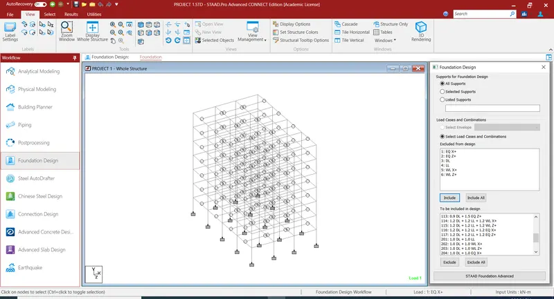
- Firstly, choose the “New” option on the welcome page of STAAD.Pro CONNECT Edition Update 5 to create a new model.
- Secondly, under the “Model information” tab we will have to add the existing file location which will be used as the seed file.
- Next, we will have to add all the other model information along with the seed file location as mentioned above.
- Finally, on the creation of the new model, all the information of the seed file will be present in the new model.
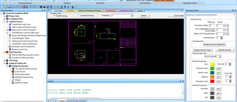
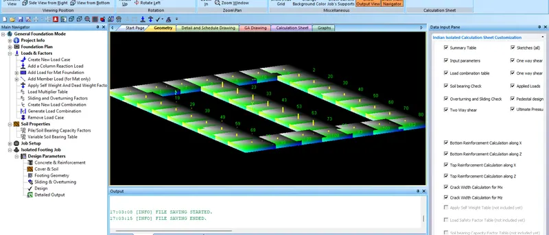
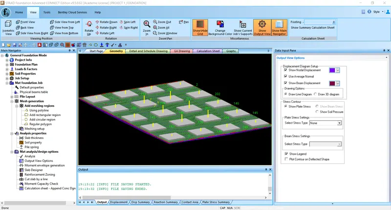
STAAD Foundation Advanced is a comprehensive structural foundation design and analysis software that includes specialized features for foundations of many types. You can perform isolated, combined, pile cap and mat foundations or more complex foundations including horizontal vessel foundations, tank annular ringwall, lateral analysis of pile/drilled piers, and vibrational analysis for machine foundations.
Design a wide variety of foundations, from simple spread footings to complicated mats and specialized machinery pads, with the extensive support of international standards.
Apply wind and seismic loads using built-in load generators. Calculate loading parameters automatically. Combine lateral load cases with gravity and other types of loads using load combination generators. Analyze machine block foundation for dynamic loading. Leverage wizard-based input for fast FEA solids model creation, various loading, and soil spring options.Center lines are used:
- to represent symmetry,
- to represent paths of motion,
- to mark the centers of circles and the axes of symmetrical parts, such as cylinders and bolts.
Break lines are used to show where an object is broken to save drawing space or reveal interior features.
Break lines come in two forms:
- a freehand thick line, and
- a long, ruled thin line with zigzags.
Dimension and extension lines are used to indicate the sizes of features on a drawing.
Section lines (hatching) are used in section views to represent surfaces of an object cut by a cutting plane.
Phantom lines are used to represent a movable feature in its different positions.
Stitch lines - to indicate a sewing or stitching process.
The National Building Code of India (NBC), a comprehensive building Code, is a national instrument providing guidelines
for regulating the building construction activities across the country. It serves as a Model Code for adoption by all
agencies involved in building construction works be they Public Works Departments, other government construction departments,
local bodies or private construction agencies. The Code mainly contains administrative regulations, development control rules
and general building requirements; fire safety requirements; stipulations regarding materials, structural design and
construction (including safety); building and plumbing services; approach to sustainability; and asset and facility management.The Code was first published in 1970 at the instance of Planning Commission and then first revised in 1983.
2)Overviews of gantry cranes pdf, including types of gantry crane designs pdf, and types of gantry crane spcifications pdf for you to download to select the right type of gantry crane for your application. More information, please feel free to contact us. WhatsApp/ WeChat: + 86 151 3871 1597.
Overview of gantry crane
- Gantry crane concept- The structure of gantry crane is similar to a door frame, with legs under the main beam to support it, and it travels on rail with wheels on the ground. Cantilever is he extension of gantry span which enables the hoisting trolley runs beyond the legs of the beam.
- Application of gantry cranes- Storage, station, port, and other outdoor yards are examples of Gantry crane applications.
- Gantry crane loading capacity- Rated capacity from 1 to 900 tons
- Advantages of gantry cranes: high space utilization, vast range of operation, wide adaption, strong commonality, and are frequently employed in port yards.
- Gantry crane structure: Gantry cranes have its own legs and wheels, move on rails, and the rails are fixed to the ground.
Main crane specifications of standard gantry cranes
The main overhead crane specifications andparameters of the general use gantry cranes in terms of crane capacity, span, crane services duty and crane applications are presented for your reference. As for the process crane, please feel free to contact us directly to get your customized gantry cranes.
Main crane specifications and parameters of general use gantry cranes :
- Lifting capacity of gantry cranes : 5 ton-550 ton.
- Span of electric gantry cranes:3 to 35m,
- Lifting height of electric gantry cranes:Customized according to your applications,
- Working duty of electric gantry cranes: (A3, A4, A5, A6).
- Working ambient -25℃~+40℃, moisture ≤85%, altitude below 1000 meters,
- Power supply: 380V, 50Hz, 3phases, (Adjustable according to customer's different requirement).
Main types of gantry cranes
Gantry cranes can be grouped into various types based on different terms, can provide a complete range of gantry cranes, i.e. full gantry cranes, semi-gantry cranes and portable gantry cranes, including, single girder, double girder, single leg, double leg, and cantilever styles for indoor or outdoor service. The capacities, spans, heights can be customized. The main types of gantry cranes are presented for your reference.
- Single girder gantry crane - Single girder gantry crane is usually adopted box shaped gantry girder design with the features of simple structure easy manufacturing and installation, and light self-weight. Compared with double-girder gantry cranes, the overall stiffness of single girder gantry crane is weaker and usually used when the loads Q≤50 ton and the span S≤35m.
- Double girder gantry crane Double girder gantry cranes is the most frequently used structure design, with the features of strong bearing capacity, large span, good overall stability, and coming in many varieties, but the self-weight of the double girder gantry crane is larger and their processing cost is higher compared with single-girder gantry cranes .
- According to gantry girder design, double girder gantry cranes can be grouped into - box shaped girder design gantry crane and truss girder design gantry crane . At present, box-shaped girder design gantry crane is more frequently used.
- Box girder gantry crane -The box shaped gantry girder is welded with steel plates , with features of high safety, stiffness and other, etc. Box gantry girder design is usually used for gantry cranes with large and super large tonnages.The box gantry girder design also has the drawbacks of high production cost, heavy self weight and poor wind resistance.
- Truss gantry crane -The truss gantry girder is welded with angle steel or I-beam, featured as low manufacturing cost, light self-weight, and good wind resistance. However, due to the large amount of welding points and the inborn defects of the trusses structure, the truss gantry girder has the disadvantages of large deflection, low rigidity, low reliability, and frequent welding spots detection. Truss cranes are suitable for application with low requirements on safety and lifting capacity.