Project 1_Analyze and design a steel building to 10T CRANE as per IS standard code using TEKLA STRUCTURAL DESIGNER.
Aim :-
To analyse and design a steel building to 10T CRANE as per IS standard code in TEKLA STRUCTURAL DESIGNER.
Procedure:
- Open the TEKLA software and select structure window.
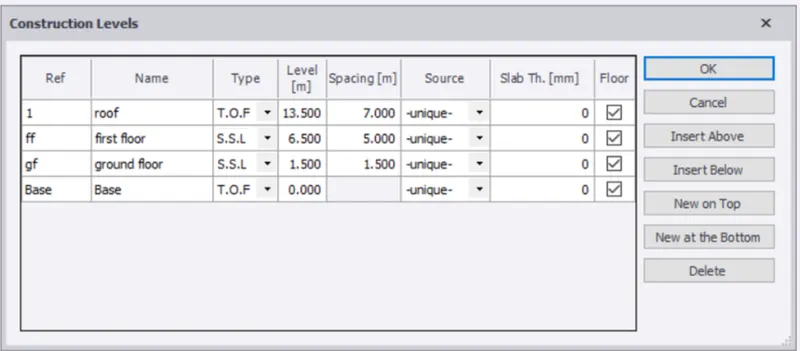
- Now enter the levels as base, ground floor, first floor and roof as per the question
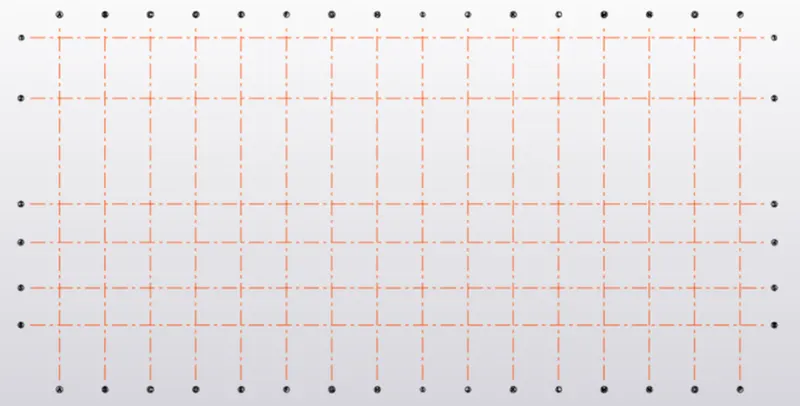
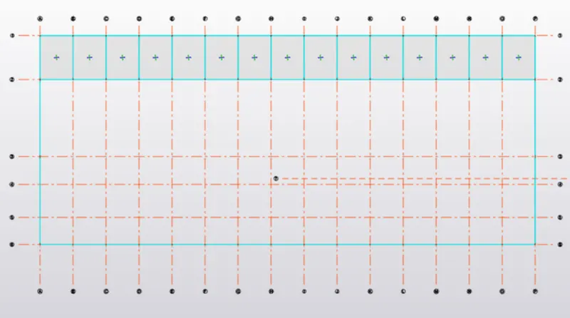
- Now select the grid lines and draw them according to the ground floor plan
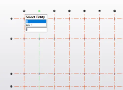
- Now from the Manage property sets, define a new concrete column as 400*800 with grade of M45 and place the columns on the grid intersections
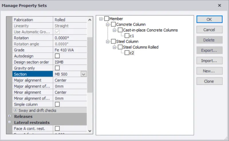
- Now define a steel column of section ISMB 500, and place it at the grid intersections of first floor.
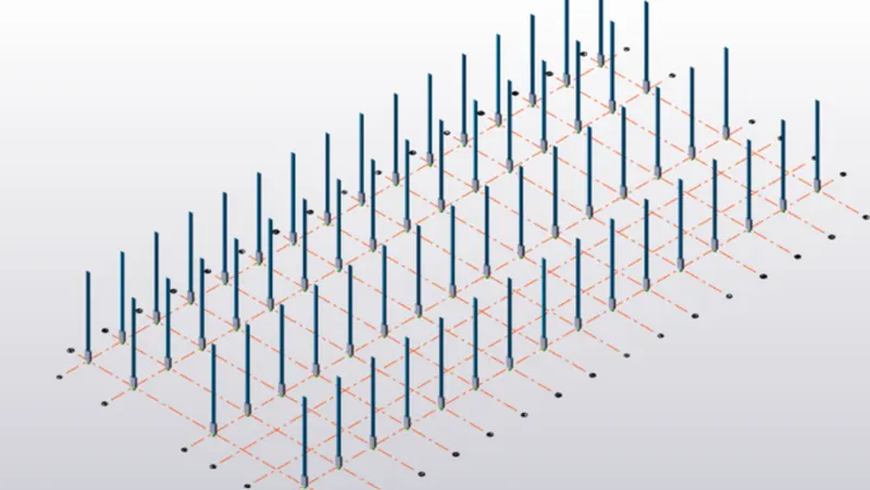
- Now define the primary beams as ISMB 500 and place it on the ground floor
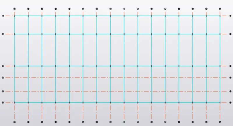
- Similarily draw the same beams on the first floor and roof.
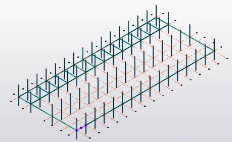
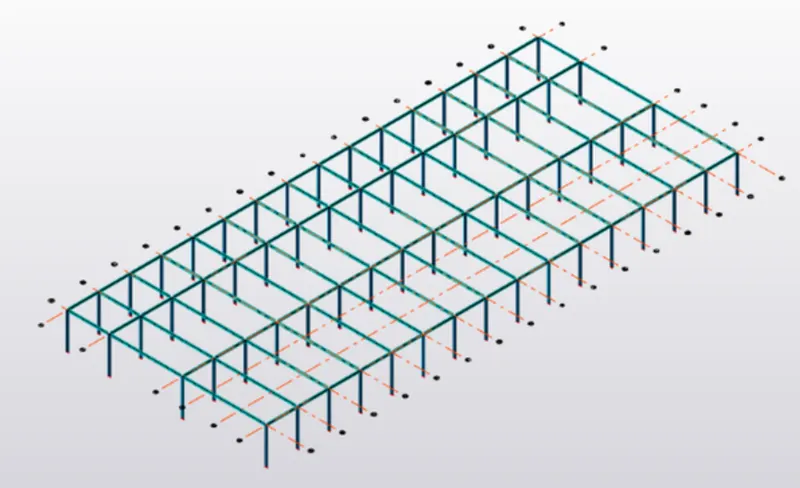
- Now define the frames for the model and select any one frame and draw a central vertical line. Slope of the roof is 18 degree, so the height at which the rafter has to be placed should be determined. tan 18 = ht./19 => ht. = 6m
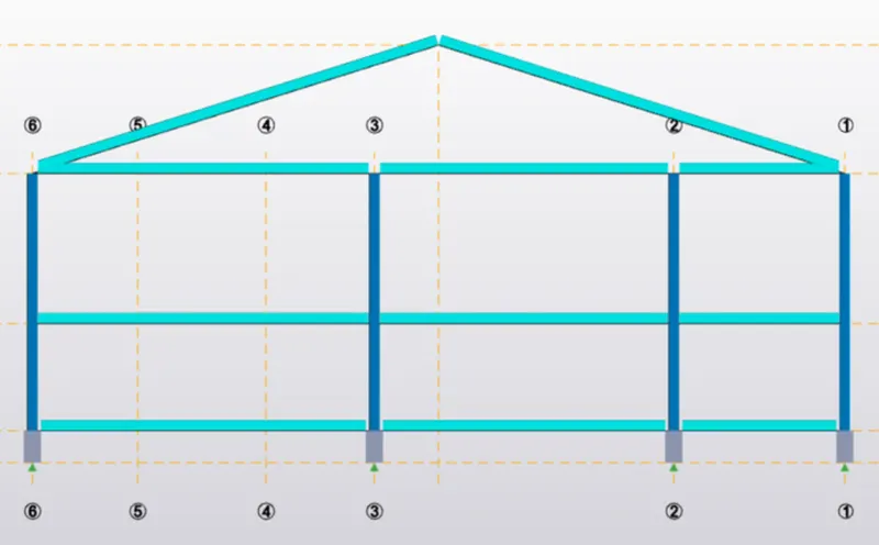
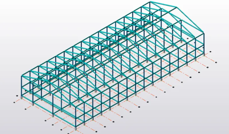
- Now we have to go to the slab sections and define a slab of thickness of 300mm and grade M50. Since the first layer is a square shape, it has to be a two way slab and the other two rows are one way.
- The same process is repeated for all the three floors
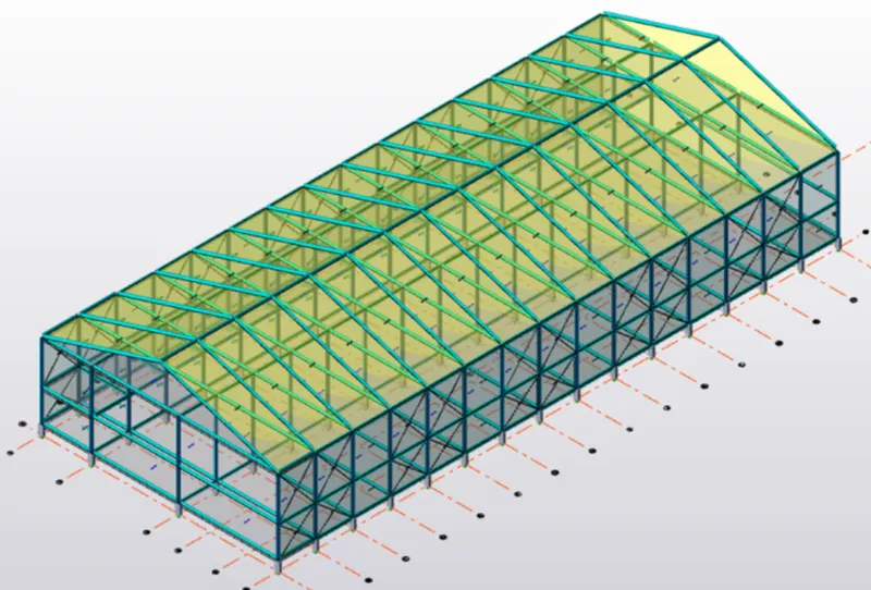
- Now we have to assign the roof panels and wall panels
Calculation of Dead load:
- Finish of 50 mm = 0.5*25 = 1.2KN/m
- Brickwall load for ground floor = 0.15*20*5 =15.5KN/m
- Brickwall load for first floor, second floor and roof = 0.15*20*7 = 21.2KN/m
- Now apply all these loads to the entire model
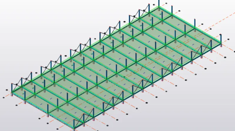
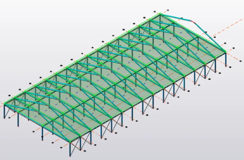
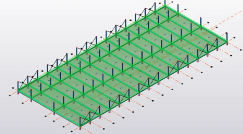
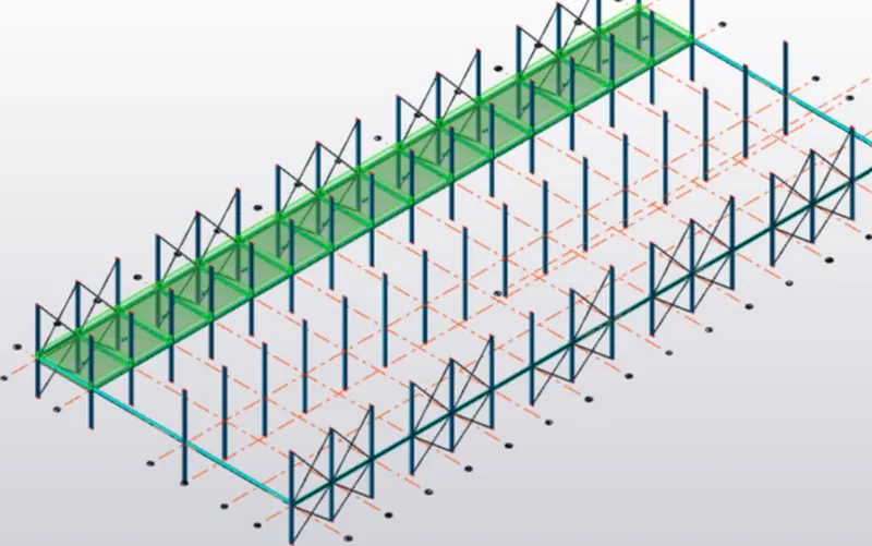
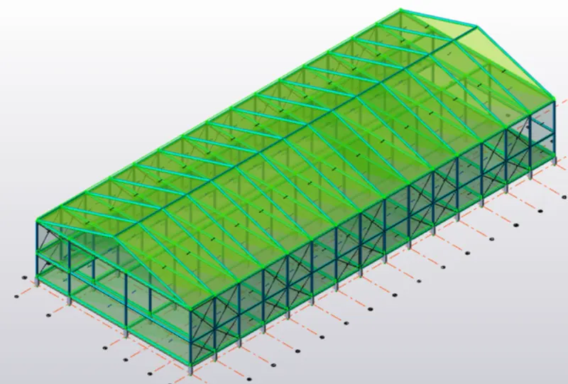
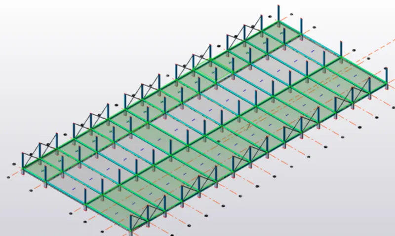
Calculation of Live Load:
- Meeting room = 2KN/m
- Toilet = 2KN/m
- Office Room = 2.5 KN/m
- Maintenance room = 2.5KN/m
- Pantry =5KN/m
- Staircase = 5KN/m
- Now we have to apply all these loadsto each floor of the model
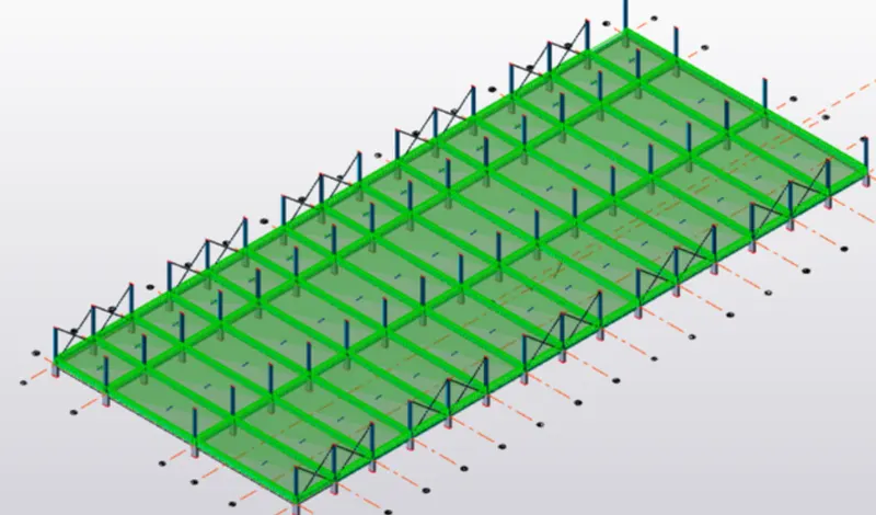
Calculation of Wind Loads:
- Vz= Vb*k1*k2*k3*k4
Vb = 39 m/s
From Table 1, IS 875-3 , k1 = 1
From Table 2, IS 875-3, k2 = 1.03
k3 = 1 ; k4 =1
Vz = 39&1*1.03*1*1 = 40.17 m/s
- Pz = 0.6*Vz^2
Pz = 0.6*40.17^2 = 0.968 KN/m^2
- Along face A
Interior
- H= 18m
- L= 90m
- w= 38m
- Cpe =0.7
- Cpi =0.5
- Cp= 0.2
- Pz = 0.968KN/m^2
- Load = 0.1936 KN/m
Exterior
- H= 18m
- L= 90m
- w= 38m
- Cpe =0.7
- Cpi =-0.5
- Cp= 1.2
- Pz = 0.968KN/m^2
- Load = 1.16 KN/m
- Along face B
Interior
- H= 18m
- L= 90m
- w= 38m
- Cpe =-0.25
- Cpi =0.5
- Cp= -0.75
- Pz = 0.968KN/m^2
- Load = -0.726 KN/m
Exterior
- H= 18m
- L= 90m
- w= 38m
- Cpe =-0.25
- Cpi =-0.5
- Cp= 0.25
- Pz = 0.968KN/m^2
- Load = 0.242 KN/m
- Along face C
Interior
- H= 18m
- L= 90m
- w= 38m
- Cpe =-0.6
- Cpi =0.7
- Cp= -1.3
- Pz = 0.968KN/m^2
- Load = -1.25 KN/m
Exterior
- H= 18m
- L= 90m
- w= 38m
- Cpe =-0.6
- Cpi =-0.7
- Cp= 0.1
- Pz = 0.968KN/m^2
- Load = 0.0968 KN/m
- Along face D
Interior
- H= 18m
- L= 90m
- w= 38m
- Cpe =-0.6
- Cpi =0.1
- Cp= -0.7
- Pz = 0.968KN/m^2
- Load = -0.6776 KN/m
Exterior
- H= 18m
- L= 90m
- w= 38m
- Cpe =-0.6
- Cpi =-0.1
- Cp= -0.5
- Pz = 0.968KN/m^2
- Load = -0.484 KN/m
- Loads to roof considering one part as EF (Slope = 18 degree)
Interior
- H= 12m
- L= 90m
- w= 38m
- Cpe =-0.4
- Cpi =0.7
- Cp= -1.1
- Pz = 0.968KN/m^2
- Load = -1.06 KN/m
Exterior
- H= 12m
- L= 90m
- w= 38m
- Cpe =-0.4
- Cpi =-0.7
- Cp= 0.3
- Pz = 0.968KN/m^2
- Load =0.2904 KN/m
- Now we have to apply the loads along each face of the model
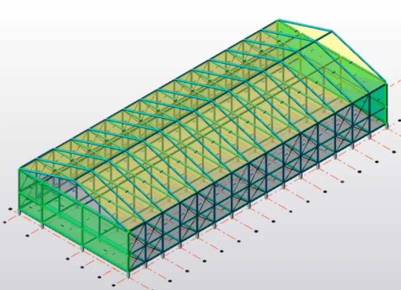
Calculation of Crane load:
- Weight of crab = 35KN
- Weight of crane = 160KN
- Crane capacity = 100KN
- Wheel base =3m
- Distance between gantry rails = 20m
- Distance between gantry column = 6m
- Max wheel load = Max point load + Weight of crab =135KN
- Self weight of crane = 160KN/20 = 8KN
- Taking moment about A,
Rb*20-135*1-8*20*10 =0
Therefore Rb= 86.75KN
- Taking moment about B,
Ra*20-135*19-8*20*10=0
Therefore Ra= 208.25 KN
- Max load on each wheel =Ra/2 = 104.13 KN
- Assume self weight of gantry girder =1.5KN/m
- Total dead load =1.8KN/m
- Taking moment about C,
Rd*6-104.13(0.75+3)-104.13*0.75=0
Therfore, Rd = 78.9 KN
- Taking moment about D,
Rc*6-104.13(2.25+3)-104.13*2.25=0
Therefore, Rc=130.15KN
Now, Rc+Rd = 208.25 KN
- Bending moment under wheel load due to live load = 78.9*2 = 156.18KNm
- Bending moment due to impact = 0.10*156.18 = 15.618 KN
- Total bending moment due to live load and impact load = 171.79KNm
- Bending moment due to dead load =WL/2 = 8.1 KN/m
- Max bending moment = 171.79 + 8.1 = 179.89 KNm
- Max shear force at D , Rc*16-104.13*6-104.13*3=0 . Therefore Rc= 156.18 KN
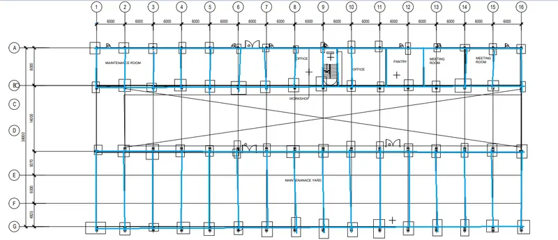
- First we will have to draft a rough postion of beams and columns in the plan using paint tool
Ground floor :
First floor :
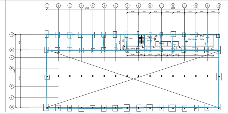
- The rough beam and column position are created for ground floor and first floor .
- after this new tekla file is opened and save it as project 1 .
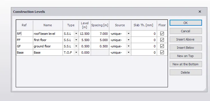
- New > Model > construction levels .
- Construction levels
- Base level > ground floor > 0.5 m
- Ground level > first floor > 5m
- first floor > roof beam level > 7m
- After this we have to go to the base level
- Add the grids
- First we add the vertical grids according to the dimensions
- select grid lines , pick the first point > grid 1
- Then select quick parallel >grid 2 > 6m .
- 12m > grid 3 > 18m >grid 4 > 24m > grid 5 and soo on till grid 16
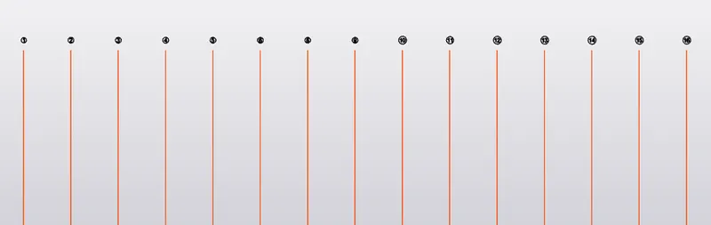
- Now select perpendicular grid line and name the grid as A
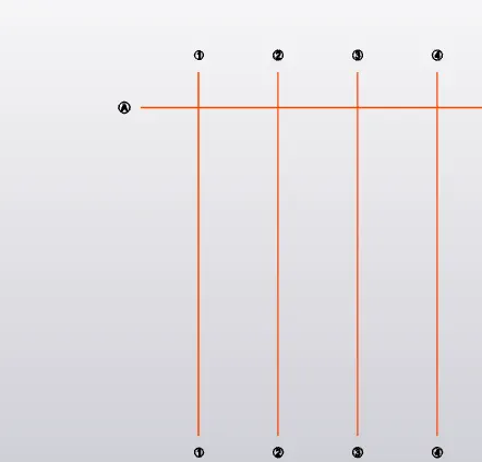
- After this parallel quick is selected and grid B is drawn with distance 8m
- 14m > grid C , 5.070 m >grid D , 4.925 m > grid E

- After this in the base level rc columns are created till ground floor Level
- Manage property sets > Concrete column > 400 x 800 section > M45
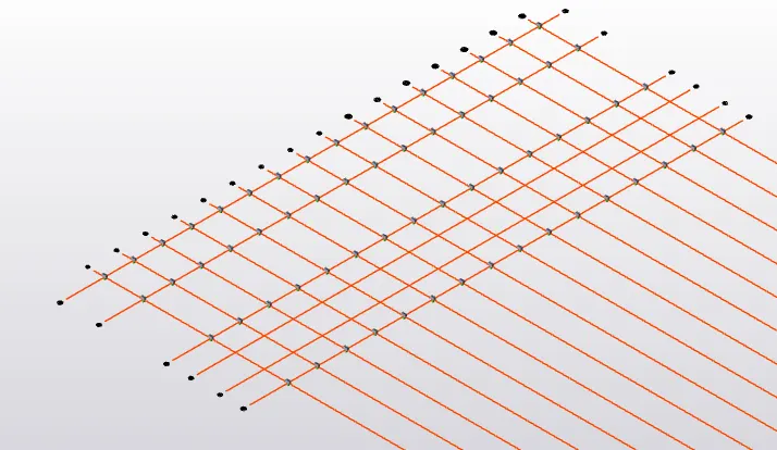
- Then steel column is added
- Manage property sets > steel column > ground floor to roof beam level
- ISMB> Universal columns > section > 365 X406 X393
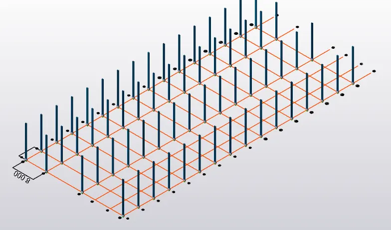
- After this primary and secondry steel beams are added
- In ground floor , first floor and roof floor
- Manage property sets > steel beam >uk > universal beams >1016X305x437
Ground floor :
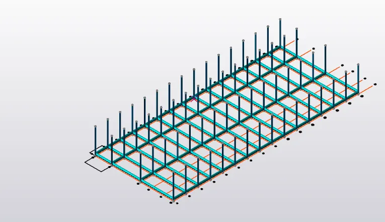
First floor :
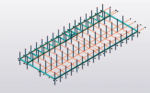
roof beam level:
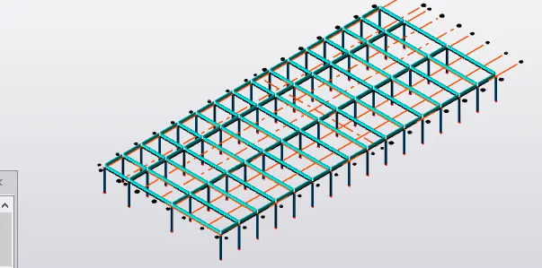
- Click on frame option and select grid 1
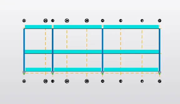
- draw grid lines at each end of distance 1328 mm with the help of construction line
- and draw the mid point the help of the construction line
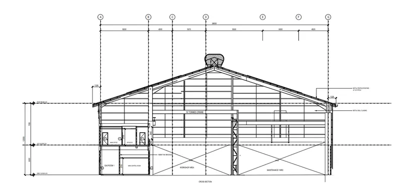
- as we known the slope is 18 degree
- horizontal distance is 18 m , therefore vertical distance is 6 m