Project 2_Analyze and Design the RC office building as per IS standard code in TEKLA STRUCTURAL DESIGNER
AIM : To develop a model as per the given plan and analyze and design the structure.
TOOLS USED :
- Paint.
- Manage property sets.
- Construction levels.
- Grids.
- Columns.
- Beams.
- REports.
- Model report.
- Show report.
- Interactive design.
- Slabs on beams.
- Frames.
- Roof panels.
- Wall panels.
- Loads.
- Loadcases.
- Seismic wizard.
PROCEDURE :
- Take the screenshots of the plan and open them in paint.
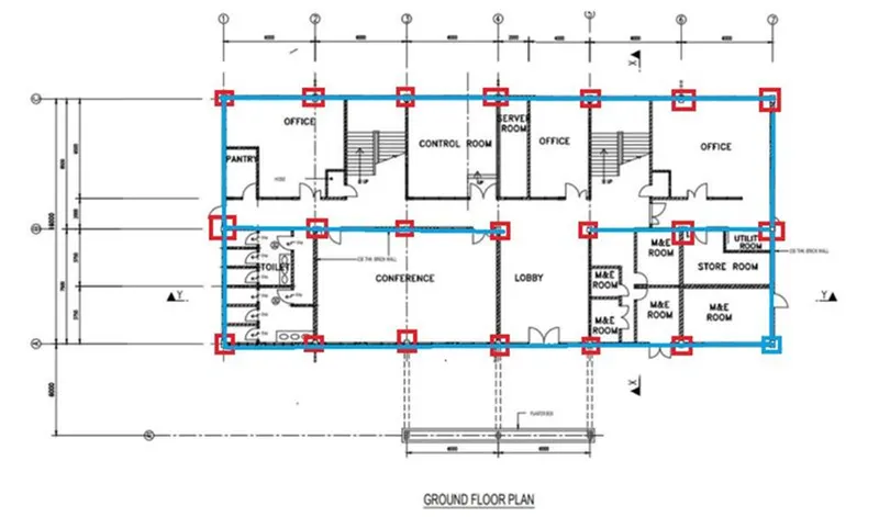
- Draw the positions of columns and beams in paint.
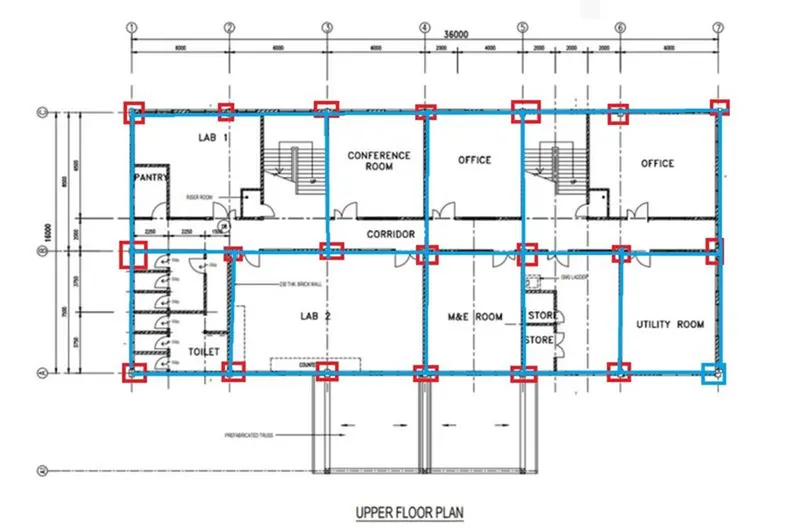
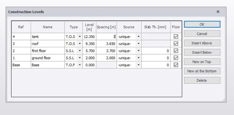
- Open tekla file and create the construction levels for the structure according to the plan.
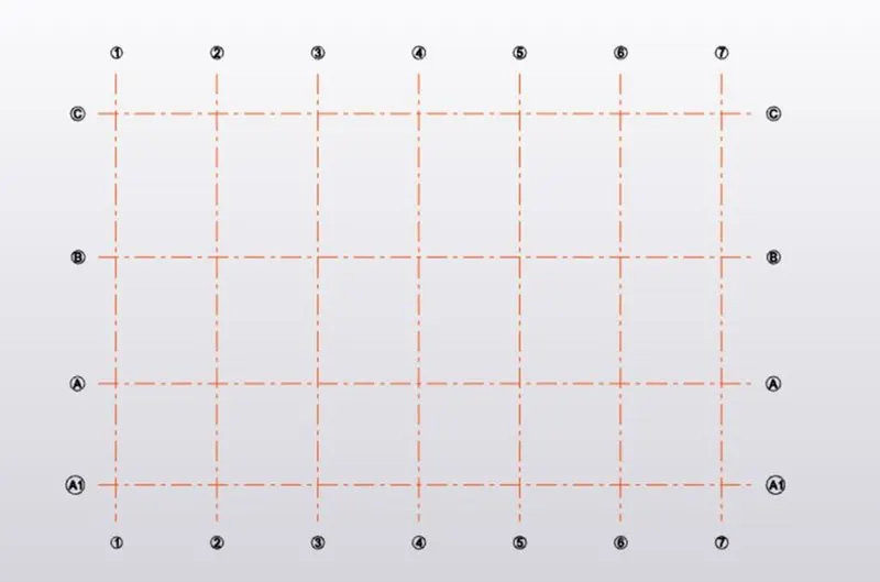
- Construct horizontal and vertical grid lines.
- Select the size of the concrete column section used in the construction as per the requirement.
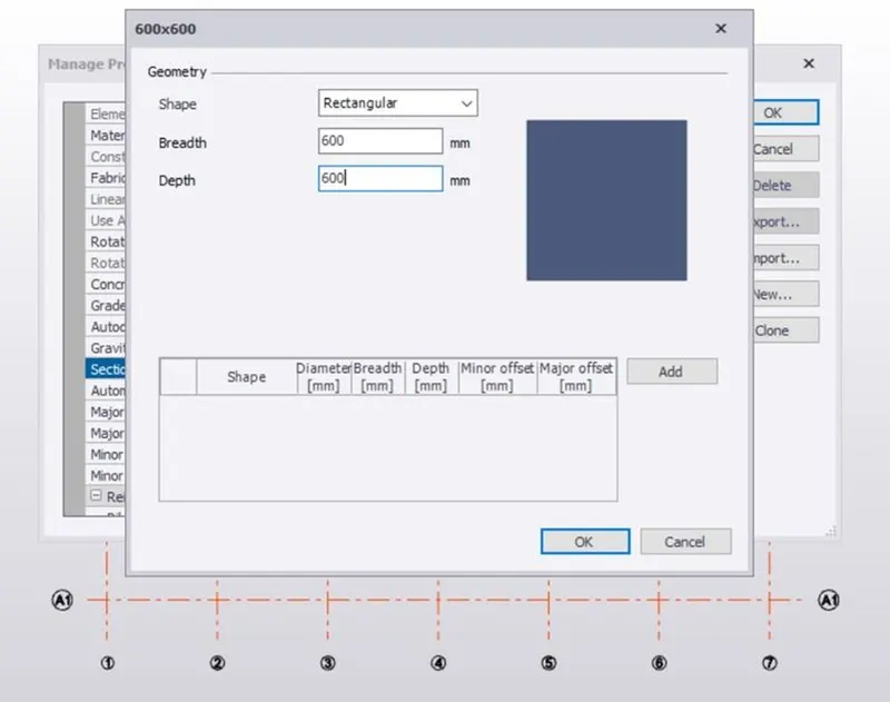
- Go to manage property sets and create members used for the modeling.
- Go to model tab and insert concrete columns in the structure.
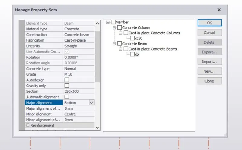
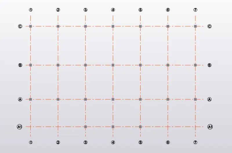
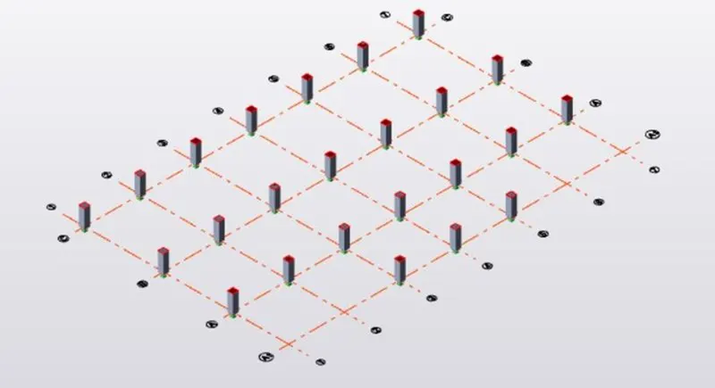
- Go to model tab and select the beams tool and draw the beams as per the plan.
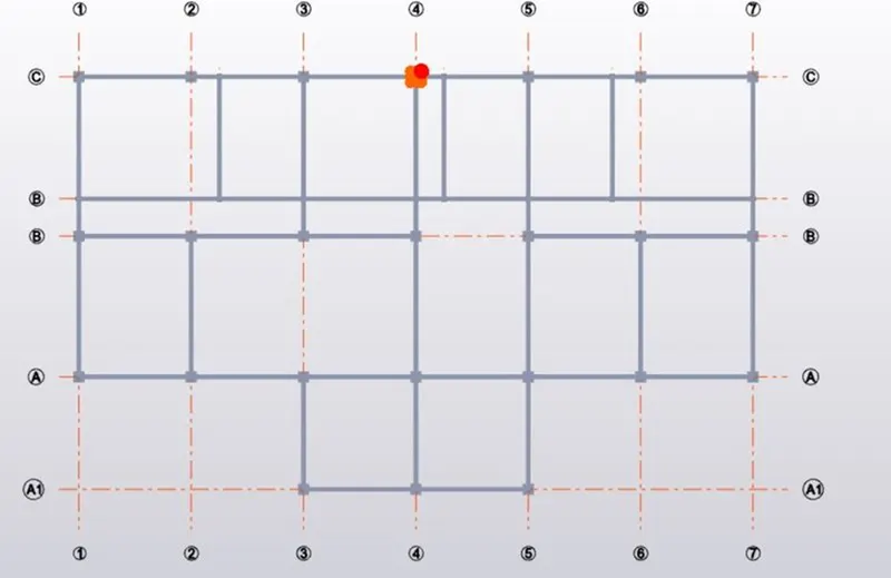
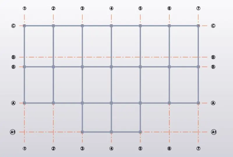
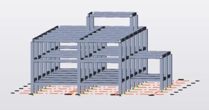
- We can check the structure in 3D for neat view.
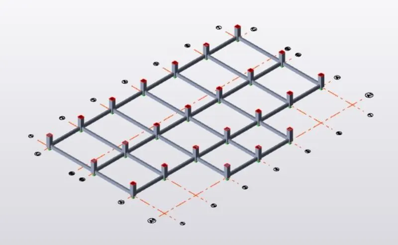
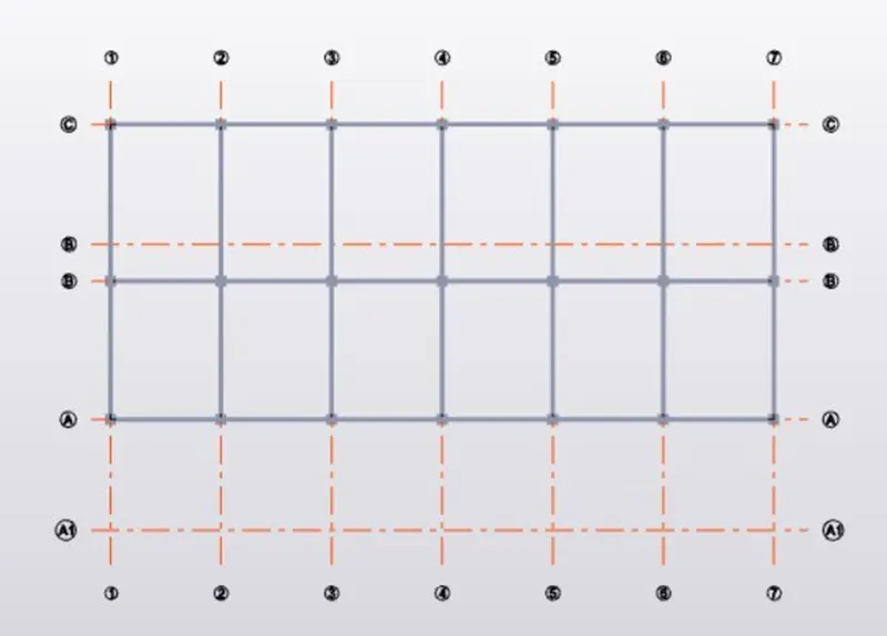
- Repeat the same process for the the levels as per the plan.
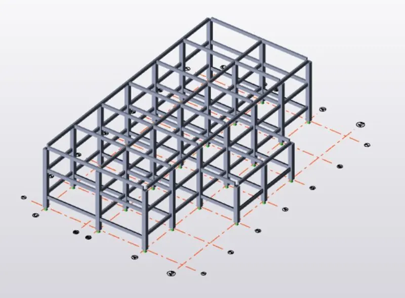
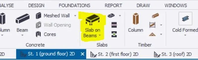
- Select slabs on beams and insert slabs for all the floors, where ever required.
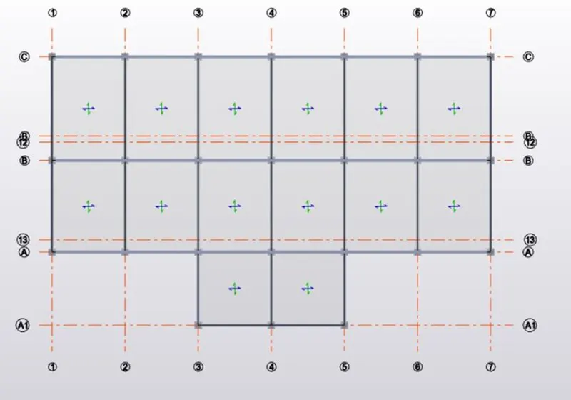
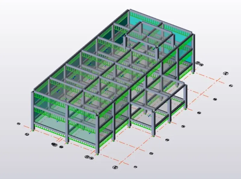
- Go to 3D view to get a clear view of the slabs inserted.
- Insert frams which will be helpful while applying loads on the structure.
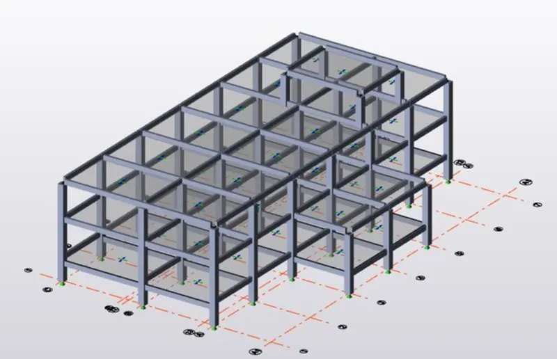
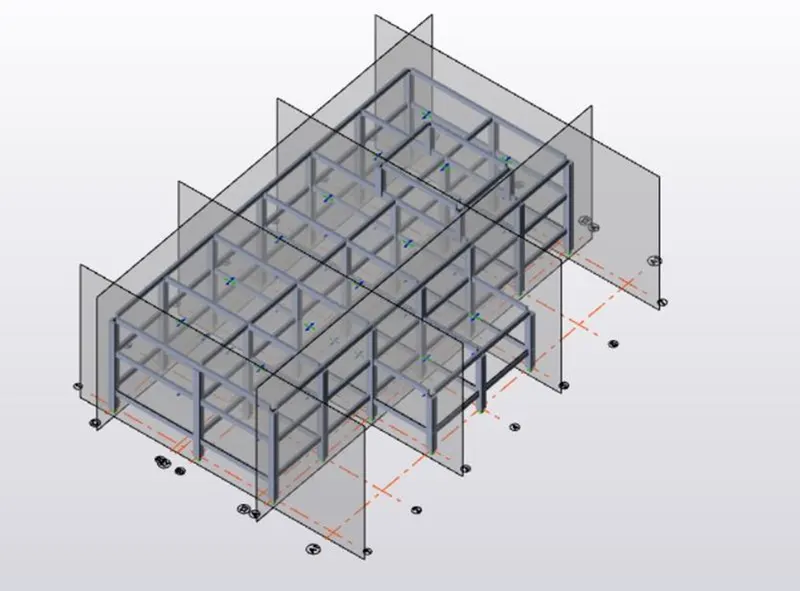
- Add wall panels to the structure.
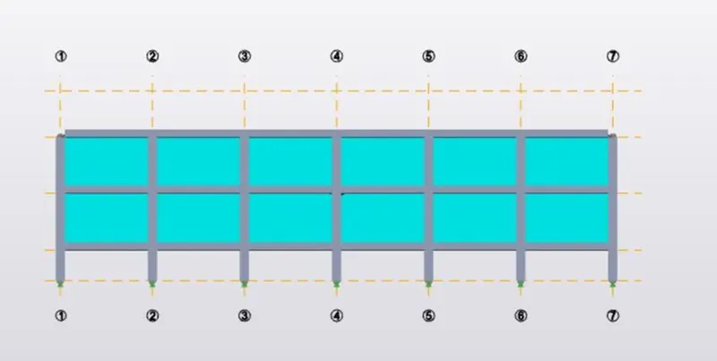
- Repeat the same step for all the walls.
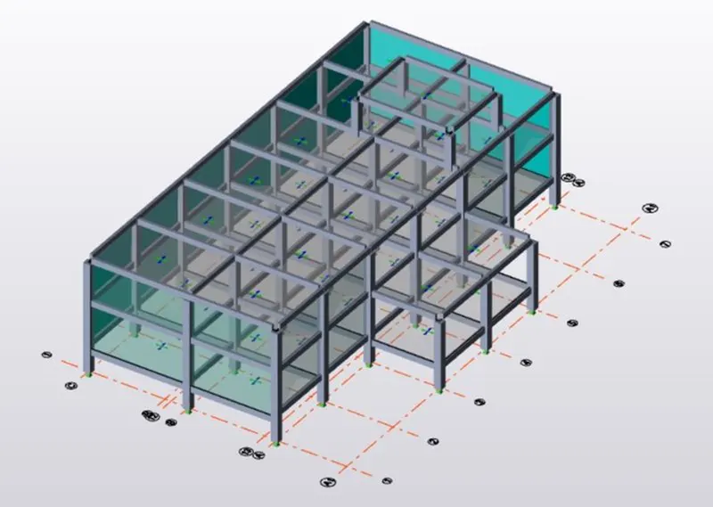
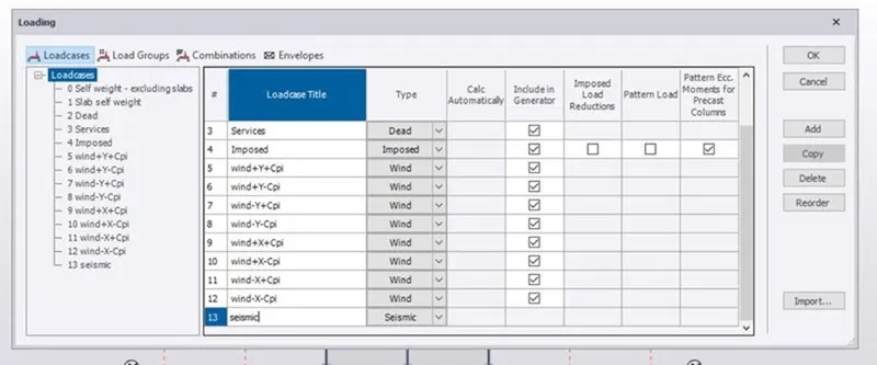
- Go to loads and create new load cases.
- Add the dead load on the beams.
- Add the dead loads on the slabs.
- Repeat the same step for all the floors.
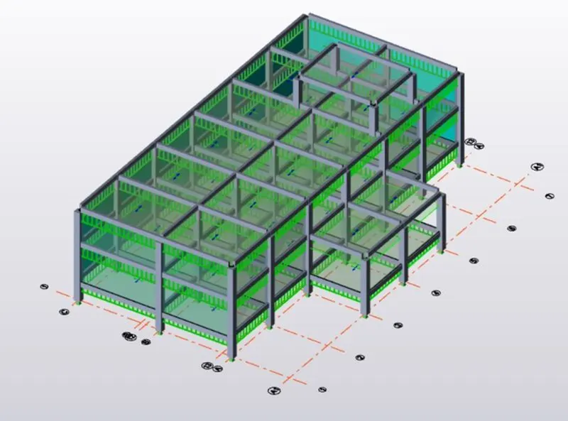
- Add live load on the structure for all the floors.
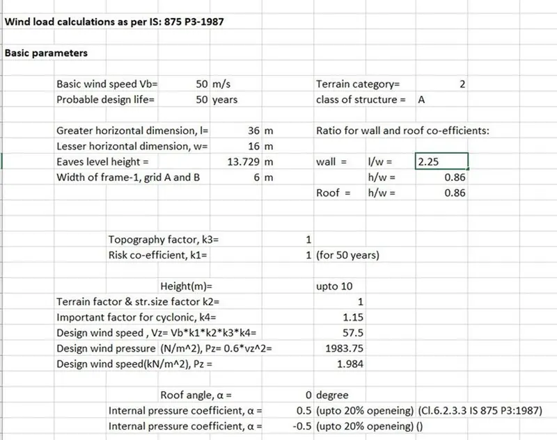
- Do the wind load calculation for all the sides for both X and Y ( including both +Cpi and -Cpi values).
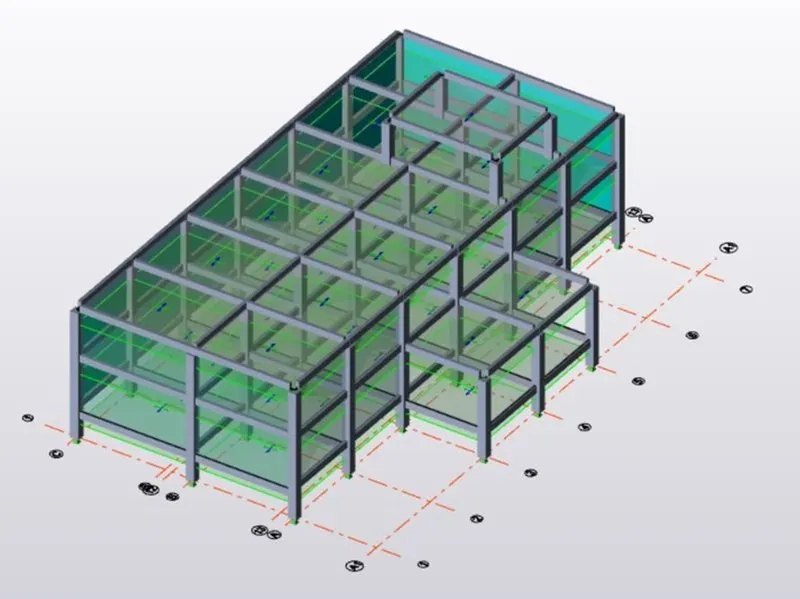
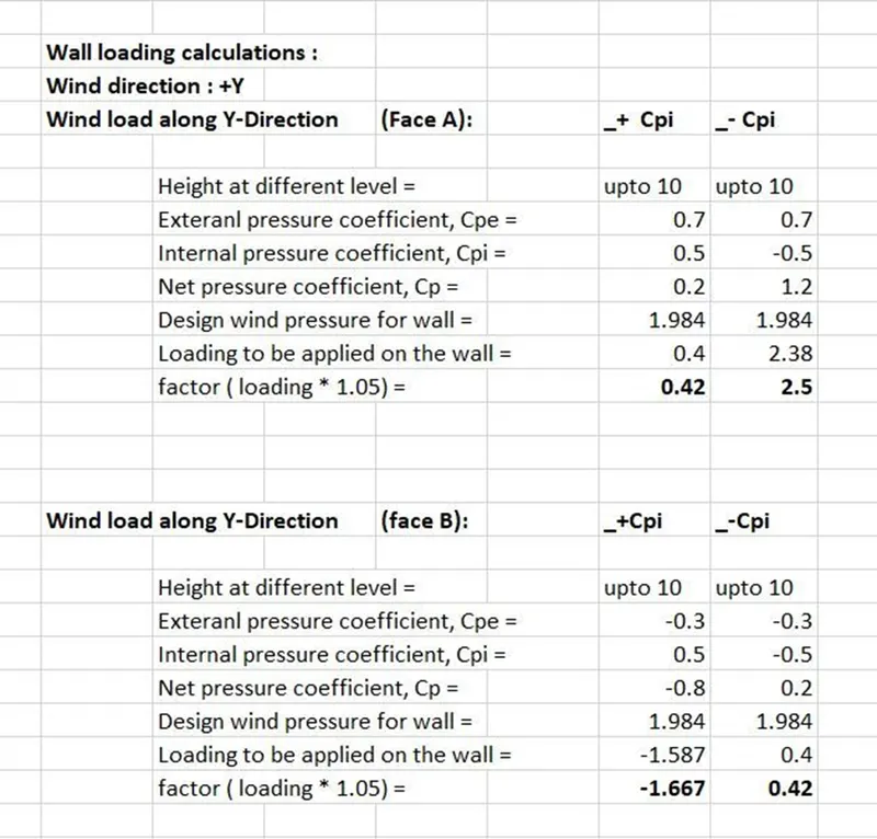
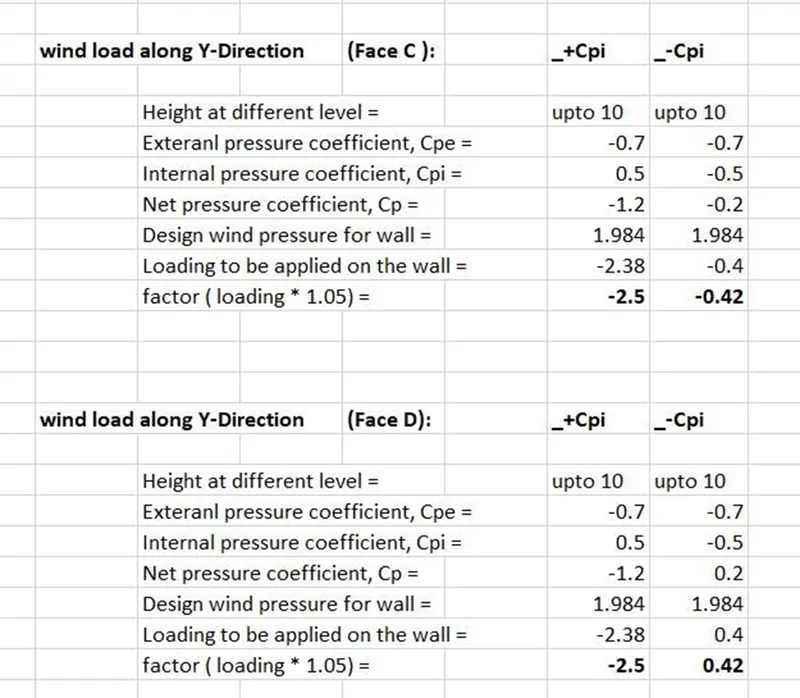
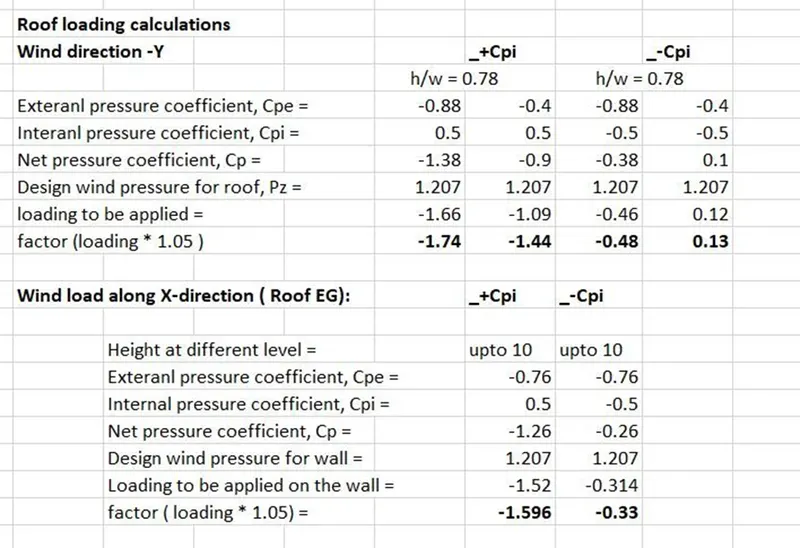
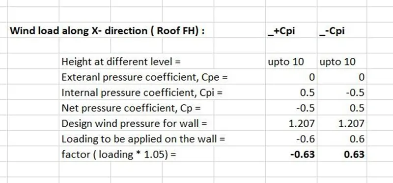
- Start applying the wind loads on the structure.
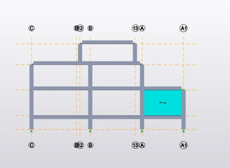
- Repeat the same process for all the sides.
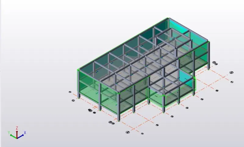
- Add roof panels to the structure and also add roof load.
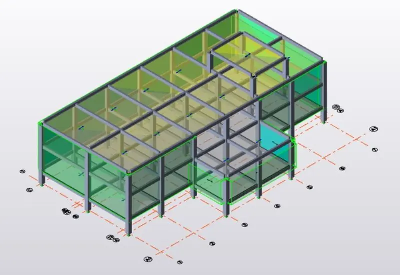
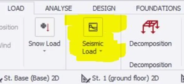
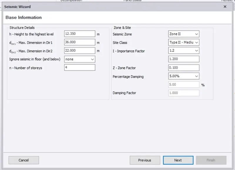
- Apply seismic load on the structure by selecting seismic wizard.
- Seismic wizard dialog box appears.
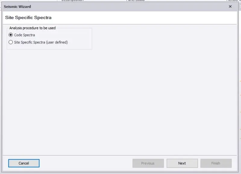
- Enter the required values required for seismic load calculation.
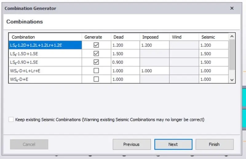
- Add loads which will be applied are visible now.
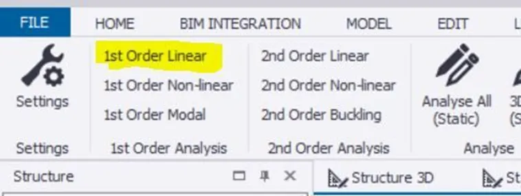
- Analyze the structure by selecting 1st order Linear option.
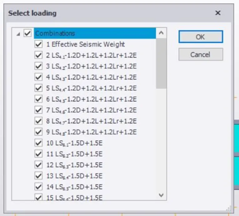
- Select all the loadings required for the analysis.
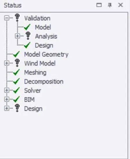
- Validate the model to check that there are no errors.
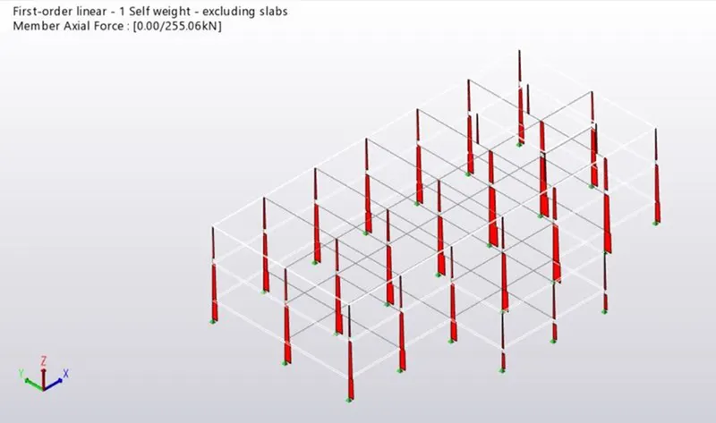
- Check the axial load diagram.
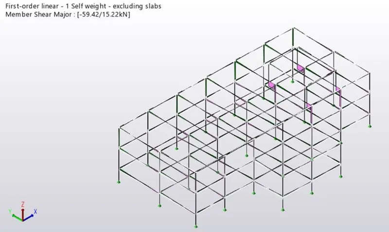
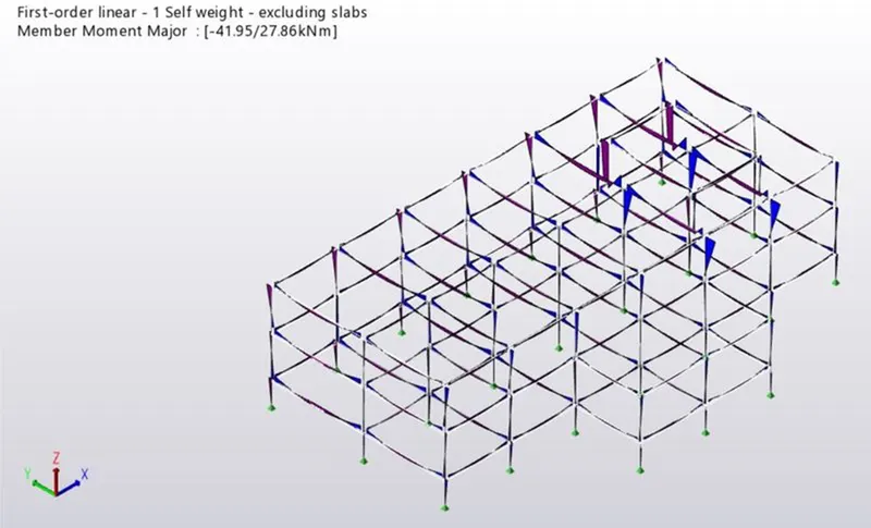
- Check the shear force and bending moment diagram.
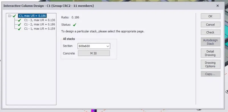
- Check eachand every coumn and perform interactive design.
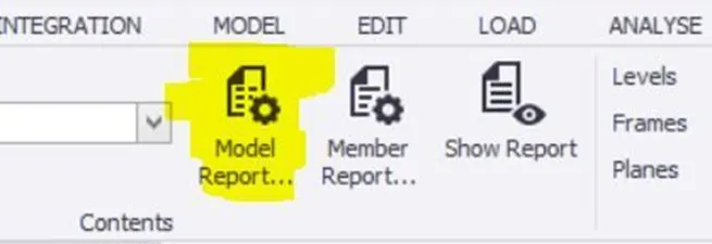
- Now we can model the structure by pressing on model report to obtain the reports.
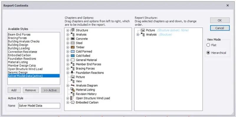
- Select what all reports we need.
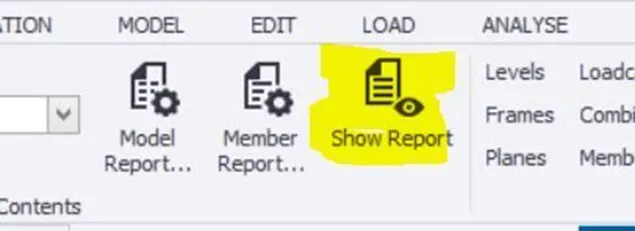
- Now for seeing the reports we have to press on show reports option.
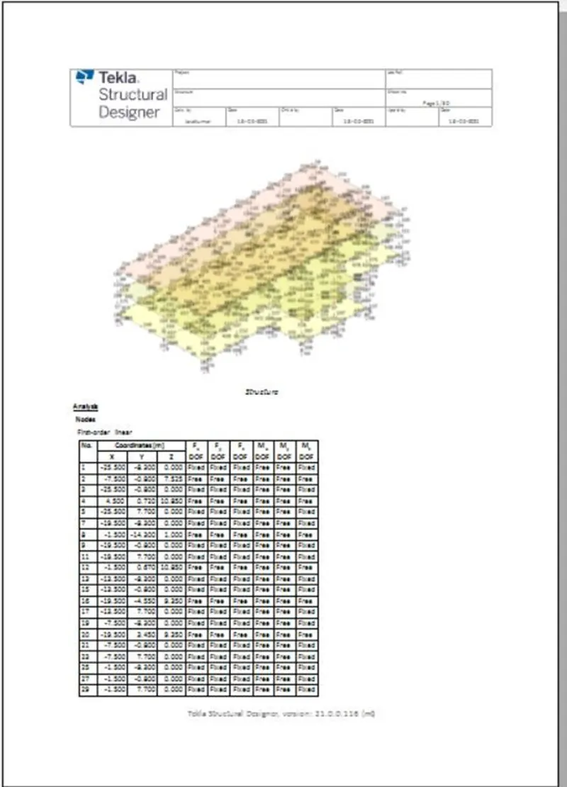
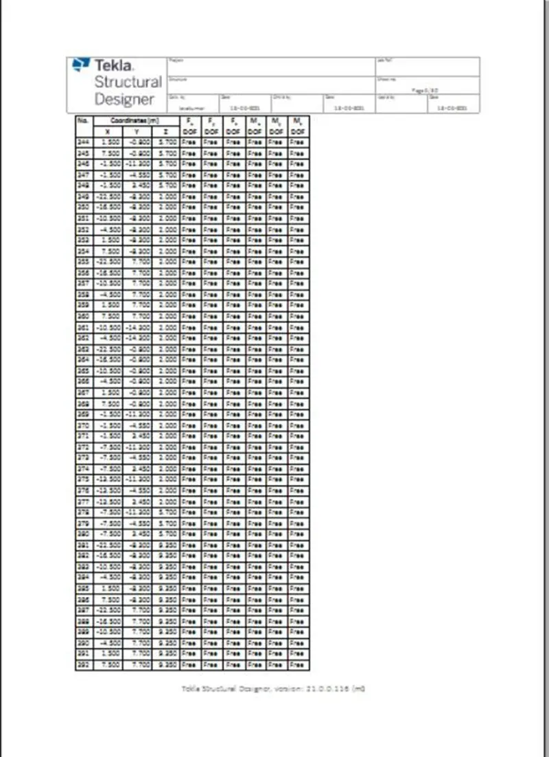
INTRODUCTION:- Tekla software is a building information modeling software tool to model all types of structures. It allows 3D modeling, 2D drawing and access building information. Tekla structure, basic building objects are provided and detailed further. Columns, Beams is modelled and properties are assigned such as materials, alignments, supports, design code etc. Certain configurations are assigned before modelling the objects such as design code, analysis type, scenes, materials etc. Loads cases and load combinations are generated, assigned for the structure using tekla and validation of those loads is an important part of Tekla Structural Designer as it ensures a valid model for the analysis and design routines.
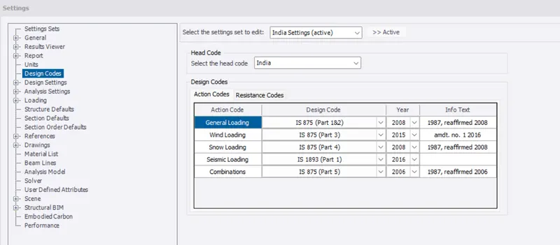
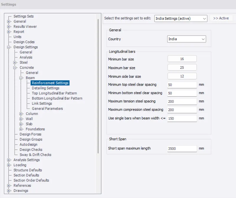
- Setting Design codes and reinforcement details for model. Indian code is assigned as "Head code"
- Beam details checked
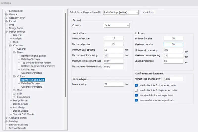
- Column details checked
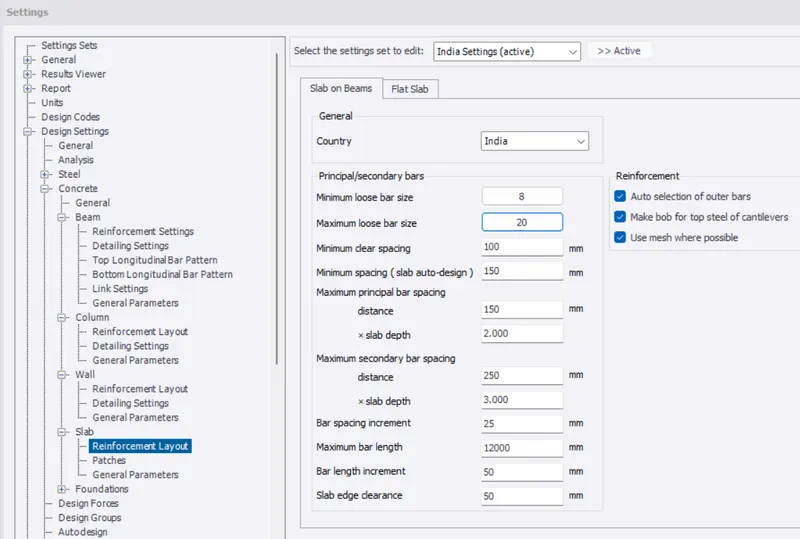
- Slab details checked
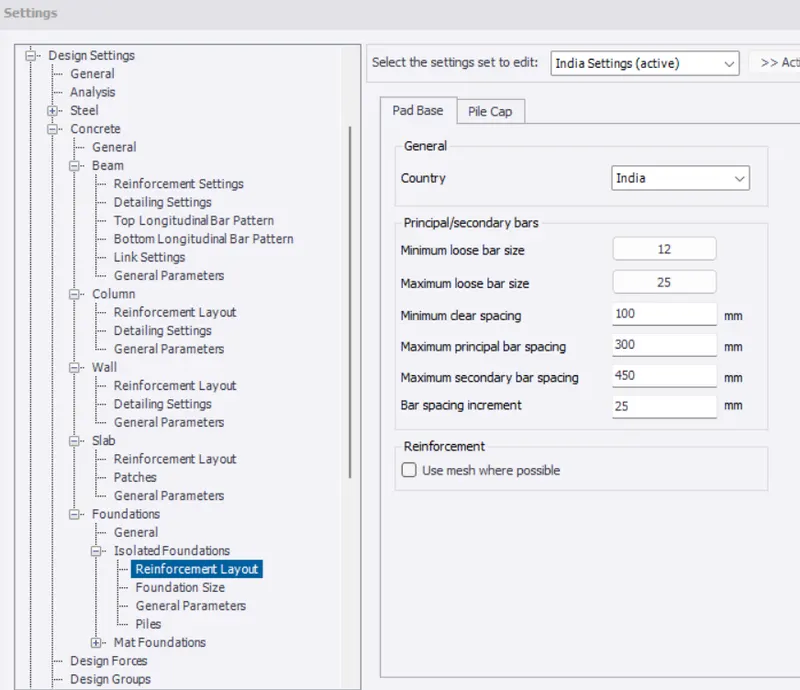
- Foundation details checked
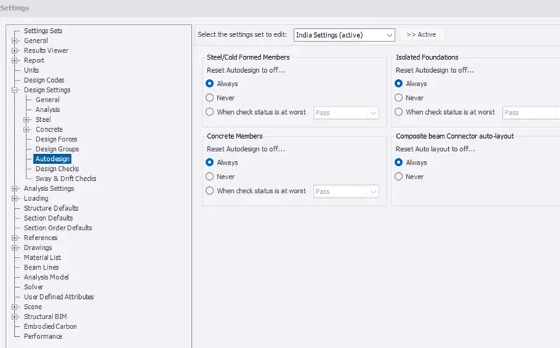
- Autodesign should be set off
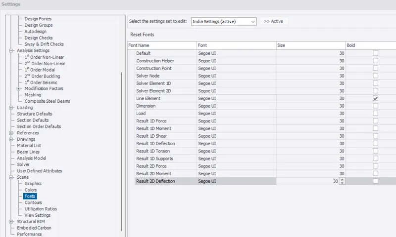
- Font size is set to "30"
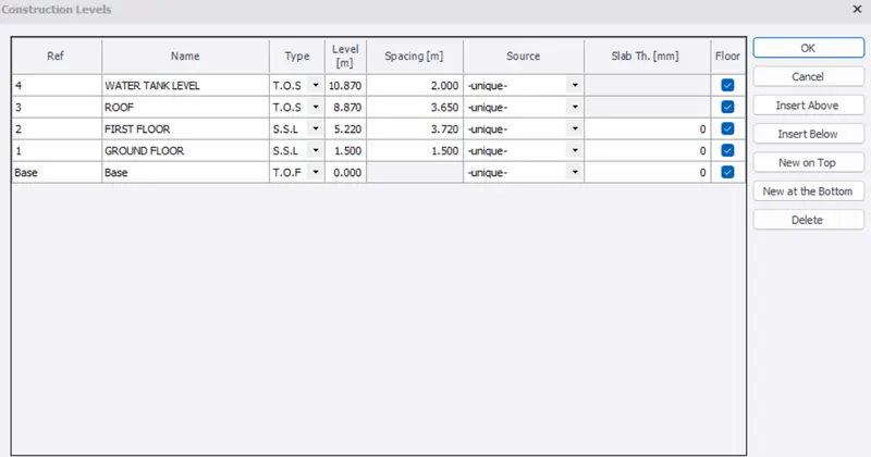
- According to the plan, various levels for RC buildings are assigned.
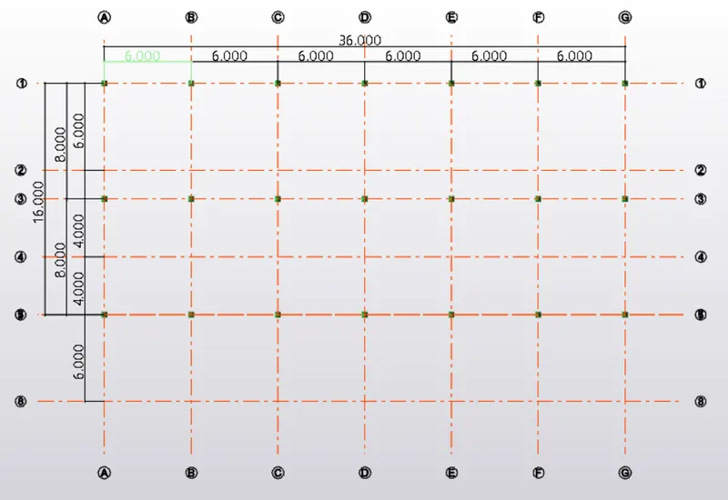
- Draw the grid lines according to the given plan
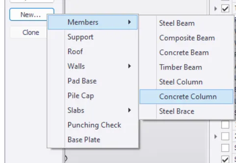
- To create members, Select "Manage property sets" in Home tab
- Select "New"
- Select Concrete column
- Pedestal column is created of size 600x800mm and Grade 30
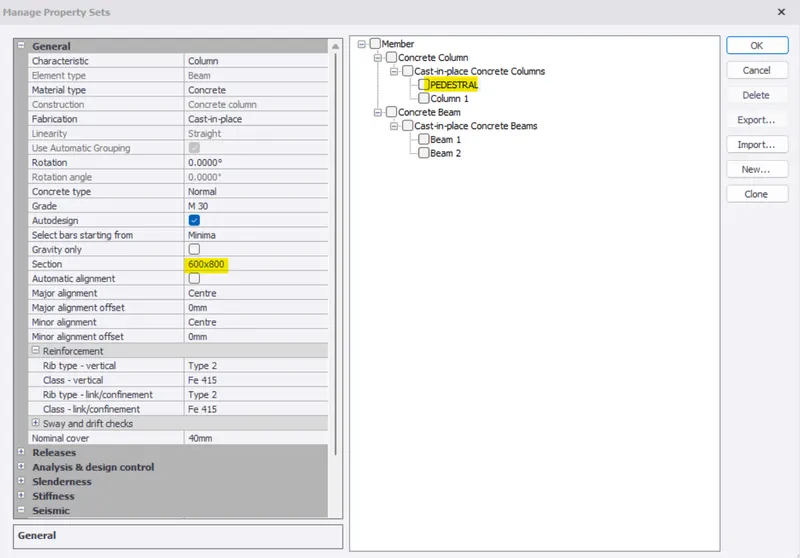
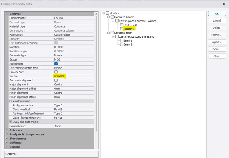
- Column of size 600x800mm is created
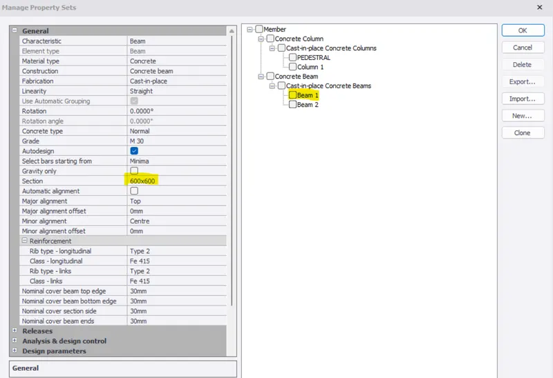
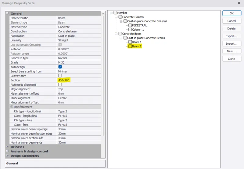
- Primary Beam size of 600x600mm and Secondary beam of size 400x400mm is created
- Now select column in "Model" tab and select pedestal
- Place the pedestal on the grid points
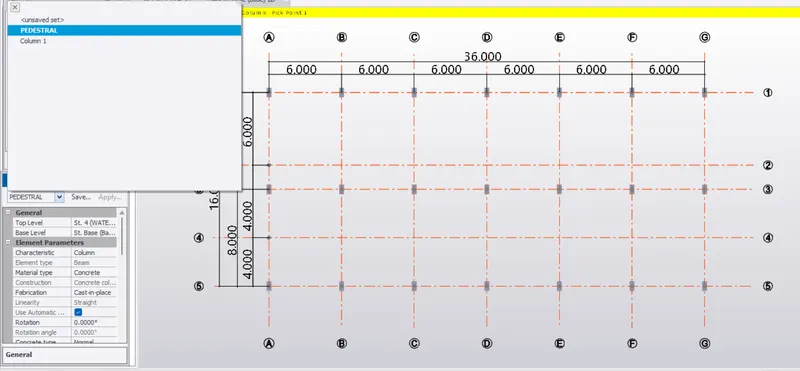
- Place the "Pedestal" in the base level(Top level is ground level and Bottom level is base)
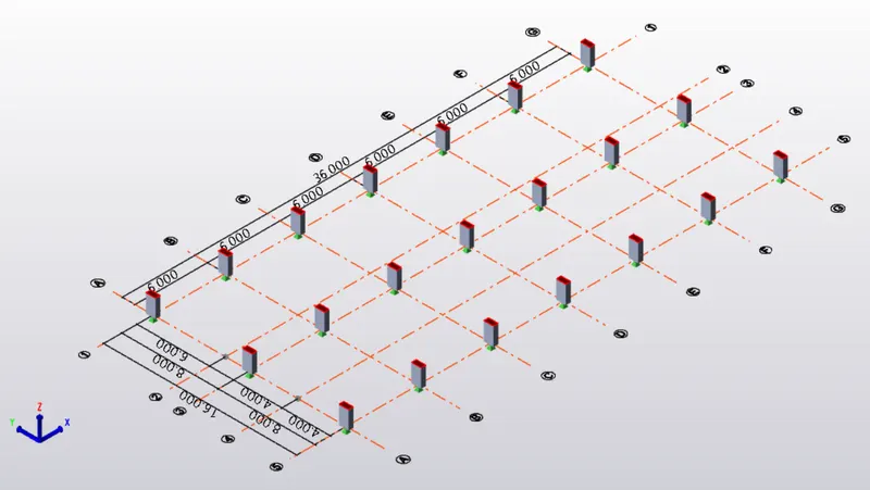
- Now place columns and primary beams according to the given plan
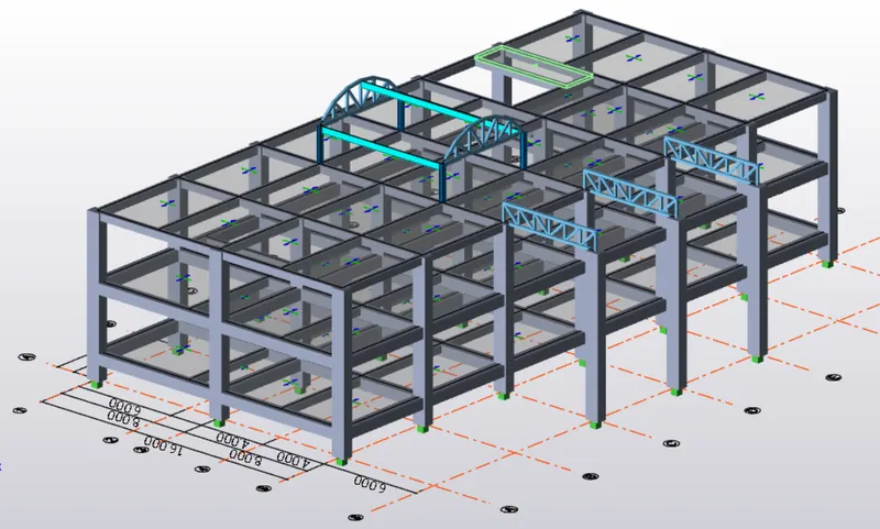
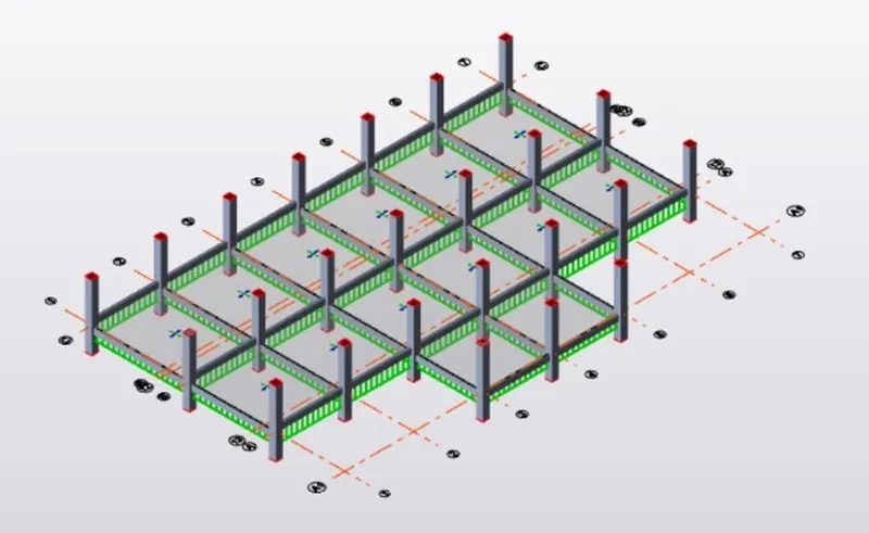
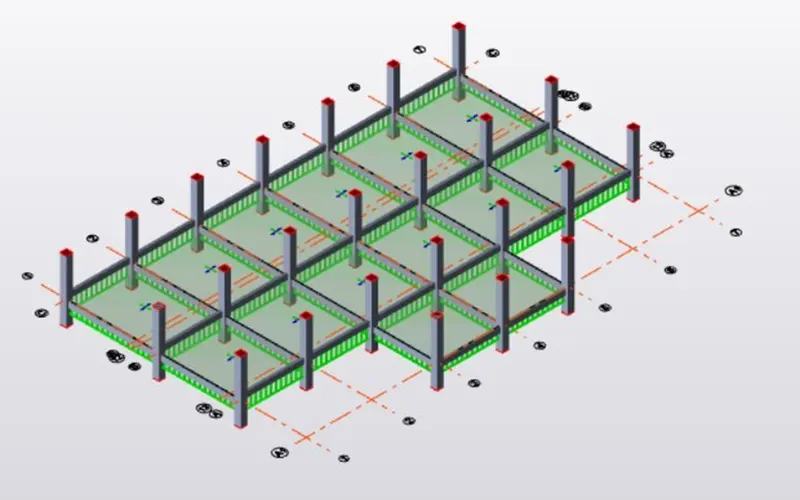
- Place secondary beams as shown below (Ground floor)
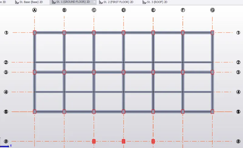
- Place secondary beams as shown below (First floor)
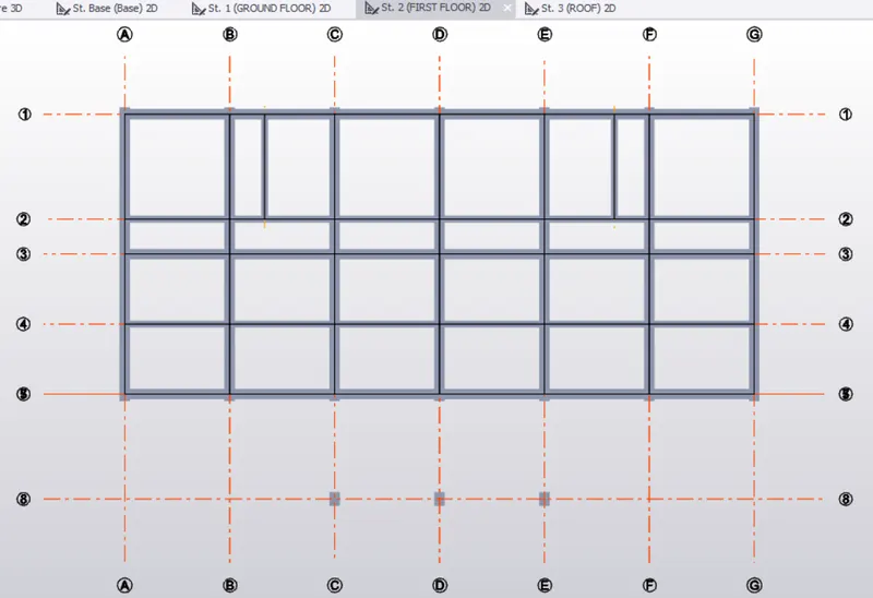
- Place secondary beams as shown below (Roof)
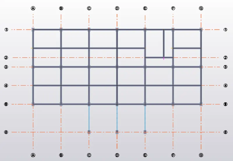
- Validate the model after placing all beams.
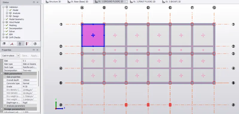
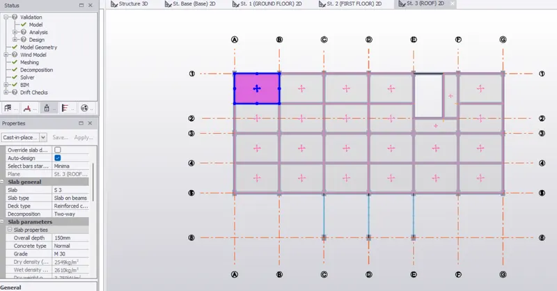
- Now select Slab on beams from model tab and place slabs on Groundfloor, first floor and roof
- Set X direction 90 degree and Overall depth of slab as 150mm
- Slabs on first floor
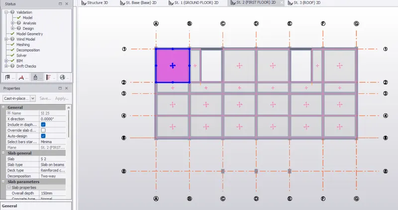
- Slabs on Roof
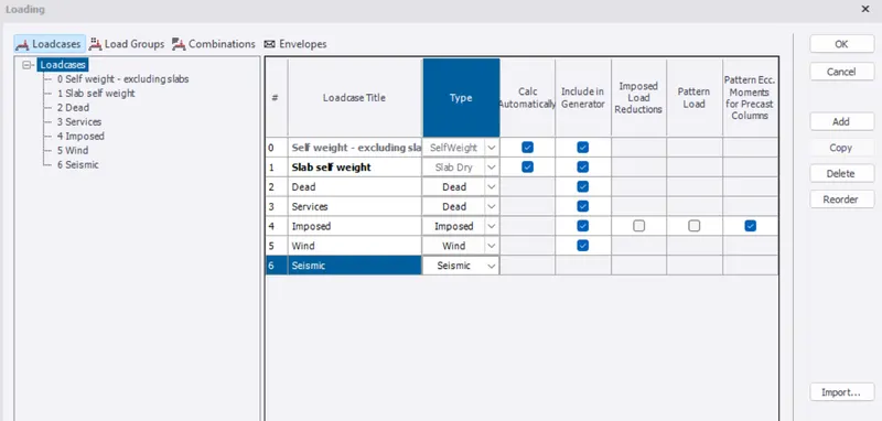
- Generate load cases
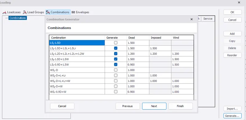
- Generate load combinations
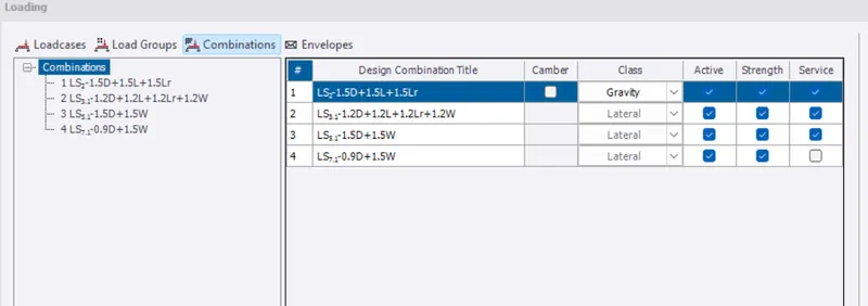
- Apply dead load, live load, Wind load and Seismic load
-
Slab load : Slab modelled in the software
Finishes taken as 50mm, Finishes = 50mm x 24 KN/m^3 = 0.05 x 24 = 1.2 KN/m2
Brick wall width taken as 150mm
Unit weight = 20 KN/m^3
Floor height (Ground floor to First floor) = 3.7m
Brick wall loading for ground floor = 20 x (150/1000) x 3.7 = 11.1KN/m
Floor height (First floor to roof ) = 3.650 m
Brick wall loading for first floor = 20 x (150/1000) x 3.650 = 10.95KN/m
- Brick wall loading for parapet wall on roof = 20 x (150/1000) x 1.5 = 4.5KN/m
-
Roofing load based on purlin size :1.5KN/m^2
Water tank load = 2mx10 = 20KN/m^2Ceiling loading 0f 0.3KN per sq m
-
- Select dead load at the bottom
- Now select area load from panel load (Load tab)
- Select area load = 1.2KN/m2 in ground floor and first floor and apply it
RESULT :
With the above steps we can design and model the structuer as per the given plan. We can add loads ( dead, live, wind and seismic) on the structure and analyze the structure.