Week 1 Challenge
1)
Aim :-
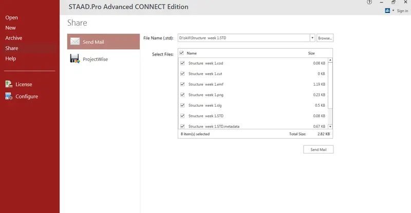
The steps involved to upload a .std file through web mail
Introduction :
- STAAD pro ( Structural Analysis and Deign program is the abbrivation for the STAAD it is the connected version new version used to analize the RCC structure and steel structure by using this software )
- It Include the GUI Graphic User Interface for Visualization and contains various design codes
Procedure :
- Open the software Staad pro in the landing page
- Click on share icon in
- Click on send mail
- Browse the file u want to share
- click on send mail
- Ensure that you are sign in
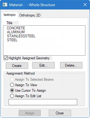
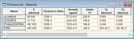
b) The type of materials used in staad pro
c) If you want to get the pictures in an external file ( like a word file, excel file, MsPaint etc.) go to the menu option Edit > Copy Picture, open the application you want and do a paste in there. Files saved through Take Picture option are not directly saved in common picture formats like bmp, jpg, png.
- press tab,the navigate arrow key to edit menu,then click on take picture
d) There are three methods of creating the structure data:
- Using the STAAD.Pro Physical Modeler interface,
- using the traditional STAAD.Pro analytical modeling interface,
- and using the command line
The physical model is used to draw structural elements as they are physically constructed. The program will then decompose this into an analytical modeling which is passed to the STAAD.Pro analysis and design engine when you run your model.
The analytical model is a finite element model of the structure which is typically processed directly by the analysis and design engine.
The command input file is a text file which contains the data for your structural model. This file consists of simple English language-like commands. This file is created for you behind the scenes for you when you model your structure using either the physical modeler interface or the analytical model interface.
e)
In STAAD.Pro Physical Modeler, the general order of operations is that you first select physical objects and then assign properties or perform some operation on the selection.
This differs from STAAD.Pro, where there are many tasks in which you select the operation, property, or specification first and then assign that to some list of model objects.
Comparison of Order of Operations
In this example, the operation of assigning profile sections to a selected set of beams is compared.
| STAAD.Pro Physical Modeler | Analytical STAAD.Pro Modeling User Interface |
|---|---|
| 1. Select the members which all have the same section. | 1. Add the profile you want to use from the Section Database. |
| 2. Select the Section tool in the Assign properties group on the Member ribbon tab. | 2. Select the member property in the Properties dialog. |
| 3. Select the profile to use and click OK. | 3. Use the cursor to click on members with this property |
2. The program contains a number of parameters that are needed to perform design as per IS 13920 2016. It accepts all parameters that are needed to perform design as per IS:456. Over and above it has some other parameters that are required only when designed is performed as per IS:13920 2016. Default parameter values have been selected such that they are frequently used numbers for conventional design requirements.
| Parameter name | Default value | Description |
| EUDL | None | Equivalent u.d.l on span of the beam. This load value must be the unfactored load on span. During design the load value is multiplied by a factor 1.2. If no u.d.l is defined factored shear force due to gravity load on span will be taken as zero. No elastic or plastic moment will be calculated. Shear design will be performed based on analysis result.(Refer note) |
| BRACING | 0.0 |
Beam Design
Column Design: Correspond to the terms "Braced" and "Unbraced" described in Notes 1, 2, and 3 of Clause 39.7.1 of IS456:2000.
|
| ELY | 1.0 | Ratio of effective length to actual length of column about minor axis. |
| ELZ | 1.0 | Ratio of effective length to actual length of column about major axis. |
| EUDL | None | Equivalent u.d.l on span of the beam. This load value must be the unfactored load on span. During design the load value is multiplied by a factor 1.2. If no u.d.l is defined factored shear force due to gravity load on span will be taken as zero. No elastic or plastic moment will be calculated. Shear design will be performed based on analysis result |
| FYMAIN | 415 N/mm2 | Yield Stress for main reinforcing steel. |
| FYSEC | 415 N/mm2 | Yield Stress for secondary reinforcing steel. |
b)
| Tool name | Description |
|---|---|
 Nodes Cursor |
Used to graphically select nodes. |
 Beam Cursor |
Used to graphically select beams. |
 Plate Cursor |
Used to graphically select plates. |
 Solid Cursor |
Used to graphically select solids. |
 Geometry Cursor |
Used to graphically select nodes, members and elements of the structure simultaneously.
To select nodes, members, or elements using the Geometry Cursor, simply click on the desired structural components. To select multiple nodes, members and elements, hold while selecting. We may also select the structural components graphically by creating a window on screen with the cursor around these components. |
 Members Cursor |
Used in Steel Design or Concrete Design to graphically select all those beams defined as a same member in the member set up of member design, simultaneously.
Members may be user defined or may be generated automatically using the Auto Form Member tool. To select all the beams defined as a same member using the Member Cursor, just click on one beam. The other beams having the same member name as the selected one will automatically be selected. To select multiple physical members, hold down while selecting. You may also select the physical members graphically by dragging a fence area around these physical members using the cursor. |
 Plates & Solids Cursor |
Used to graphically select both plate and solid elements. |
 (Select) Text |
Used to add comments and titles to pictures and result diagrams. The added text can be plotted, too.
The inserted text can be deleted, moved, and modified using the text cursor. Refer to the Insert Text on the Utilities ribbon for a detailed description on inserting text and modifying it using the text cursor. |
 Previous |
Selects the last objects selected if they have been deselected or if the selection set has changed. |
 Load |
Used to modify any load already applied on the model by double clicking it. When selected, the mouse pointer changes to the Load Edit Cursor. |
c)
To navigating the model view
The view window contains a unique control device called the Rotation Gizmo which allows you to select set view orientations or to orient the model in the view about the global axes.
- Click the Rotation Gizmo to display preset views. Click the Invert icon to display the reverse of these views.
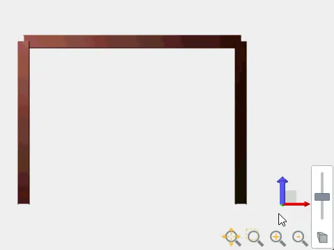
- Click and drag on the Rotation Gizmo axes to rotate the view about that global axis.
- Click on the zoom controls to zoom in or out of parts of the model. Click-and-drag the middle mouse button (i.e., scroll wheel) to pan the view.
- Click on the Perspective control to display the perspective switch and slider.
To navigating the model view
The view window contains a unique control device called the Rotation Gizmo which allows you to select set view orientations or to orient the model in the view about the global axes.
- Click the Rotation Gizmo to display preset views. Click the Invert icon to display the reverse of these views.
- Click and drag on the Rotation Gizmo axes to rotate the view about that global axis.
- Click on the zoom controls to zoom in or out of parts of the model. Click-and-drag the middle mouse button (i.e., scroll wheel) to pan the view.
- Click on the Perspective control to display the perspective switch and slider.
- Click the Rotation Gizmo to display preset views. Click the Invert icon to display the reverse of these views.
4. Explain the procedure to define a “Simply Supported” condition in STAAD Pro
ANS : Go to the support command in the tool palet command
- Click on create support command
- There we can get option like fixed support , pin support , Fixed but
- Enforced but support
- Cable support
- Inclined support
5. Name any five topics that you will include while creating DBR.
- DBR Design basis report
- To take up a project from the scrach to the end this is need
- To specify the data and compile data recived and analysis and design of structural element
- It contains the assumption and specification to develop the project
- It will help to avoid the scope and the creep that can derail the projec schedule and lead to budget overness
- Contains the general Column drawing
- Contains the projec planning
It also contains other parts also such as:
1. Length
The body of the report should be no more than ten double-spaced pages. Detailed design work, drawings, diagrams, engineering analyses, vendor part descriptions (e.g., gears, bearings), parts lists, and references should be referred to in the body of the report and then included as attachments.
- Purpose of the Report
The purpose of the report is to describe all aspects of your mechanical design project in a concise and thorough manner.
- Audience
Assume that your report will be read by your supervisor (D. Walczyk) and other design and manufacturing engineers working on this project.
- Organization
Title Page
Include the title of the report, your name, the class, and date of submission.
Executive Summary
Summarize what was asked for, what you accomplished and how it was accomplished. Include your main results and conclusions. Put this section first in the report but write it last. The summary should stand alone from the rest of the report. Limit it to one page (double-spaced) or less.
The Problem
Summarize the details of your chosen design project. In addition to the original problem description, include any additional tasks that you have decided to accomplish.
Design Specifications
List and fully explain the main design specifications used for this project. Many have already been prescribed in the project description.
The Concept
Using a neat hand sketch, CAD drawing, and/or schematic diagram, describe the final conceptual design for your project.
Detailed (Embodiment) Design Work
Provide an overview of the detailed design work you have completed. Report on each aspect of the detailed design work, reviewing the work completed in each area, and including sketches and the results of calculations, as appropriate. Include detailed component and assembly drawings (CAD preferably) and any supporting engineering calculations of only the parts you were asked to design in the problem statement as appendices. Whenever appropriate, make sure that you link the detailed design to the concept, design specifications, and problem.
Design Assessment
Summarize the results of your detailed design work:
Do your achieve and/or exceed all of the design specifications
What is the overall design recommendation to your engineering supervisor (i.e., D. Walczyk)? For example, should it be abandoned, further developed or pushed into production immediately? Why?
Finally, comment on what else needs to be accomplished, beyond what was asked for in the
design problem, before an actual prototype can be built.
References
References should be included. Use an acceptable format.
Appendices
Include in appendices all material that should be archived for further development of this project, i.e. early concepts, communications with vendors, details on vendor-supplied parts, engineering calculations, and detailed assembly and component drawings.
e) It means that it consist of different materials . i.e a steel deckhouse settled on a concrete shear wall
| Structure System | Geometry | Loading | Deform | Joint |
| Space | 3D | 3D | 3D | ANY |
| Plane | 2D | 2D | 2D | ANY |
| Frame | 2D | PARPEN TO XZ | PERPEN TO XZ | ANY |
| Truss | 3D | 3D | 3D | Pinned |
- Global Axis : Gloabal Axis is fixed in the coordiate system
- Local axis : local axis is variable
- This is used for the orientation of the beam with the load varible
- DBR Design basis report
- To take up a project from the scrach to the end this is need
- To specify the data and compile data recived and analysis and design of structural element
- It contains the assumption and specification to develop the project
- It will help to avoid the scope and the creep that can derail the projec schedule and lead to budget overness
- Contains the general Column drawing
- Contains the projec planning
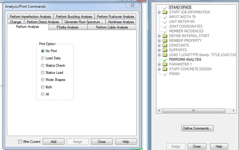
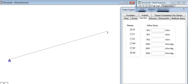
IN fixed condition the node or the end condition are fixed are restrained with the FX , FY, FZ and the moment are also restrained
In Fixed But condition the node are Fx and MZ are released as it is horizontal rolled support
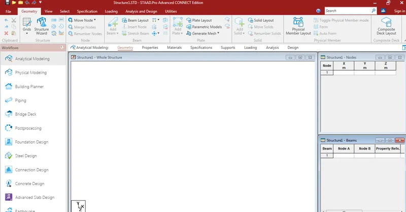
AIM : Creating a STAAD Model with the following Specification
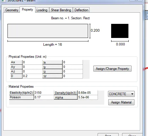
a. A beam of span 16mD
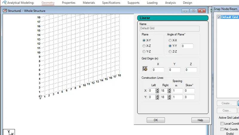
- Grid Dimension are to be given spacing as 1 m and in X and Y direction are 18 Grid
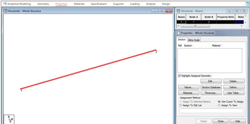
- Click on the Grid menu and Draw a beam of span 16 m
- For the node View click on CTRL +N or Right click and labels and view nodes
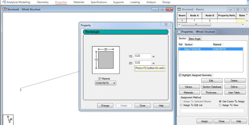
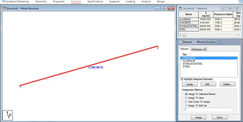
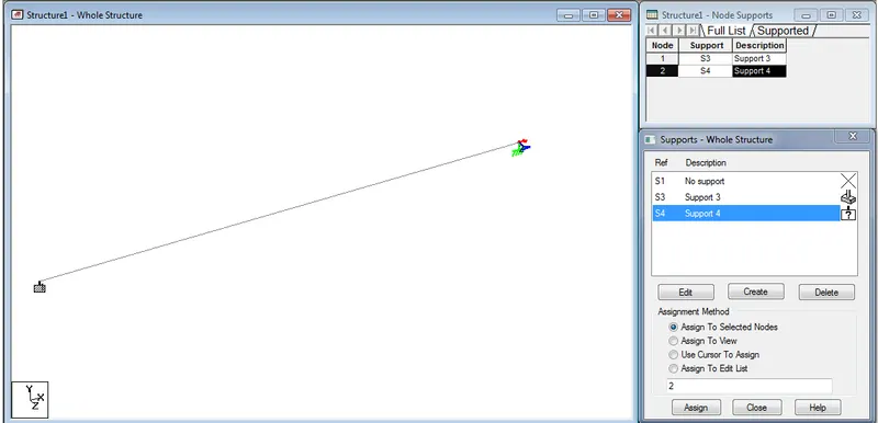
b. Support : Fixed on one end and Roller support(Horizontal) on the other end
Adding Fixed support and Roller support Horizontal on other end
c. A point load of 50 kN at the mid-point
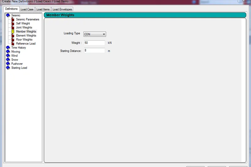
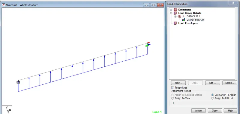
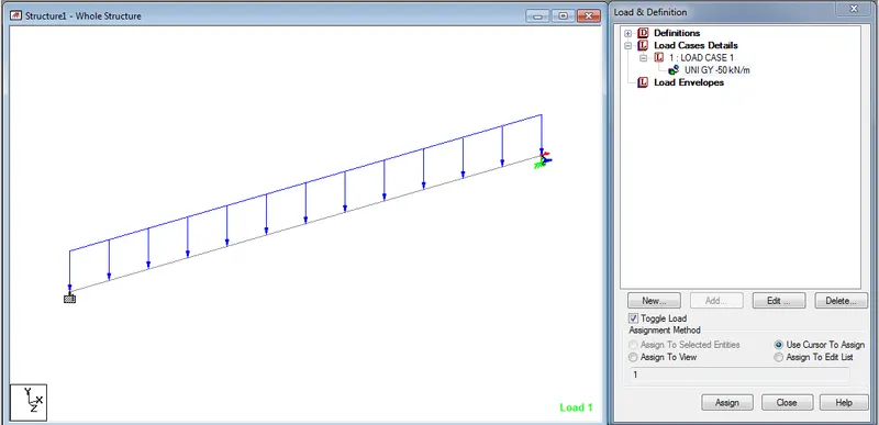
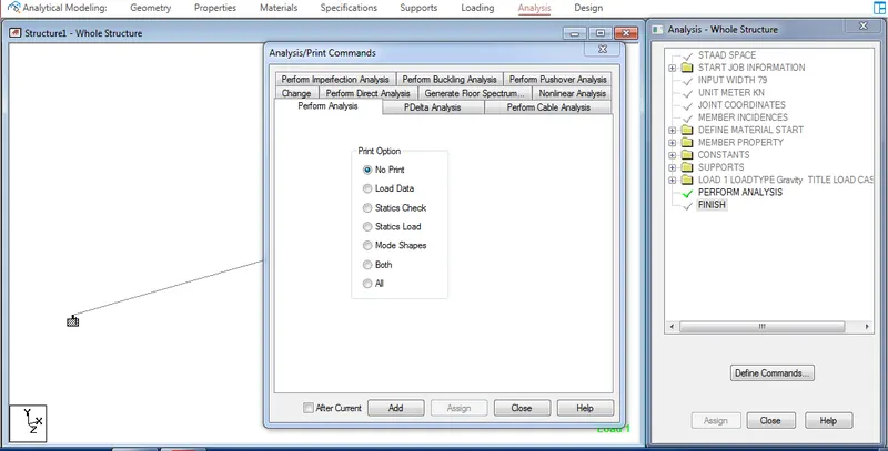
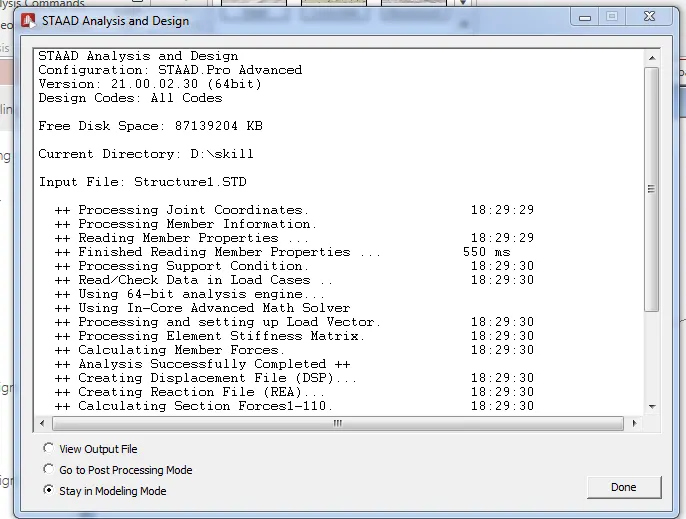
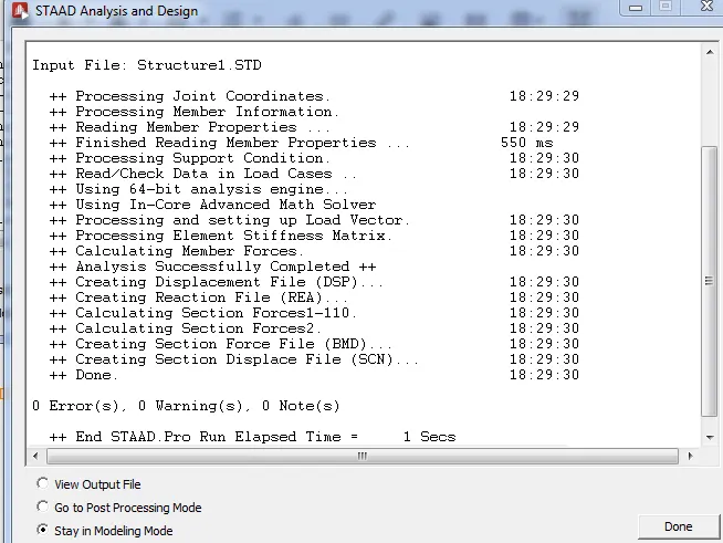
d. Draw SFD and BMD using software
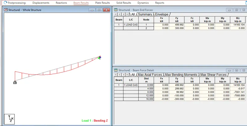
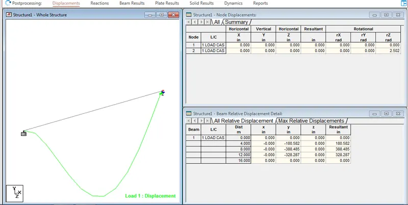
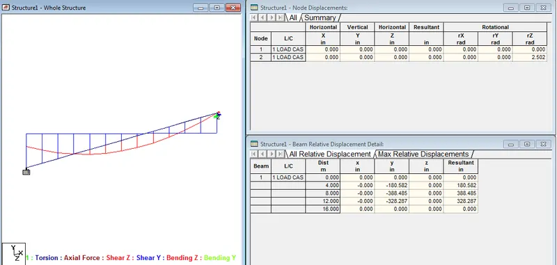
Result :-
The involved to upload a .std file through wepossible to capture images in STAAD Prob
2 )
Aim :-
Any six design parameter involved in RCC design
Procedure :-
Design per AISC 360-05, 360-10, and 360-016 (Unified) specifications is requested by using the CODE parameter. Other applicable parameters are summarized in the following Table. These parameters communicate design decisions from the engineer to the program and thus allow you to control the design process.
The default parameter values have been selected such that they are frequently used numbers for conventional design. Depending on the particular design requirements, some or all of these parameter values may be changed to exactly model the physical structure
RCC Column design is one of the most important concept in structural design. The reinforcement values of the column sections are depends upon the total amount of the vertical load acting on that particular column section. Basically loads which are related to combination of dead load and live load is initially transfer to slab section through that slab section it will distributed to beams and then to columns and to foundation. So if we design the column section with safety then entire building will be stable.
In my previous blogs I was explained how to design beam and slab section by using IS 456 code provisions so please read complete calculations with the following links
Beam design as per IS 456 code
One way slab as per IS 456 code
Two way slab as per IS 456 code
Design of columns as per IS 456 code basic formulas
The complete column design process as per IS code is determined by using below 3 basic formulas
- The minimum eccentricity values as per IS 456 code provision is calculated by using below formula in the column design we need to consider minimum or greater than 20 mm value as eccentricity value.
emin = (L/500) + (D/30) ≥ 20 mm
2. The calculation of main steel is determined by using the below formulae which is shown below
Pu=0.45fckAc+0.67fyAsc
3. The gross area, steel area required for the column section is determined by using below formulae
Ag=Asc + Ac
Basic key points taken in design
The following four key points are used in complete RCC column design
- Percentage of steel in RCC column is taken as 0.8% to 6% of the gross area.
- Minimum of 4 Bars are used in Rectangular column and 6 Bars in circular column
- Transverse reinforcement (pitch not greater than)
Least lateral dimensions
16d (d is small longitudinal bar diameter)
300 mm
- Diameter of the bar not less than
0.25 d
5 mm
Steps followed in column design by using IS456-2000
The following 4 steps are followed in RCC column design
- Calculation of Ac by assuming Asc
- Calculation of dimensions of the column by using Ag
- Calculation of reinforcement values of main steel Ac
- Calculation of transverse reinforcement
Example of column design by using IS456-2000 code
Design RCC column which carries 1200kN load with 3.5 m length. Assume M20 grade concrete and Fe415 grade steel
Since given load is 1200kN we need to make that to factored load
Factored load = 1.5X1200 =1800 KN
Step 1: Calculation of Ac by assuming Asc
By assuming the percentage of steel as 1% of the gross area
Asc =(1/100)Ag
So Asc = 0.01Ag
And also we have Ag = Ac + Asc
By substituting the Asc value we can easily get Asc
So Ac = Ag-0.01Ag
So finally Ac = 0.99Ag
Step 2: Calculation of dimensions of the column by using Ag
Since we have
Pu=0.45fckAc+0.67fyAsc
By substituting the values
1800X103=0.45X20X0.99Ag+0.67X415X0.01Ag
By calculation we can get Ag = 153971.173 mm2
By taking column as square section which is having a side area of the rectangle is a2.
So a2 = 153971.173 mm2
And Finally a = 392.39 mm
So, Take a as 400 mm.
Now the next step is checking for the emin
Since
emin = (L/500) + (D/30)
= (3500/500) + (400/30)
= 7+13.333
= 20.33 mm
Hence it is safe as per emin
Since the emin value is less than 20 mm so we can proceed to the design section of 400 mm X 400 mm column
Step 3: Calculation of reinforcement values of main steel Ac
Again we will use same Pu formulae for calculating the reinforcement values
Since
Pu=0.45fckAc+0.67fyAsc
By substituting the values
1800X103=0.45X20X(153971.173-Asc)+0.67X415XAsc
By calculating we can get Asc = 1539.711 mm2
So let us consider 1540 mm2 area
By assuming the 16mm diameter bars
The area of 1 single bar is (Π/4)162 = 201 mm2
Number of bars required is given by is given by (Asc/Area of 16mm bar)
N = 1540/201 = 7.661 no’s
Take approximately 8 no’s
So take 8 no’s of 16mm diameter bars as main reinforcement
Step 4: Calculation of transverse reinforcement
In transverse reinforcement initially we need to determine the pitch
Pitch is the least for following 3 values
- 16d =16X16 = 256mm
- Minimum lateral dimensions =400mm
- 300mm
The least of above three values is 256mm so we will take 256mm is the pitch for the column section design.
Diameter of bars calculation
The diameter of the transverse reinforcement is calculated by using two expressions shown below
- 0.25d = 0.25 X 16 = 4 mm
- 5 mm
So the final reinforcement use of 8 no’s of 16mm diameter main reinforcement and 6mm diameter bars of 256 mm center to center distance is used in the 400mmX400mm size with 1200kN point load.
The complete reinforcement details are shown in the below figure
Conclusions of RCC column design by using IS456 code
Well now the above explained concepts are related to the complete RCC column design as per IS 456-2000 code. The reinforcement details are calculated as per 4 steps Calculation of Ac by assuming Asc, Calculation of dimensions of the column by using Ag, Calculation of reinforcement values of main steel Ac and Calculation of transverse reinforcement
As per the calculation the reinforcement values obtained as use of 8 no’s of 16mm diameter main reinforcement and 6mm diameter bars of 256 mm center to center distance is used in the 400mmX400mm size with 1200kN point load.
RCC structures
RCC (Reinforced Cement Concrete) is a construction technology which evolved with the evolution of different structural materials in the 18th century during the Industrial Revolution.
Industrial Revolution brought in new technology which helped in the manufacture of various materials. The Architect Le Corbusier used RCC for various constructions. He believed that any shape and form was possible; if RCC is to be used.
RCC means Reinforced Cement Concrete, i.e., cement concrete reinforced with steel bars, steel plates, steel mesh etc to increase the tension withstanding capacity of the structure.
Cement Concrete can take up immense compression but weak in tension whereas steel is good in withstanding both tension and compression.
Here are some of the advantages of RCC construction:
- Materials used in RCC construction are easily available.
- It is durable and long lasting.
- It is fire resisting and not attacked by termites.
- It is economical in ultimate cost.
- The reinforced concrete member can be cast to any shape because of the fluidity of concrete.
- Its monolithic character gives much rigidity to the structure.
- Cost of maintenance is nil.
Here are some of its disadvantages:
- Scrap value of reinforced members is almost nil.
- Constant checking is required.
- Skilled labour is engaged in the work.
- The advantages of RCC outweigh its disadvantages.
This is one construction technique that made construction very easy and brought a boom to the field of construction.
A concrete slab is a basic structural elements used in building construction. The thickness varies between 100mm to 500mm for basic buildings. In the slab section reinforcement bars plays an important role in strength. The reinforcement in slab section are classified into two categories one is main reinforcement and second one is related to the distribution reinforcement. Design requirements in the RCC slab section will help to calculate the proper steel reinforcement under application of various loading conditions.
The following are the seven basic requirements considered in the slab design as per standards.
- Effective span
- Limiting stiffness
- Main reinforcement
- Maximum diameter of the bars
- Spacing of main reinforcement
- Distribution reinforcement
- Cover to the reinforcement
Effective span in slab design
The effective span is defined as the distance between the supports or clear distance between the supports plus the depth of beam or slab section.
In the slab section effective span is considered in two cases one is related to the simply supported slab and second one is cantilever slab. For the simply supported slab members the effective span value is taken as the sum of minimum clear span and effective depth values. In case of the cantilever slab section the effective span of the slab section is taken as the sum of the length up to the face of support and half of the effective depth.
Limiting stiffness
The value of the limiting stiffness varies for the three types of the slabs namely cantilever slab, simply supported slabs or continuous slabs.
For the cantilever slab the value of limiting stiffness is taken as 7 value, in case of simply supported section the value is considered as 20 and finally for the continuous slab section the limiting stiffness value is 26 as per the Indian standard code provisions.
Minimum reinforcement
The reinforcement values in the slabs are classified in to two types one is main reinforcement and second is distribution reinforcement as per the Indian standard code provisions 456-2000 the minimum slab reinforcement value in RCC slab is considered as less than of 0.5percentage.
Maximum diameter of the bars
The maximum diameter of the reinforcement bars in RCC slab is should not greater than (1/8) of slab thickness as per IS code provision standards.
For example let us consider a building which is having 120mm thickness of slab, for that particular structure we need to take maximum reinforcement bar diameter is (1/8) of 120mm which is 15mm.
In the same process let us consider a building which is having 150mm thickness of slab, for that particular structure we need to take maximum reinforcement bar diameter is (1/8) of 150mm which is 18.75mm. Approximately we will take 20mm maximum diameter of reinforced steel bars.
In the same process let us consider a building which is having 200mm thickness of slab, for that particular structure we need to take maximum reinforcement bar diameter is (1/8) of 200mm which is 25mm diameter.
Spacing of the main reinforcement bars
Basically the spacing is the center to center distance between the main reinforcement bars in slab section. The spacing of the main bars is depending upon the following two factors
- 3 times of the effective depth
- 300mm
The lesser of the above specified value is considered as spacing of main reinforcement in the slab section.
Percentage of distribution reinforcement
The distribution reinforcement is perpendicular to the main reinforcement in slab section. The percentage of distribution reinforcement in the RCC slab is not less than 0.15percenatge.
Cover to the RCC slab
The cover is the distance between the edge of slab to reinforcing bar. As per the standards the cover for the RCC slab section is considered as minimum of 20mm thickness.
Requirements of RCC Slab as per standards
| S. No | Design Requirements | Values as per standards |
| 1 | Effective span | For SSB = min clear span + effective depth
C/C distance For Cantilever = Length up to face of support + (1/2) effective depth |
| 2 | Limiting stiffness | Cantilever – 7
Simply supported -20 Continuous -26 |
| 3 | Main reinforcement | Less than 0.5% |
| 4 | Maximum Diameter of bars | Not greater than 1/8 of slab thickness |
| 5 | Spacing of main reinforcement | 3 effective depth and 300mm
Lesser of two is taken |
| 6 | Distribution reinforcement | Should not less than 0.15 percentage |
| 7 | Cover to reinforcement | Minimum of 20mm |
Result :-
As per the calculation the reinforcement values obtained reinforcement six design parameter involved in RCC design.
3)
Aim :-
The structure systems in STAAD Pro the coordinate system adopted in STAAD Pro software Procedure :-.
A STRUCTURE can be defined as an assemblage of elements. STAAD.Pro is capable of analyzing and designing structures consisting of frame, plate/shell, and solid elements. Almost any type of structure can be analyzed by STAAD.Pro.
- SPACE
- A3D framed structure with loads applied in any plane. This structure type is the most general.
- PLANE
- This structure type is bound by a global X-Y coordinate system with loads in the same plane.
- TRUSS
- This structure type consists of truss members which can have only axial member forces and no bending in the members.
- FLOOR
- A 2D or 3D structure having no horizontal (global X or Z) movement of the structure [FX, FZ, and MY are restrained at every joint]. The floor framing (in global X-Z plane) of a building is an ideal example of a this type of structure. Columns can also be modeled with the floor in a FLOOR structure as long as the structure has no horizontal loading. If there is any horizontal load, it must be analyzed as a SPACE structure.
Specification of the correct structure type reduces the number of equations to be solved during the analysis. This results in a faster and more economic solution for the user. The degrees of freedom associated with frame elements of different types of structures is illustrated in the following figure.
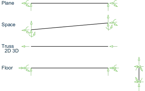
Degrees of freedom in each type of Structure
The advent of high speed computers & softwares is a boon to civil engineering as the daunting task of analysis & design is virtually computerized nowadays. Staad Pro Vi8 has become an essential software in civil/mechanical (structural) engineering world today. Nearly more than 95% of the Design Firms use Staad Pro.It can be used practically for all types of structures starting from concrete, steel to aluminum, timber and even piping design. Both static and dynamic analysis including PDelta, Pushover, Time History,Response Spectrum,Buckling Analysis etc. can be performed here. The analysis of structural systems which used to be manual a few decades ago, can now undergo several iterations with different alternatives with the help of computers. Hence the present day engineers are paying more attention to know how to use the software i.e., how to efficiently give the input to the computer and how to interpret the results from the computer output. As a result the engineers are now mostly entirely depending on the software for the analysis and design. But we need a skilled structural engineer to drive it otherwise we will be losing our understanding on the behavior of the structure and merely be working with numerical results thereby compromising with our engineering sense and also the business ethics part of our working culture.
Structural analysis is the study of behavior or effects on a structure when subjected to actions of external forces. Forces comprise various types such as seismic loads, dead loads, imposed loads, and many more.
To perform structural analysis, we implement various tools of basic and advanced mechanics. Some methods that we follow include:
- Equilibrium Laws
- Conservation of Mass and Energy
- Energy Theorems
- Slope Deflection Method
These methods are profoundly quantitative and analytical in nature.
Structural design is discovering the right sections of structural components to bear the forces and loads we subject them to without inflicting damage. Some structural designs include:
- Beams
- Columns
- Slabs
- Disc plates
- Bracing
- Bolts
- Stiffeners
- Welds
We might wonder that this subject did not have any traces of existence in the medieval eras; however, structures and monuments from those eras have withstood the test of time, thanks to the fundamentals of design.
Although we are now in a different time period, the reasons why we require the aid of structural designing remain just as critical:
- It is a core subject.
- It reinforces the buildings with extra safety and integrity.
- It makes the construction economically feasible by knowing the precise amount of materials required.
Applications
Structural design and analytics are used across various domains that include:
- Steel and Metals industry
- Power Sector
- Material Handling and Mining
- Automobile and food industry
- Real Estate
- Commercial Complexes
- Infrastructures like flyovers, bridges, and airports

STAAD.Pro is an analysis and design tool used for structural designing in civil engineering. It is a very renowned software used across the globe in sectors such as colleges, individual professionals, and various other firms.
Each member or surface has its own local Cartesian coordinate system which is also oriented using the "right hand" rule.
The longitudinal axis of a member is the first axis, with the positive axis taken from the i to the j ends (i.e, Ni and Nj). The second axis is the oriented such that the 1-2 plane is then parallel to the global Y axis. The third axis is then normal to the first and second local axes as defined by the right hand rule. The local 2 and 3 axes coincide with the two principle moments of inertia of the cross-section. In the special case of a vertical member (where the local 1 axis is parallel to the global Y axis; i.e., a column), the local 3 axis is then made parallel to the global Z axis and the 2 axis is oriented respectively.
| (A) | (B) |
Local coordinates of (A) a member with arbitrary orientation and (B) oriented vertically
For surfaces, the local x axis is aligned with the edge defined by the first two nodes of the surface (i.e., N1 and N2). The program then calculates the area of each triangle formed by any other nodes to determine the largest area. This triangle determines the plane of the surface and the local y axis lies perpendicular to the x axis within this plane. The third axis is then orthogonal to the surface as defined by the "right hand" rule.
Local coordinates of a surface
Result :-
The structure systems in STAAD Pro. A beam of span