Assignment 2-RADIOSS Engine File Editing & 3D Meshing Challenge
AIM : RADIOSS ENGINE FILE EDITING
PROCEDURE :
>First import the model
>There we have select "rad"file 0000.rad and then import
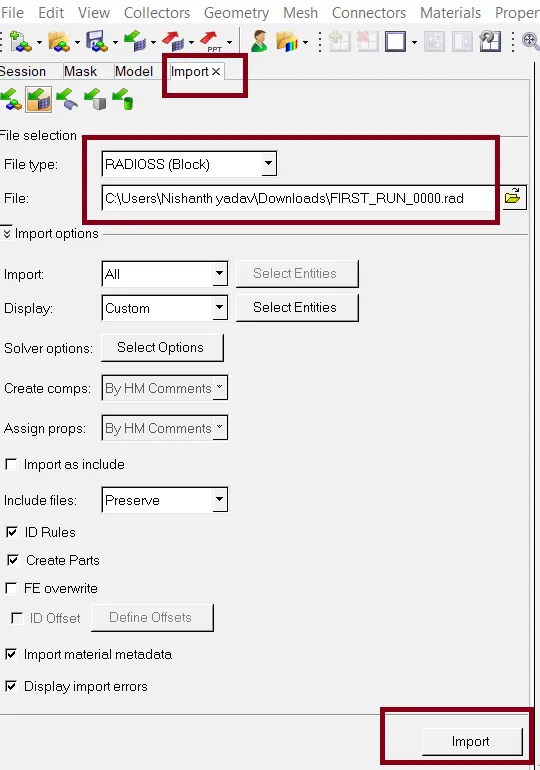
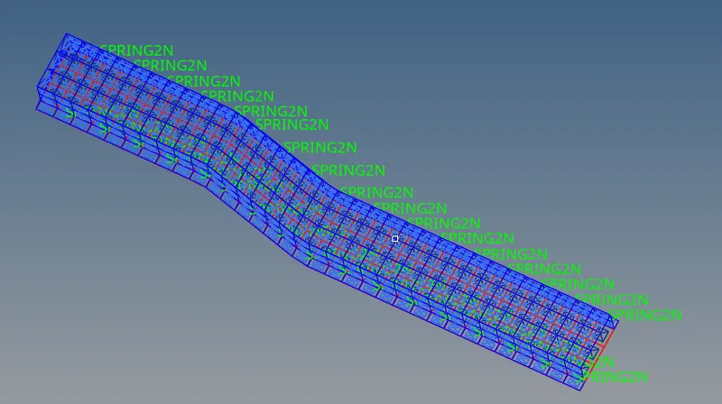
> As given following questions :
Questions:
1. check the material properties of the rail component and calculate the speed of sound in steel rail
2. The length of the rail is about 1000 mm.calculate the time takes for a shock wave to travel from one end of the rail to the other.
3.Time for sound to travel length of rail
4.Edit the engine file so that the stress wave can be monitored, moving from one end of the rail to the other during impact -this will require a termination time equal to the time it takes for the sound to travel the length of the rail(set on/RUN card)
5.Set the frequency of animation output to a time that will give 20 animation steps(/ANIM/DT)
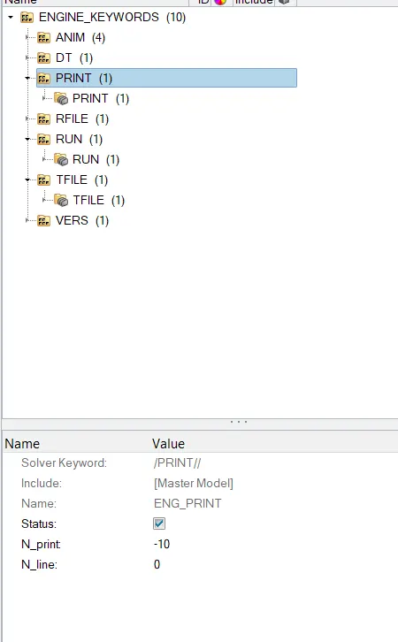
6.Change /print -10.
> The Starter file :
starter file is essentially called an input device , all the input details about the model set up like components ,meshnodes/element information ,materials laws, contact details, bondary conditions details etc.
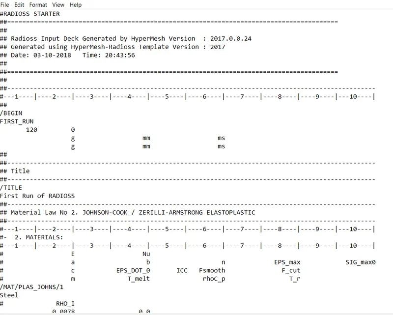
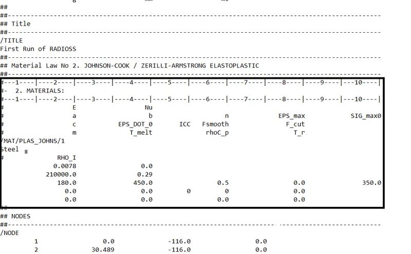
>The property add of material are :
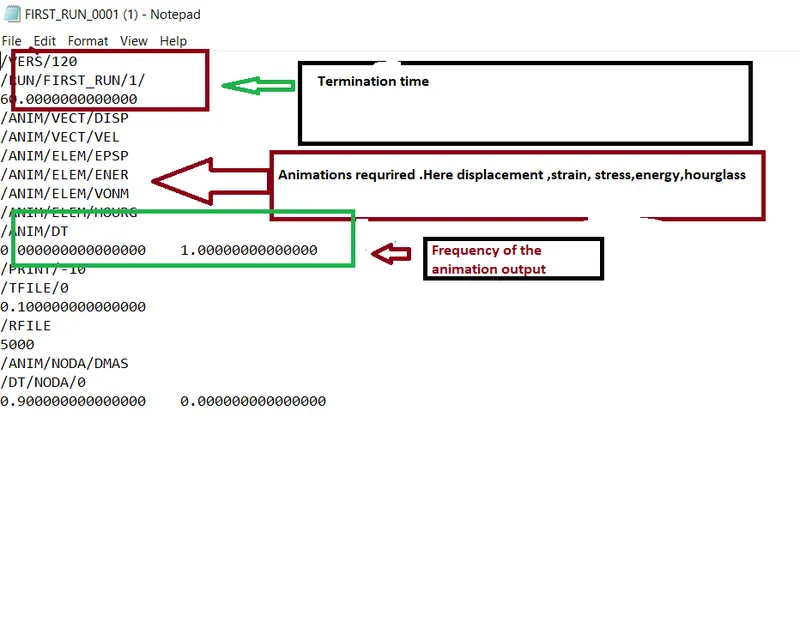
>ENGINE FILE :
Engine file is a file that contains the running the running instruction for the solver , it also contain the animation outputs expected from the model
>TIME STEP CALCULATION :
> The total response time is divided into much smaller time intervals called time step or increments,the equation are solved and the unknown are determined at (t +`delta(t)`) based on the knowledge of their values at time t.
>Time step is the requrired forces shock wave to propagate a cross the smallest distance of the element
>A run is solving of the model from 0 to the user defined end time values
>A Explicit solving is stable `Delta(t)
WHERE ,`Delta = l/c`
lc = critical element length
C = speed of sound
>Now answering of questions :
>(1)check the material properties of the rail component and calculate the speed of sound in steel rail
>Now we will go to property and check the values
> speed of sound(c) =`(E/del)^(1/2)`
where, E = Youngs modulus
`del`= density
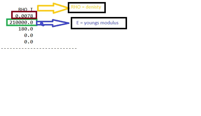
>Then,speed of sound(c) = `(21000/0.0078)^(1/2)` = 5188.745m/s`
2. The length of the rail is about 1000 mm.calculate the time takes for a shock wave to travel from one end of the rail to the other.
>Shock wave to travel at the sped of sound , then
>Shock wave speed = speed of sound (c)= 5188.745
>Then we have to calculate the time taken for a shock wave :
>time(t) = Distance /speed of shockwave
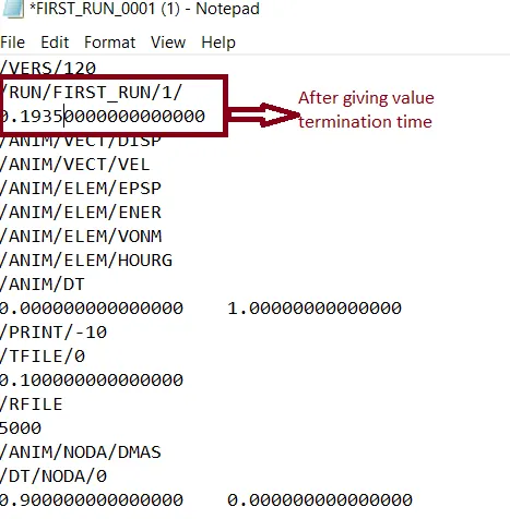
>time(t) = `1000/5188.745 = 0.1935s`
3.Time for sound to travel length of rail :
> time (t) = Distance/speed of sound
>time(t) = `1000/5188.745 = 0.1935s`
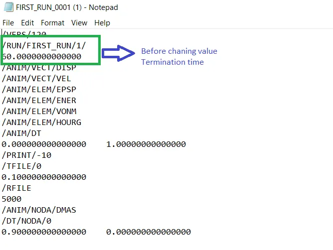
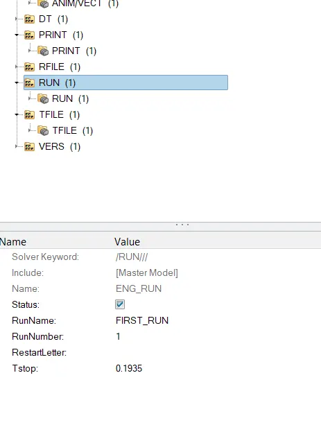
4.Edit the engine file so that the stress wave can be monitored, moving from one end of the rail to the other during impact -this will require a termination time equal to the time it takes for the sound to travel the length of the rail(set on/RUN card)
> Then we have to give the termination value :
>Now, after giving value :
5.Set the frequency of animation output to a time that will give 20 animation steps(/ANIM/DT)
>time frequency = time / no.of revolutions
>time frequency = `0.1935/20 = 0.009675`
>Just open the file 0001rad file and edit end time value of time frquency
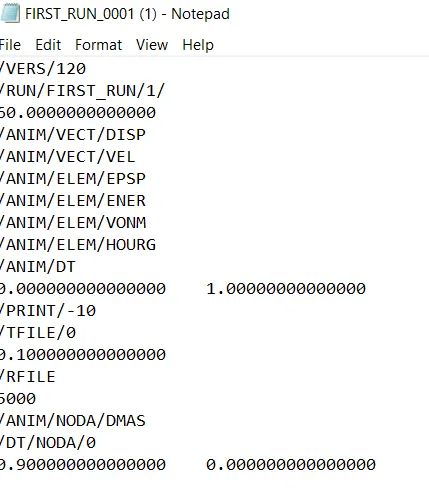
>After giving value :
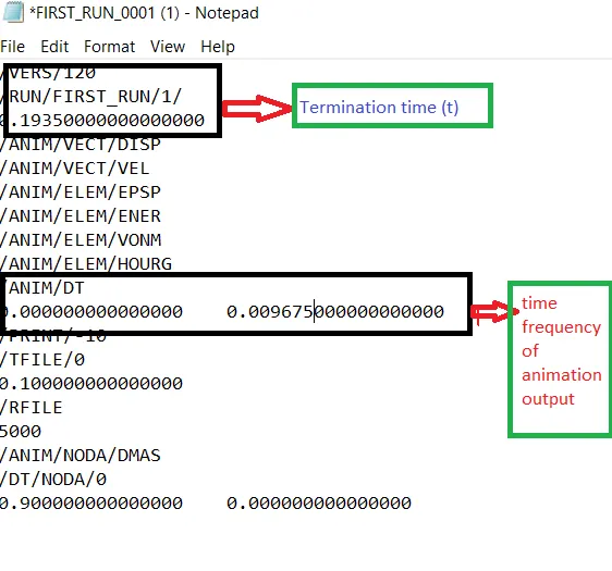
>To see of directly in the solver view :
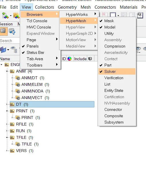
>The value changes are :
>Time frequency of animation output :
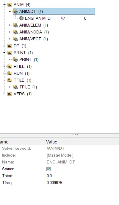
>The engine run file Tstop value ;
6.Change /print -10.
AIM : MESHING THE HOUSE PART BY TETRA ELEMENT
PROCEDURE :
>Import the model geometry
> conversion of 2D tria elements into tetrahedral elements, by using (tetra mesh panel)
>Import model
>Given housing component
>Model 1
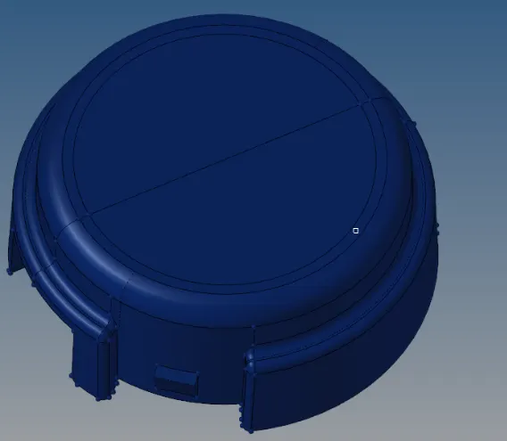
>By topology view :
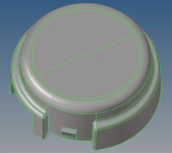
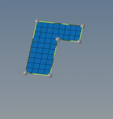
>First given surface, generating the 2D mesh with auto mesh option in 2D panel
>See the given length of values min, and maximum and target length of element
>After generating the 2D mesh, Then go with Tetra mesh,
>Select-3Doption-tetramesh-select trias and quads option -and mesh
>Give the element size

>Check whether generated or not of 3D mesh
>While i was deleting the few of elements , then i was checking
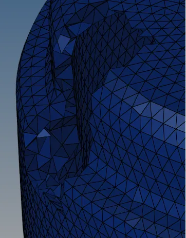
> Then, Finally check the quality of parameter (Shortcut key f10)

>Checking with 3D panel - test collapse
>Then check the status bar, there visible of failure elements
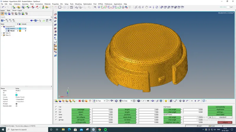 v
v
MODEL 2 :
>
>Then i was going with option utility
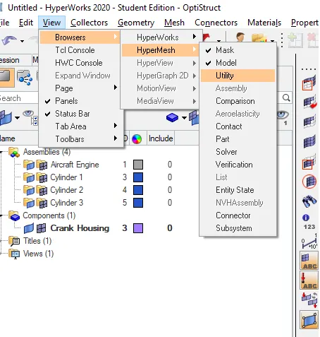
>Then go with option of Geome/mesh
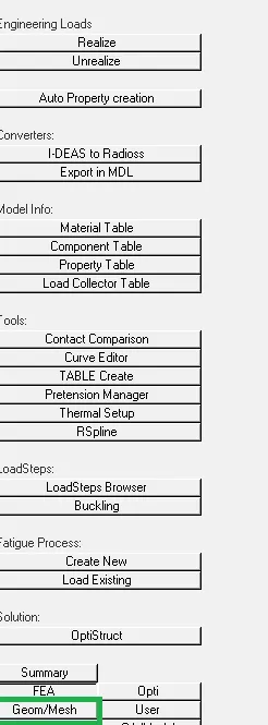
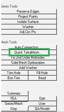
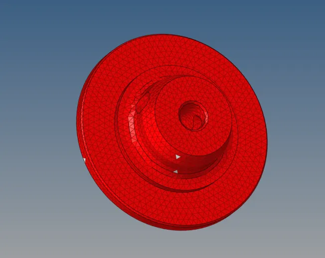
>Click the geom/mesh option(visible of mesh tools - quick tetra mesh)
>
>CONCLUSION :
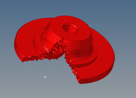
>Generated of 3D solid tetra element
>Generally, above of 6mm thickness object the thickness is not uniform
AIM : MESHING OF ARM BRACKET (3D MESHING)
>PROCEDURE :
>Import the model
>so, as we know of above 6mm thickness is the not a sheet metal ,solid element are used from meshing
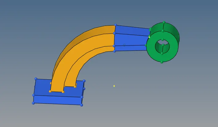
>Given model arm bracket :
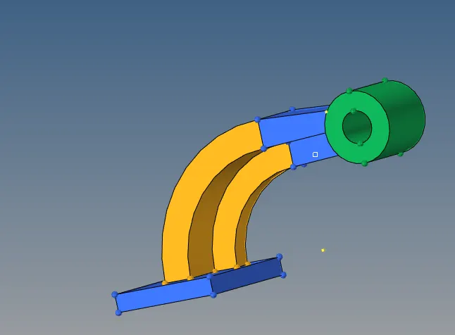
> Now see as the wire frame mode :
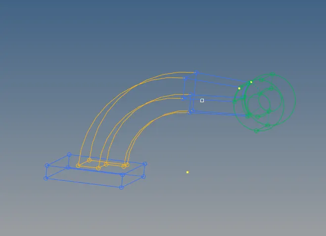
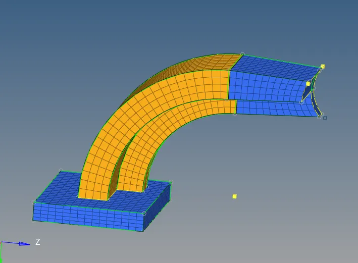
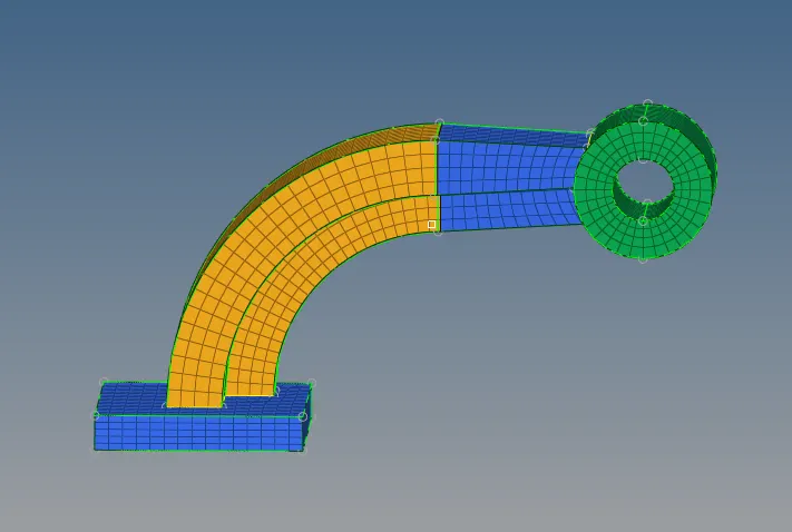
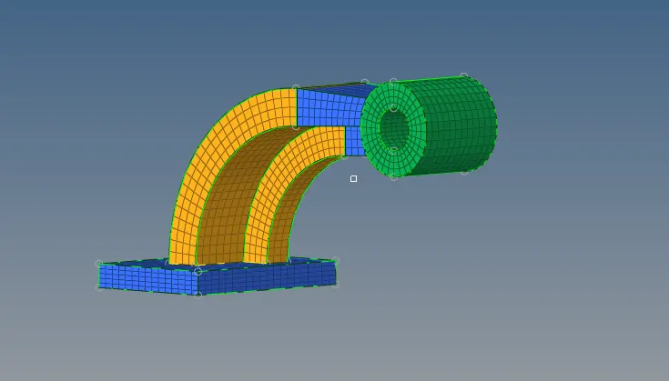
>The arm bracket containg four of different components,base ,arm curve and arm straight and a boss.
>Firstly go with step wise (Base):
>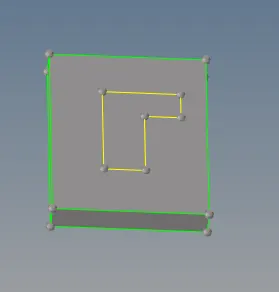
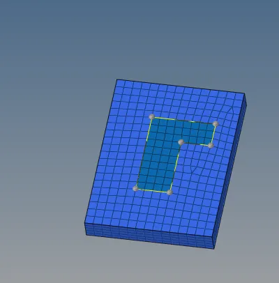
>The given element size 10 >2D>automesh>meshed by selecting of surface
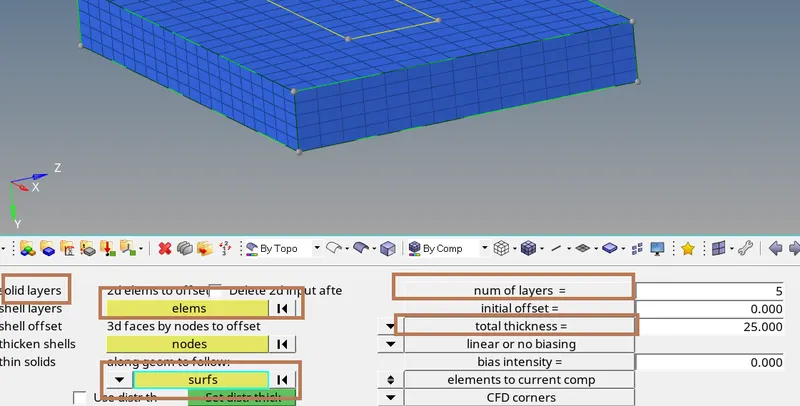
>Then,now go with 3D pannel >Elemt offset
>Selected the surface and meshed of it >
>Then give the no of layer and total thickness
> Now arm curve to mesh , then we have to need 2D shell element , because to "spin" element arm curve
>
>Now we need a to spin element, to mate arc center point, by based on point we easily generate of spin element
>Go with gem>nodes>seleted

>Now finally we created a arc center by using >gem>node
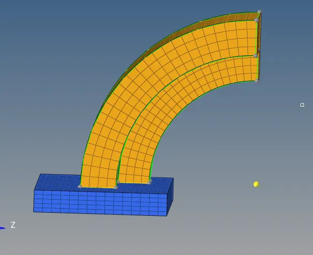
>Then go with 3D>spin option
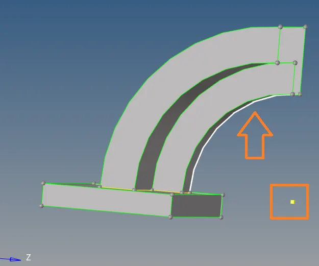
>Here we have to give angle of arm cruve spin,and no of on spin

>
>After that we need to extract of face of component of arm curve component ,because to mesh arm straight end of the 2D mesh needed ,then we have to use after the 3D pannei
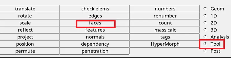
>By using the "tools" menubar option
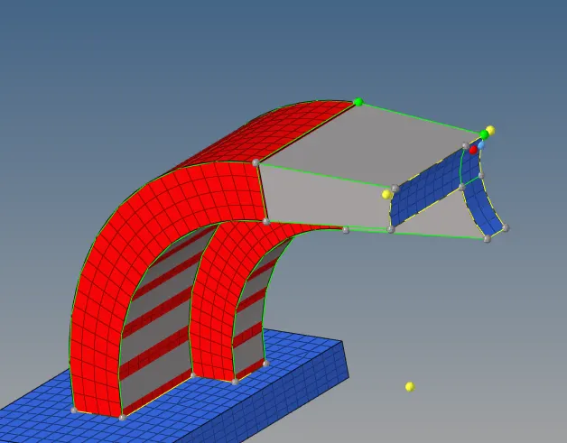
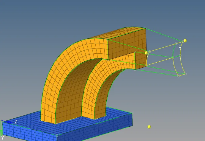
>Then go with 3D>linear solid to be meshing the 3D straight arm

>Then by select the element by face option
>Given correct alignment nodes direction n1,n2,n3 and density layer
>LINEAR SOLID OPTION :

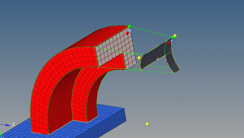
>The next component BOSS , the option is used to mesh the component by "SOLIDMAP"
>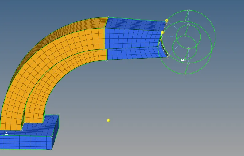
>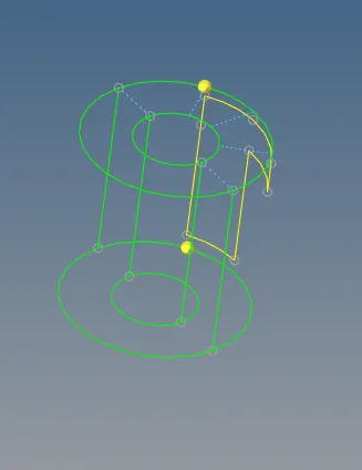
>One of surface side to mesh of boss component 2D shell element
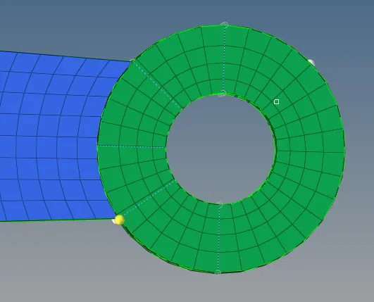
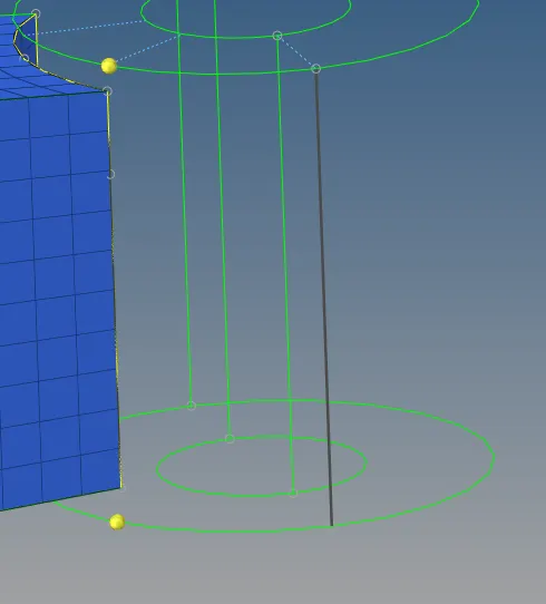
> To Give the nodes path conductivity to check with straight arm and boss component
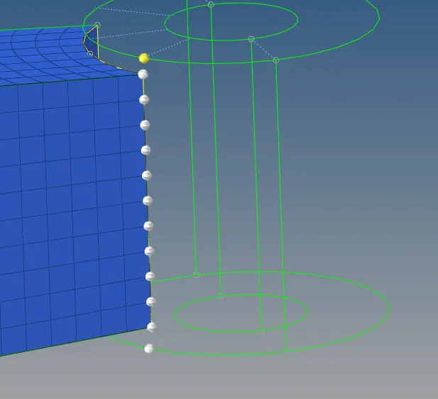
>To select the line of any the vertical line of boss component
>The final model of entire hexa meshed
AIM : GIVEN OF FILE MESH AND CONNECTS OF 1D ELEMENTS
PROCEDURE :
>Import the file STP format
>Given of two plates surface between connects of 1d elements
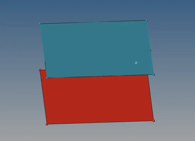
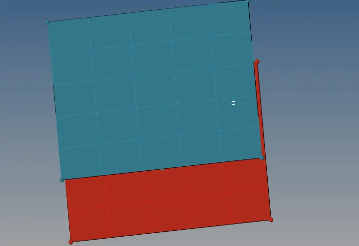
> The meshing of both sides plates :
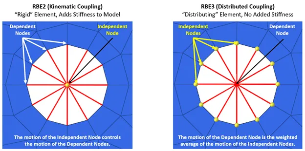
>CREATING RB3 AND RB2 ELEMENT :
>Both elements "look" the same, in that they have a single node connected to one or (usually) multiple other nodes. The difference is that the RBE2 element adds (infinite) stiffness to the structure, while RBE3 elements "distribute forces" around the connected nodes, without adding any stiffness.
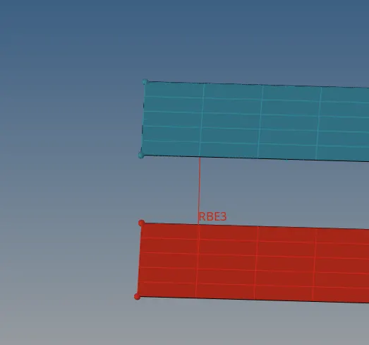
>As now crearted of RB3 (Rigid body element ) between two plates :
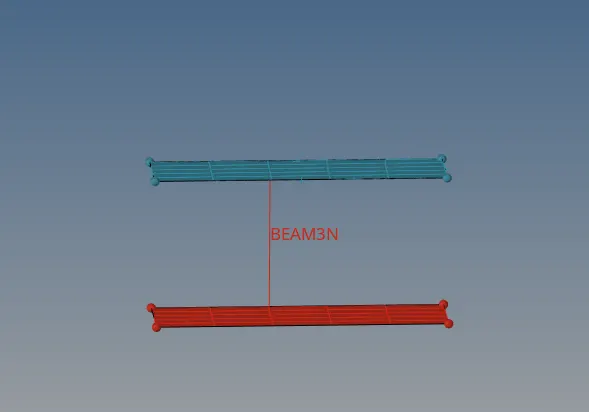
>BEAM ELEMENT :
>A beam element is a slender structural member that offers resistance to forces and bending under applied loads. A beam element differs from a truss element in that a beam resists moments (twisting and bending) at the connections. These three node elements are formulated in three-dimensional space
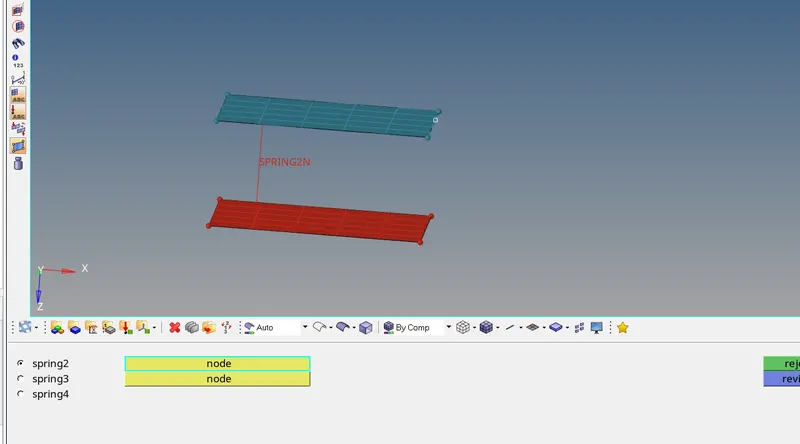
>SPRING ELEMENT :
>The spring element is a one-dimensional finite element where the local and global coordinates coincide. It should be noted that the spring element is the simplest finite element available.
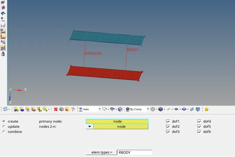
> RIGID BODY :
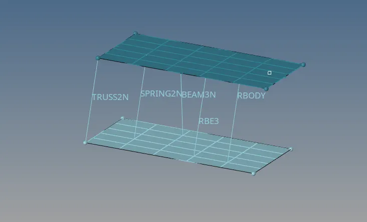
>And finaly all connects of 1d elements are :
>CONCLUSION :
>Undestand how to calculate of termination time , time frequency
>Undestand how to edit the radioss file "engine" and "starter"file (0.000radfile and 0.001rad file )
>Undestand how to calculate the speed of sound of different materials and time step and time frequency
>Undestand how to import the solver disk in radioss
>Undestand 3D meshing (TETRA AND HEXA)
>Creating of 1D connects of Bar,Beam,Spring,Rod,Rb3,Truss