Week-7 Challenge: DC Motor Control
OBJECTIVE:
1. A. Explain a MATLAB demo model named ‘Speed control of a DC motor using BJT H-bridge’.
B. Comment on the armature current shoot-up from the scope results.
C. Refer to the help section of ‘The Four-Quadrant Chopper DC Drive (DC7) block’. Compare it with the H-bridge model.
2. Develop a 2-quadrant chopper using simulink & explain the working of the same with the relevant results. (Refer to article - Multiquadrant operation of motor )
3. Explain in a brief about operation of BLDC motor.
A. Explain a MATLAB demo model named ‘Speed control of a DC motor using BJT H-bridge’.
>MODEL:
>Explanation:
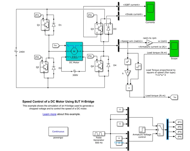
- The switch block circuit is connected at bottom of the model with the input signal is connected to the demux block and extract off several output signals as p1,p2,p3,p4
- When Q2 and Q3 are occurred of negative voltage is applied to the motor and diodes as D1-D4
- As per positive terminal as Q1andQ4 as a voltage applied to motor and diodes D2-D3
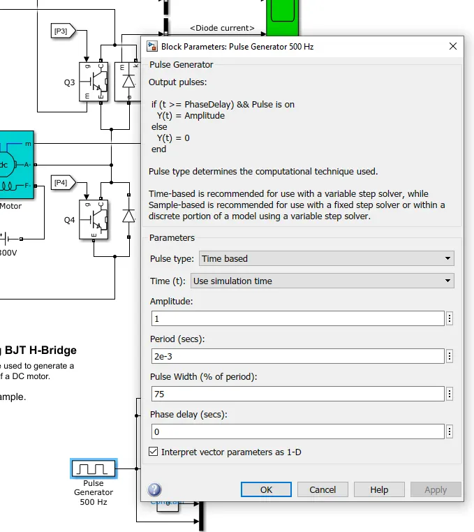
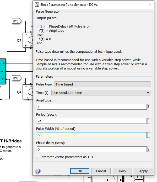
- Where the input signal voltage is supplied with a pulse generator
- The H-bridge consists of 4BJT/diode Paris, Q1 Q2 Q3, and Q4 respectively
- Q1 and Q2 are forward monitoring
- Q3 and Q4 are reverse monitoring
B. Comment on the armature current shoot-up from the scope results.
>OUTPUT:
SCOPE RESULT :
>Observation:
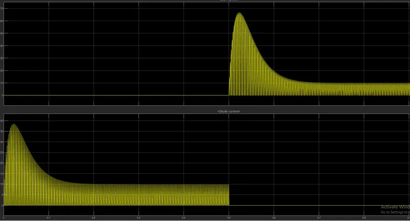
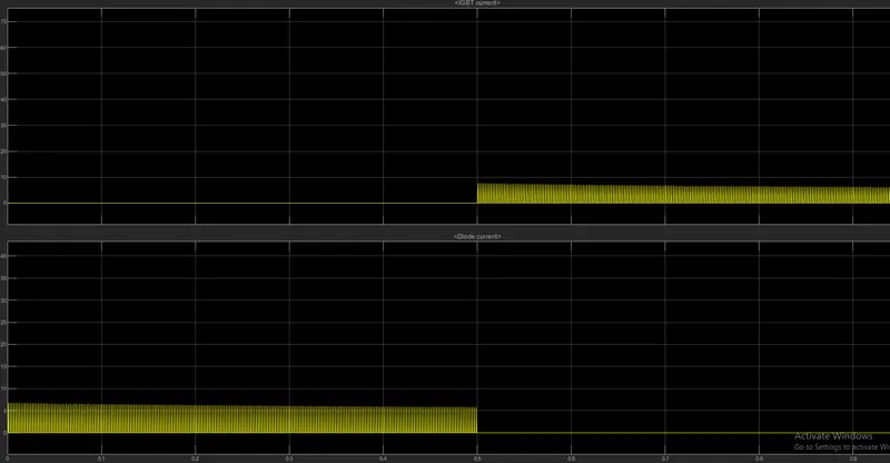
>In the current graph, the amount of circuit is acted as shown of graph result and the graph showing represented of IGBT current and diode current travel passed through in Quadrant Q3 and DidodeD3
>Where Q3 indicates of Igbt current
> D-shows od diode current
>When the Q3 is off then it alternative starting flow of diode current so that it on stage
>At a point of current flow in diode as 0.5 up to and remaining to go with contact went the IGBT current is active so that after 0.5 times reached the crossed of point The IGBT current is activated
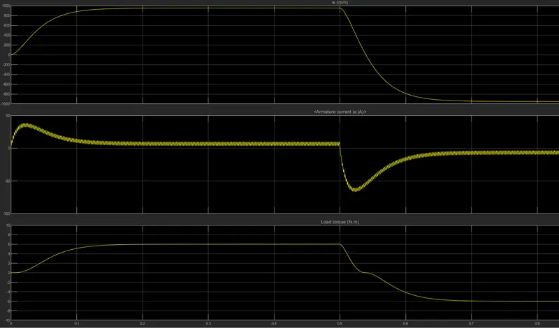
>Armerature current and load current
>The speed and armature current is indicated by the motor and load torque
>In this result graph observation when the speed is increasing in a short time period then that the alternative armature current is positive so were as the load torque is also forward direction
>As per sudden changes flow current is acted then its form the current armature current is changed at a positive and negative terminal
>At a starting point small various of increasing in armature current and after a crossed the 0.5 then its gradually flow down suddenly and load torque also gradually decreasing up to constant level
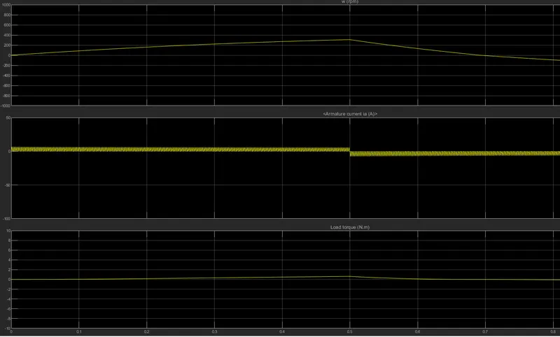
>BY changing pulse generator as in the input value :
>OUTPUT:
>Armerature current and load current
C. Refer to the help section of ‘The Four-Quadrant Chopper DC Drive (DC7) block’. Compare it with the H-bridge
Description
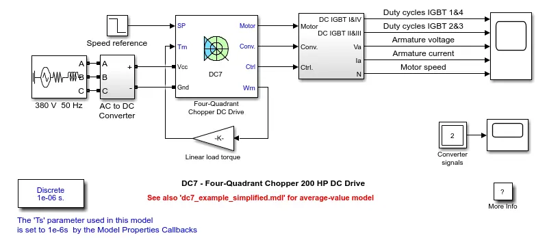
The 200 HP DC motor is separately excited with a constant 150 V DC field voltage source. The armature voltage is provided by an IGBT converter controlled by two PI regulators. The converter is fed by a 515 V DC bus obtained by rectification of a 380 V AC 50 Hz voltage source. In order to limit the DC bus voltage during dynamic braking mode, a braking chopper has been added between the diode rectifier and the DC7 block.
The first regulator is a speed regulator, followed by a current regulator. The speed regulator outputs the armature current reference (in p.u.) used by the current controller in order to obtain the electromagnetic torque needed to reach the desired speed. The speed reference change rate follows acceleration and deceleration ramps in order to avoid sudden reference changes that could cause armature over-current and destabilize the system. The current regulator controls the armature current by computing the appropriate duty ratios of the 5 kHz pulses of the four IGBT devices (Pulse Width Modulation). For proper system behaviour, the instantaneous pulse values of IGBT devices 1 and 4 are opposite to those of IGBT devices 2 and 3. This generates the average armature voltage needed to obtain the desired armature current. In order to limit the amplitude of the current oscillations, a smoothing inductance is placed in series with the armature circuit.
Simulation
Before starting the simulation, set the initial bus voltage to 515 V via the GUI block ('Initial States Setting' button and 'Cbus' variable).
Start the simulation. You can observe the motor armature voltage and current, the four IGBT pulses and the motor speed on the scope. The current and speed references are also shown.
The motor is coupled to a linear load, which means that the mechanical torque of the load is proportional to the speed.
The speed reference is set at 500 rpm at t = 0 s. Observe that the motor speed follows the reference ramp accurately (+400 rpm/s) and reaches steady state around t = 1.3 s.
The armature current follows the current reference very well, with fast response time and small ripples. Notice that the current ripple frequency is 5 kHz.
At t = 2 s, speed reference drops to -1184 rpm. The current reference decreases to reduce the electromagnetic torque and causes the motor to decelerate with the help of the load torque.
At t = 2.2 s, the current reverses in order to produce a braking electromagnetic torque (dynamic braking mode). This causes the DC bus voltage to increase.
At t = 3.25 s, the motor reaches 0 rpm and the load torque reverses and becomes negative. The negative current now produces an accelerating electromagnetic torque to allow the motor to follow the negative speed ramp (-400 rpm/s). At t = 6.3 s, the speed reaches -1184 rpm and stabilizes around its reference.
Notes
1) The power system has been discretized with a 1 us time step. The speed and current controllers use a 100 us and 20 us sampling time respectively in order to simulate a microcontroller control device.
2) In order to reduce the number of points stored in the scope memory, a decimation factor of 25 is used. Some transitions may thus not appear on the scope. To view detailed simulation results, reduce the decimation factor to 1.
3) A simplified version of the model using an average-value converter can be used by selecting 'Average' in the 'Model detail level' menu of the graphical user-interface. The time step can then be increased up to the smallest control system sample time value. This can be done by typing 'Ts = 20e-6' in the workspace in the case of this example. See also dc7_example_simplified model.
Four Quadrant Operation of DC motor means that the machine operates in four quadrants. They are forward motoring, Forward braking, reverse motoring and reverse braking.
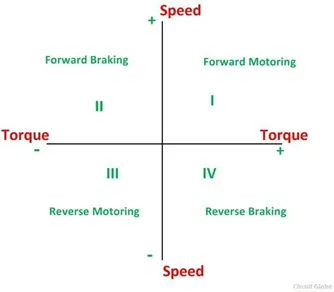
QUADRANT - I
- When the motor draws power from supply, the voltage and current are in same direction.
- Now the motor is said to be in motoring operation, its operation corresponds to the 1st quadrant.
- In the 1st Quadrant power developed in positive and machine is working as motor supplying mechanical energy. The 1st quadrant operation is called Forward motoring.
QUADRANT - II
- If there is a possibility of reversing the current direction keeping the voltage polarity same, the motor is said to be operating in 2nd quadrant.
- This happens when regenerative braking is applied to motor.
- During regenerative braking operation, reverse power flow will happen i.e power will be feedback to supply system. @nd quadrant operation is known as braking.
- In this quadrant the direction of rotation is positive and the torque is negative and thus the machine operates as a generator developing a negative torque that opposes the motion.
- The kinematic energy of the rotating part is available as electric energy which may be supplied back to mains. In dynamic braking energy may be supplied back to mains. In dynamic braking energy is dissipated in the resistance.
QUADRANT - III
- If the voltage polarity and load current are reversed simultaneously, the motor operation will be in the opposite direction, but the power will be consumed by the load.
- The operation is corresponding the 3rd Quadrant and even it is said to be in motoring operation. The 3rd quadrant operation is known as reverse motoring.
- The motor works, in the reverse direction. Both the speed and torque have negative values while the power is positive.
QUADRANT - IV
- If the voltage polarity is reversed maintain the current direction source to load the power is reversed and the operation corresponding to 4th quadrant.
- Now the motor is said to be in reverse Regenerative operation.
- In the 4th quadrant, the torque is positive and speed is negative. This quadrant corresponds to braking in the reverse regenerative braking mode.
BJT H - Bridge Drive |
Four quadrant chopper drive |
|
It is used for changing the direction of the Motor. Regenerative Braking cannot be available. The source is of fixed DC supply. The armature current shoots up during the phase transition. Less control of the Vehicle Signals are continuous |
Here the motor can be operated in 4 different modes. Regenerative braking can be achieved. The source is an AC supply which can be rectified to DC varying supply. The armature current doesn't shoot up to the value of BJT H-bridge but for low voltage value, it's negligible. Better control of the vehicle Signals are not continuous and they are discrete. |
2. Develop a 2-quadrant chopper using simulink & explain the working of the same with the relevant results. (Refer to article - Multiquadrant operation of motor )
SIMULINK MODEL
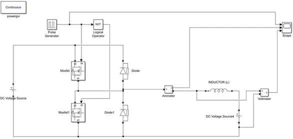
>Construction blocks:
>Mosfet
>Diodes
>Dc voltage sources
>Inductor
>pulse generator
>voltmeter
>Power GUI
>Explanation:
>The two-quadrant chopper Dc drive bock represented by dc-quadrant
>By using the two-quadrant drive, the benefits of its, Comparing and implementation logical operators is simplicity and it that can operate in two quadrant
>Were using of highly frequency switch in DC-Dc convertor as per a lower armature current supplied is obtained
>Therefore, all two-quadrant dc drives are reversible and regenerative operation
>RESULT SCOPE: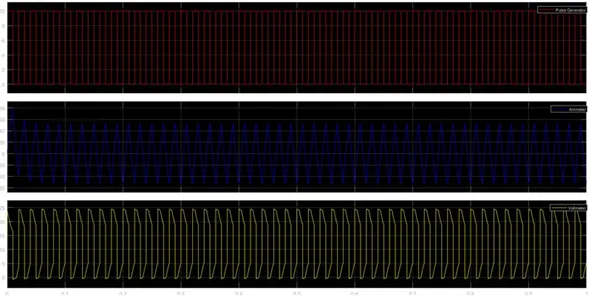
3. Explain in a brief about operation of BLDC motor.
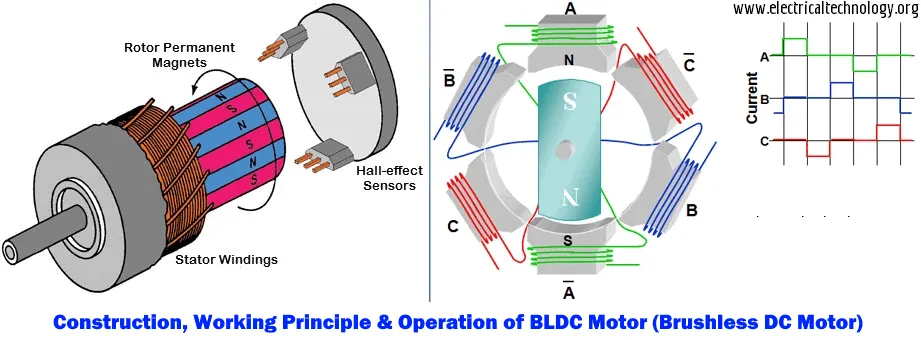
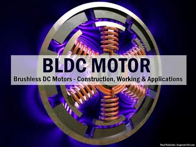
Construction, Working & Applications of BLDC (Brushless DC Motor)
- Brushless DC motors (BLDC) have been a much focused area for numerous motor manufacturers as these motors are increasingly the preferred choice in many applications, especially in the field of motor control technology. BLDC motors are superior to brushed DC motors in many ways, such as ability to operate at high speeds, high efficiency, and better heat dissipation.
- They are an indispensable part of modern drive technology, most commonly employed for actuating drives, machine tools, electric propulsion, robotics, computer peripherals and also for electrical power generation. With the development of sensorless technology besides digital control, these motors become so effective in terms of total system cost, size and reliability.
What is a Brushless DC motor (BLDC)?
- A brushless DC motor (known as BLDC) is a permanent magnet synchronous electric motor which is driven by direct current (DC) electricity and it accomplishes electronically controlled commutation system (commutation is the process of producing rotational torque in the motor by changing phase currents through it at appropriate times) instead of a mechanically commutation system. BLDC motors are also referred as trapezoidal permanent magnet motors.
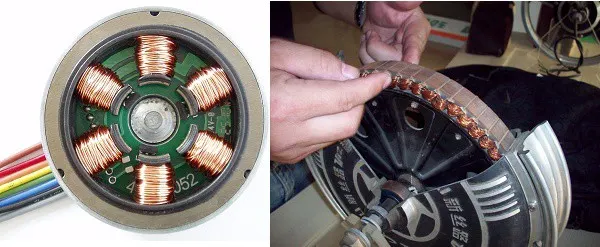
- Unlike conventional brushed type DC motor, wherein the brushes make the mechanical contact with commutator on the rotor so as to form an electric path between a DC electric source and rotor armature windings, BLDC motor employs electrical commutation with permanent magnet rotor and a stator with a sequence of coils. In this motor, permanent magnet (or field poles) rotates and current carrying conductors are fixed.
- This electronic commutation arrangement eliminates the commutator arrangement and brushes in a DC motor and hence more reliable and less noisy operation is achieved. Due to the absence of brushes BLDC motors are capable to run at high speeds. The efficiency of BLDC motors is typically 85 to 90 percent, whereas as brushed type DC motors are 75 to 80 percent efficient. There are wide varieties of BLDC motors available ranging from small power range to fractional horsepower, integral horsepower and large power ranges.
- The armature coils are switched electronically by transistors or at the correct rotor position in such a way that armature field is in space quadrature with the rotor field poles. Hence the force acting on the rotor causes it to rotate. Hall sensors or rotary encoders are most commonly used to sense the position of the rotor and are positioned around the stator. The rotor position feedback from the sensor helps to determine when to switch the armature current.
Advantages of BLDC Motor
BLDC motor has several advantages over conventional DC motors and some of these are
- It has no mechanical commutator and associated problems
- High efficiency due to the use of permanent magnet rotor
- High speed of operation even in loaded and unloaded conditions due to the absence of brushes that limits the speed
- Smaller motor geometry and lighter in weight than both brushed type DC and induction AC motors
- Long life as no inspection and maintenance is required for commutator system
- Higher dynamic response due to low inertia and carrying windings in the stator
- Less electromagnetic interference
- Quite operation (or low noise) due to absence of brushes
Disadvantages of Brushless Motor
- These motors are costly
- Electronic controller required control this motor is expensive
- Not much availability of many integrated electronic control solutions, especially for tiny BLDC motors
- Requires complex drive circuitry
- Need of additional sensors
Applications of Brushless DC Motors (BLDC)
Brushless DC Motors (BLDC) are used for a wide variety of application requirements such as varying loads, constant loads and positioning applications in the fields of industrial control, automotive, aviation, automation systems, health care equipments, etc. Some specific applications of BLDC motors are
- Computer hard drives and DVD/CD players
- Electric vehicles, hybrid vehicles, and electric bicycles
- Industrial robots, CNC machine tools, and simple belt driven systems
- Washing machines, compressors and dryers
- Fans, pumps and blowers
Working Principle and Operation of BLDC Motor
- BLDC motor works on the principle similar to that of a conventional DC motor, i.e., the Lorentz force law which states that whenever a current carrying conductor placed in a magnetic field it experiences a force. As a consequence of reaction force, the magnet will experience an equal and opposite force. In case BLDC motor, the current carrying conductor is stationary while the permanent magnet moves.
-
When the stator coils are electrically switched by a supply source, it becomes electromagnet and starts producing the uniform field in the air gap. Though the source of supply is DC, switching makes to generate an AC voltage waveform with trapezoidal shape. Due to the force of interaction between electromagnet stator and permanent magnet rotor, the rotor continues to rotate.
-
Consider the figure below in which motor stator is excited based on different switching states. With the switching of windings as High and Low signals, corresponding winding energized as North and South poles. The permanent magnet rotor with North and South poles align with stator poles causing motor to rotate.
-
Observe that motor produces torque because of the development of attraction forces (when North-South or South-North alignment) and repulsion forces (when North-North or South-South alignment). By this way motor moves in a clockwise direction.