Final Project: Design of an Electric Vehicle
AIM: Designing of an Electric Vehicle by using o Matlab/Simulink, by choosing suitable blocks from the powertrain block set
Theory:
EV design – introduction
Vehicle design is a very complex domain since it involves a lot of attributes, like: interior space, dynamic performance, active and passive safety, connectivity, etc.. The same principles apply to either electric vehicles or conventional vehicles (with internal combustion engines) design.
In a series of articles we are going to focus on the high level design of an electric vehicle drive unit and battery pack. The same calculation methods can be applied whether we design an electric vehicle from scratch or if we do a conversion from a conventional vehicle.
The current article is an introduction, the full content being:
- EV design – introduction
- EV design – energy consumption
- EV design – battery
- EV design – electric motors
- EV design – mode management
- EV design – vehicle systems and components
- EV design – simulation model
- EV design – simulation results and evaluation
MODEL:
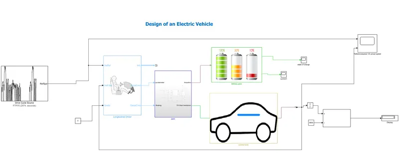
>Basic component to build:
Dc-motor
Battery
Vehicle body
Longitudinal driver
H-bridge
Drive cycle
>Part-1(vehicle body)Inside subsystem
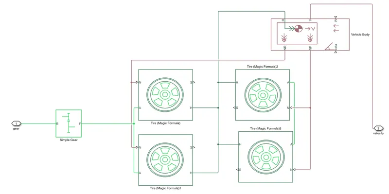
>Inside the vehicle body structure
>Firstly Tier-two rear axle and two front axle
>next we have to connect the power of the motor or shaft of the motor through the transmission system to the rear axle
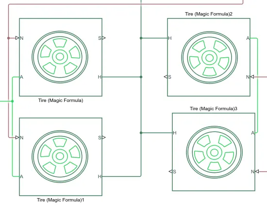
>There are four ports terminals which are :
H-hub
S-Tier slip
The N-normal force applied to the tier
A-Acceleration connection
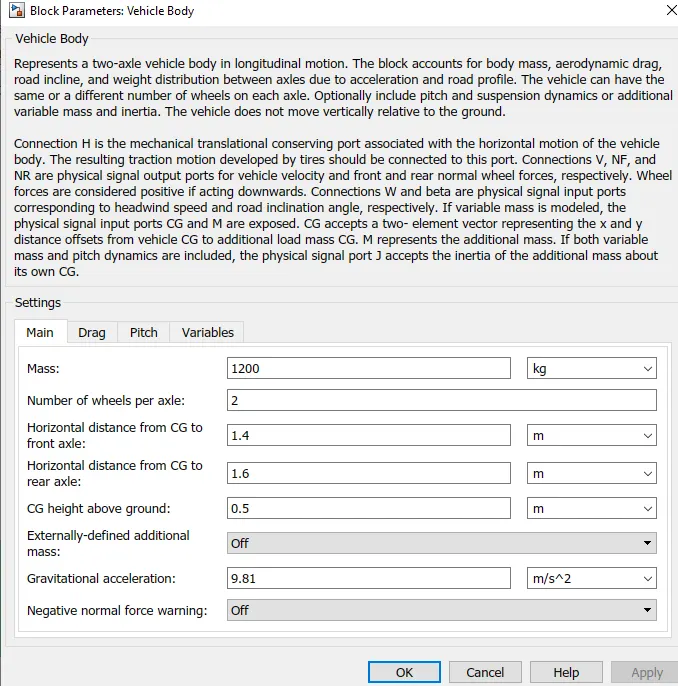
2.Vehicle body:
>Then we connected the tier with tier with vehicle body vehicle relative parameters
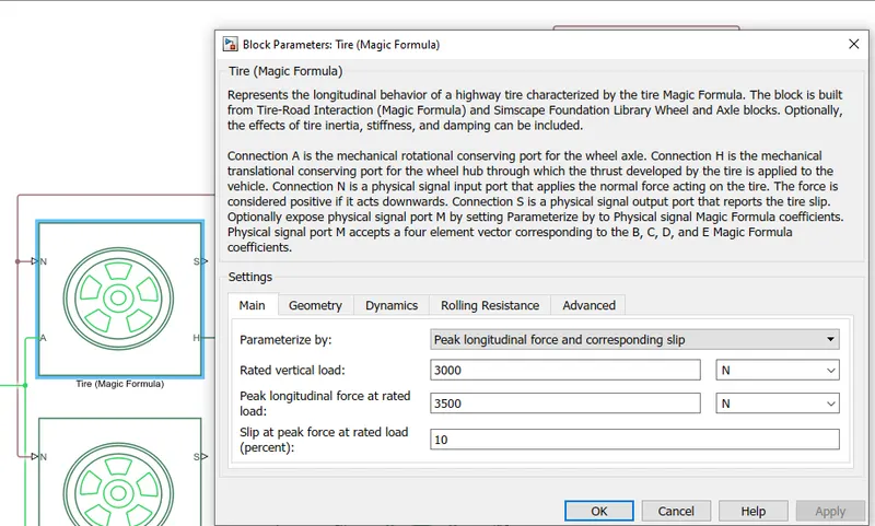
>Based on tire magic formula we should taken of any condition
>In this I did not doing any applying on the slip so that I kept of const part
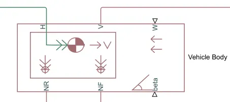
>If beta angle we can connect when the vehicle moving at some inclination angle
>And v- vehicle velocity part input
>W-wind velocity-constant
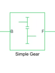
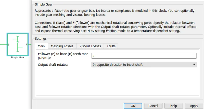
3. GEAR SYSTEM:Simple gear
>After than the rear axle tire is connected with simple ger system and output gear system part is connected to rear axle tire and input gear single is connected with shaft of the motor
>Nr-normal force to rear shaft(nr)
4.MOTOR:
There are several of motor like dc,brushless motor,bdlc motor,simple motor
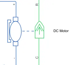
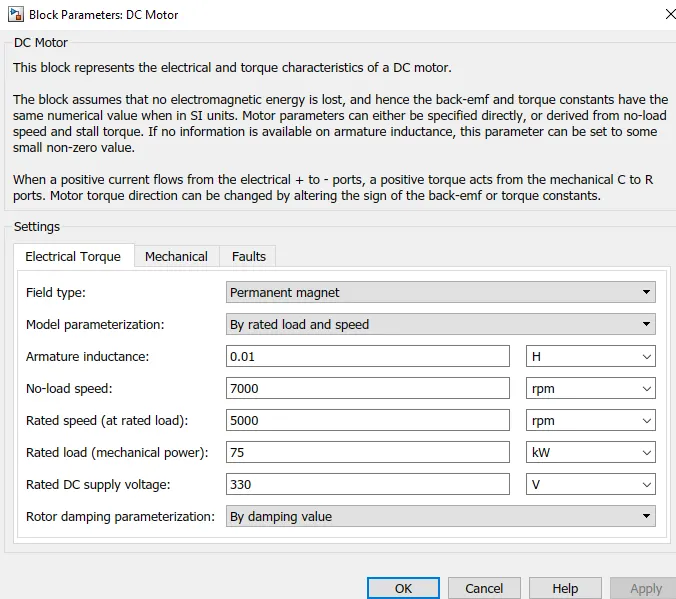
Dc-motor-were combined of both mechanical and electrical
R-rotator
C-casing
Green-mechanical references
Blue - electrical references
>The motor is connecting to a simple gearbox input rotator shaft
>casing is a fixed point so that constant fixed connected to rotational mechanical references
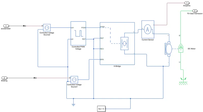
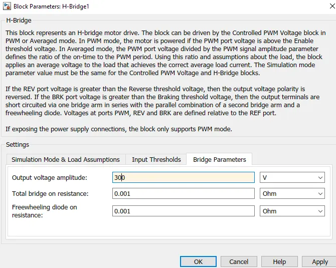
>After that we need to control of dc-motor so that it should be controlled by dc-dc motor converter and were used of H-bridge
>If we connect directly to battery dc-motor we will lose any control of the vehicle
5.H-bridge:
>Combination of four switches and its consists of one of positive terminal port and another negative terminal of the battery and in that inside two terminal we have to connets to motor(+,+)(-ve,-ve)
>we have inputs of H-bridge are:
>PWM
>RF
>REV
>BRK
>And these are four control inputs and back if two power outputs and(+ve,-ve) are power inputs
>So I am using a simple dc motor at my first level there are different motors also available
>According to vehicle speed gear ratio we have to choose rate speed of the motor
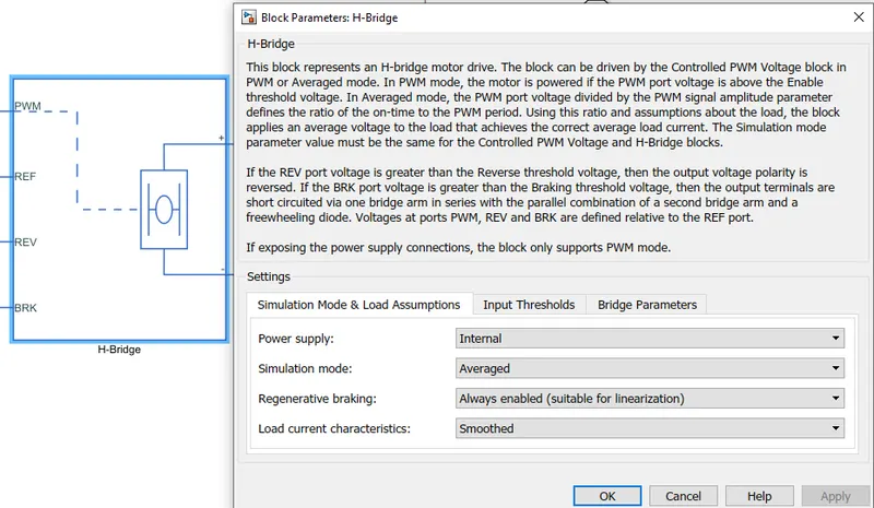
>By there are two options in H-bridge as (a)Internal (b) external
>By choosing internal we cannot connect with battery by this h-bridge its take power its own itself dc_sources
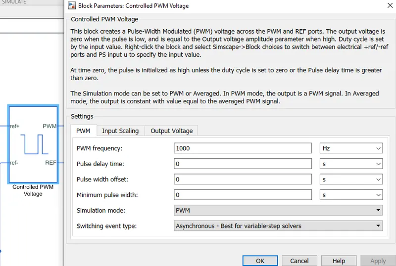
>To control PWM so that we have to connect the controlled PWM voltage this block actually generates of pulse and based on this pulse from fixed point voltage variable output voltage available to the motor and the motor speed and motor torque will be charges
>Rev,BRK are not acting any application on it so that I connected with the ground current which as electrical references
>By ref+ should be applied of controlled inputs
>Controlled voltage source containing to controller inputs
>Another controlled source is connecting with brake that of regenerative braking so we want to use of rengerative braking now
>Regenative braking is nothing but whenever vehicle speed is reduced the power can flow back to their battery and the battery will charge
>If i applied acceleration signal at PWM parts of H-bridge and this reduced the speed of the motor and it will apply of regenerative brake
>Controlled PMW voltage its uses that the from a fixed battery voltage the variable output will available in motor or motor shaft and torque also changes
H-bridge:
>controlled PWM voltage sources
DC MOTOR:
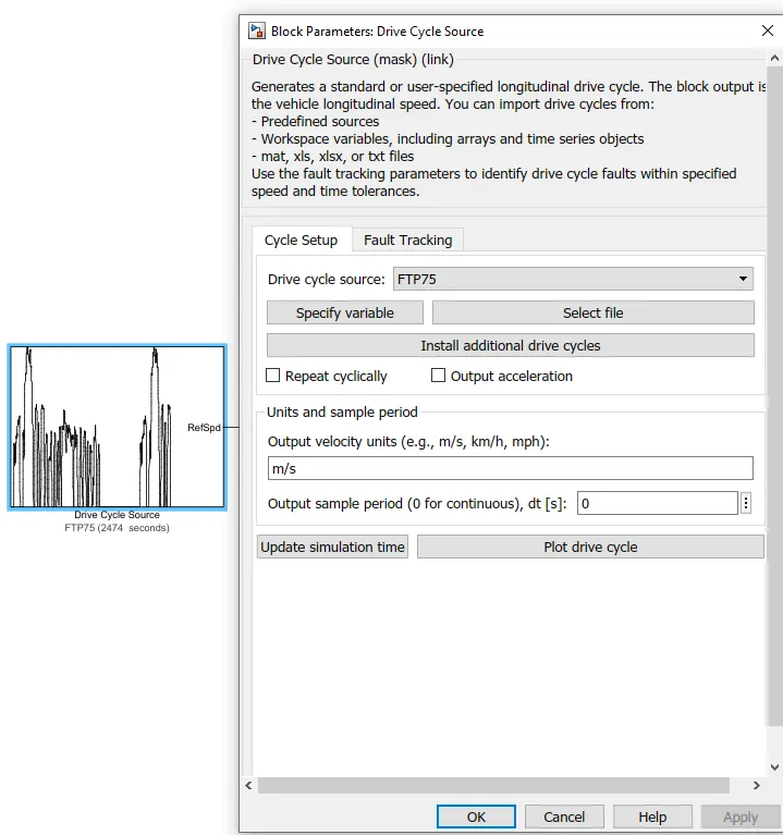
6.Drive cycle:
There are no of standard drive by using cycle is predefined the input values (speed vs time)
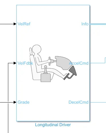
>By converting speed data into acceleration command so that we required controller then i am using as driver so that longitudinal driver is placed.so that the driver const following the vehicle references speed and compared with vehicle speed coming from the vehicle model
>In final the given speed reference sped is greater than actual speed then its means of the driver isgoing to pressing accelerator
>If actual speed is more than references speed then the driver is applied to brakes
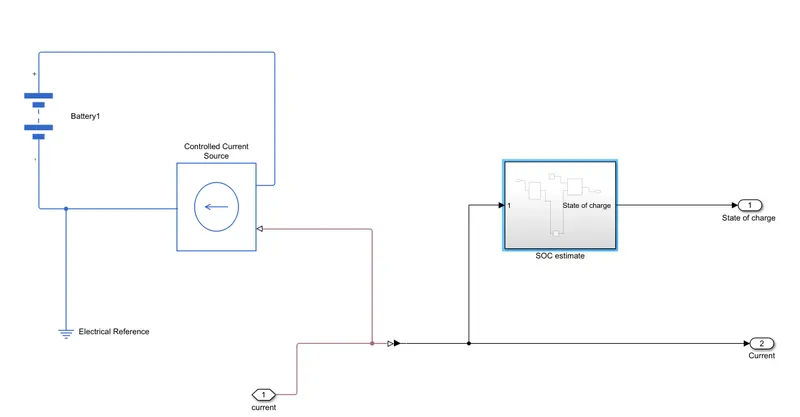
7.Battery
>Accordibg to discharge which are taken from current dcmotor i am using simple battery so that i am using current sensor
>Were using of interger by this we can converts speed in Km/h and distance in Km
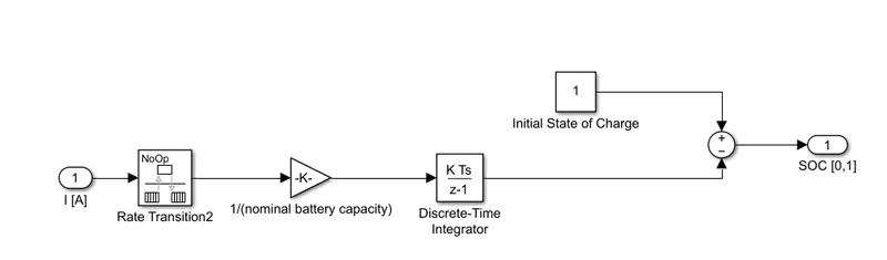
SOC ESTIMATE:
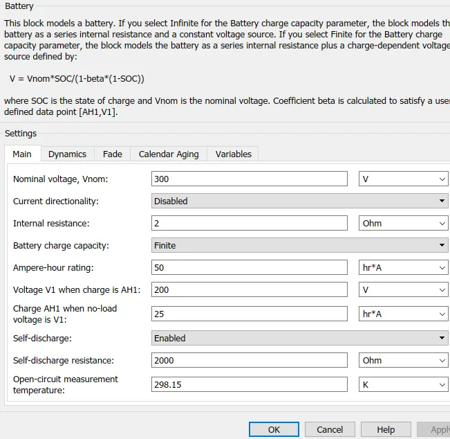
Battery parameters:
>Output result:
Soc
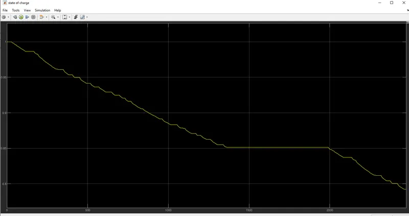
>Hence see that the battery is slowly discharging as starts from 1 and while running of the vehicle the battery is consuming the battery power so that it will discharging and were at between 1300 to 2000sec the soc is constantly because the vehicle is stopped or any no load applied force on vehicle
>Current:
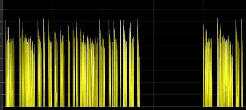
>since the current is rise the frequency high to low voltage frequency of current and in the sudden gap at 1300 to 2000 so that it while the vehicle is under constant position without any applied or start position
Speed:
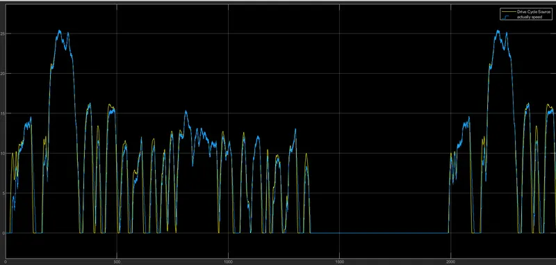
>As per speed requirement the see in above the drive cycle vs and actual speed travels here approximately the vehicle speed is traveling with references speed while starting position some were of changes and remaining the speed is traveling with references speed and were speed also at the constant drop at 1300 to 2000 while means the vehicle is a constant position only
>Distances traveled:
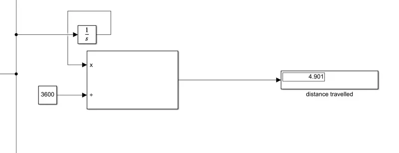
>The distance traveled at 4.901 km and run time of drive cycle is 2474 sec which is given as input speed vs time drive cycle standard value
Conclusion:
>hence the vehicle traveling at a distance of 4.9 km and which depends on the input given as drive cycle standard FTP cycle and run of simulation 2474sec
>The battery is having 300v and which is nominal voltage and ampere-hour is 50 by which were the soc charge calculated
>While dc motor depends of run on wheel rear axle of the vehicle body when the car is no load the speed is 7000 rpm and when the load in the vehicle 5000rpm and were rated dc supply voltage is 330v