Week - 4
AIM :
- Implement control logic of a “washing machine” using Stateflow as per given sequence:
- If the power supply is available, the system gets activated
- If the Water supply is not available, stop the process & indicate through LED
- Soaking time should be 200s followed by Washing time of 100s.
- Then rinsing happens for the next 20s & dryer runs for 50s
>Explanation :
- Washing machine is the machine used to wash the various types of clothes without applying any physical efforts. With washing machine you don't have to rub the clothes with hand or squeeze them to remove the water from them. The washing machine is also called as clothes washer or simply the washer
>PROCEDURE:
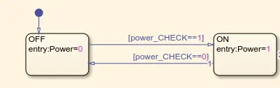
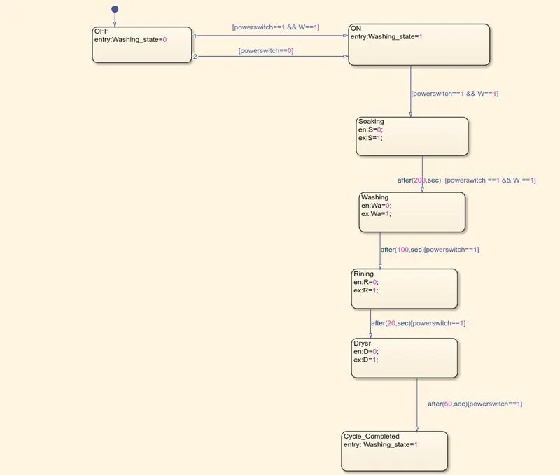
Step 1 :Creating physical state and now starting value at position as on/off as state 1 as off and state 2 on in this output washing_state=0(Its meaning washing power switch is off position)and another state 2 output washing_state=1(Its means power switch is on ),and statring position giving input to the model powerswitch==1 and powerswitch==0

Step 2 : After creatin on/off condition to washing state then connecting to the next state soaking input giving as powerswitch==1 because while the power is on its starts the function and output to the state entry soaking =1and exist = 0,the entry and exist reason beause its will run the model upto condition and its skip to next state block after it process to next state ,output to the state soaking 200sec its means to changing next state and soaking time taking 200sec at that state block
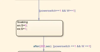
Step 3 : After 200sec soaking entring to washing position and the input at washing 100sec and output entryw=1 while on and ex:0 while off position
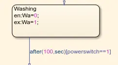
Step 4: After 100 sec of wash its passed to rinsing as happening at 20 sec
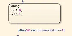
Step 5 :After 20sec rising is passing to Dryer at 50sec run and final state is connected cycle completed
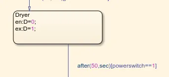
Step 6 After dryer at 50 sec to connected with end of cycle completed
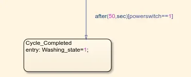
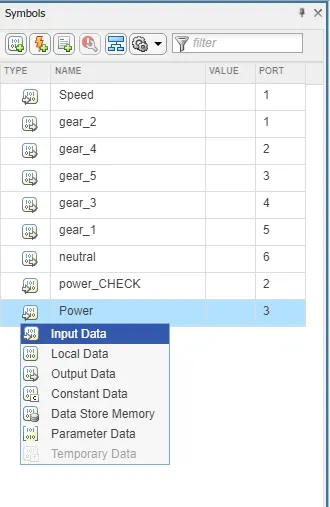
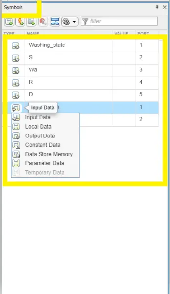
Step 7 After created of washing machine flowchart connected the data in the symbol panel and assign the data history separately to each block inputs and outputs mentioned to the names
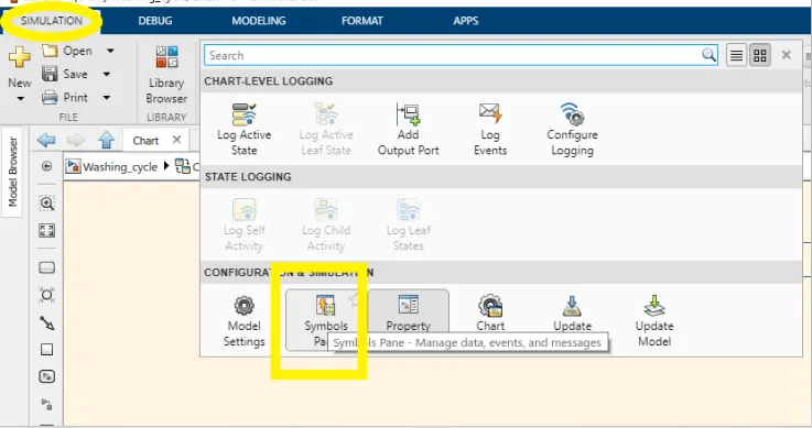
After clicking the symbol panel and its visible at side of window screen and change the values inputs and outputs to the model
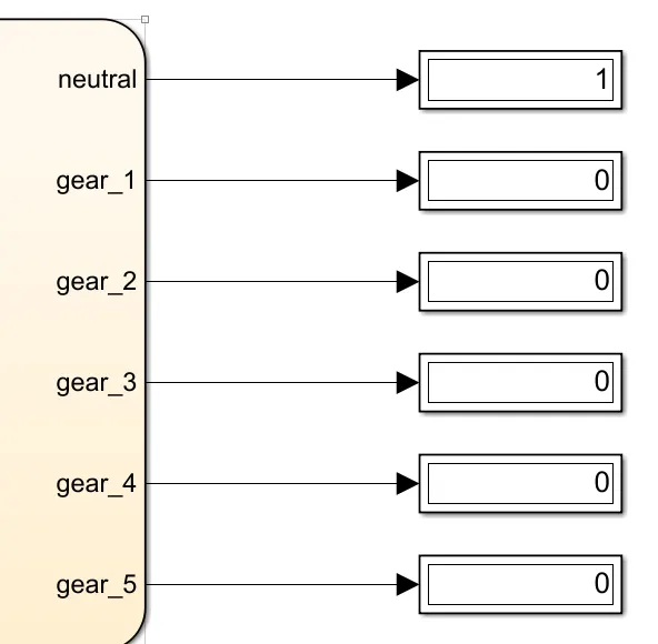
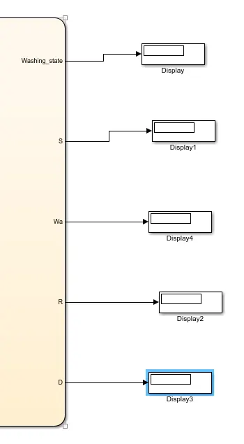
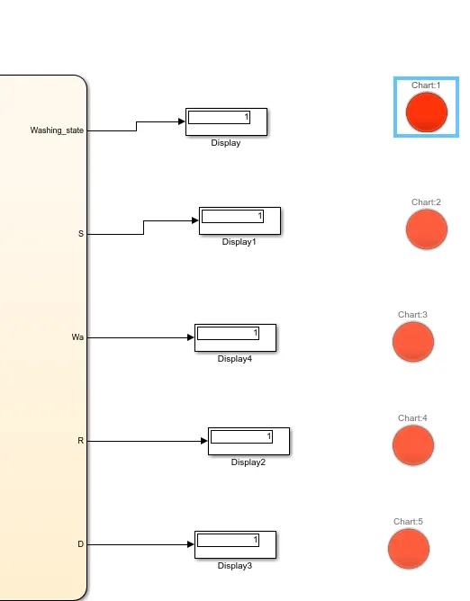
Step 8: After assigning the values in the symbol panel and connected with a display that is out of chart flow display which shows the result while the simulation is running whether its on/off
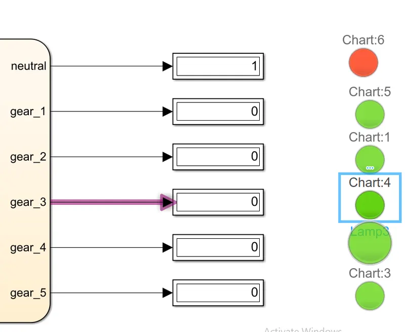
Step 9 : Connect the display to lamp,lamp is used from giving singal in colour output
>lamp is conneted done with diplay
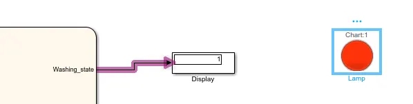
>Finally connected all display with lamp connection to see all signal whether there are in on/off
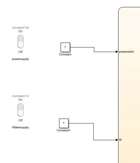
Step 10 : Input is given data power switch and water supply and on/off is connected separately to power switch and water supply with rockerswitch
Simulink model :
Simulink model in chart flow :
>Final running model Simulink :
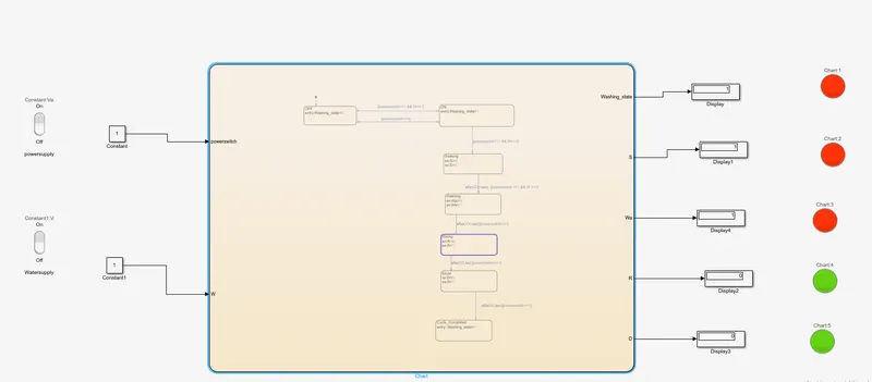
>Observation output :
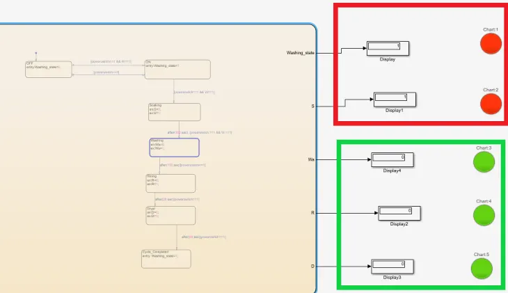
- As the power switch is on the power is passing flow in initial washing state with water supply to soaking state after 200 sec to washing state after 100sec to rising 20sec to dryer at 5sec in this process the whole function process flow is working on input power is on(1)condition, whether the switch is off there is no work process, and observer that after completed of whole cycle one after another completing state work process passing it will showing on display result automatically is going on/off(1/0)
Red colour is ON(1)
Green colour is OFF (0)
OBJECTIVE 2:
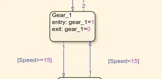
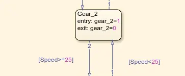
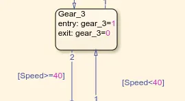
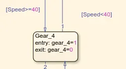
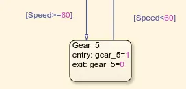
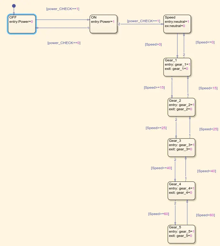
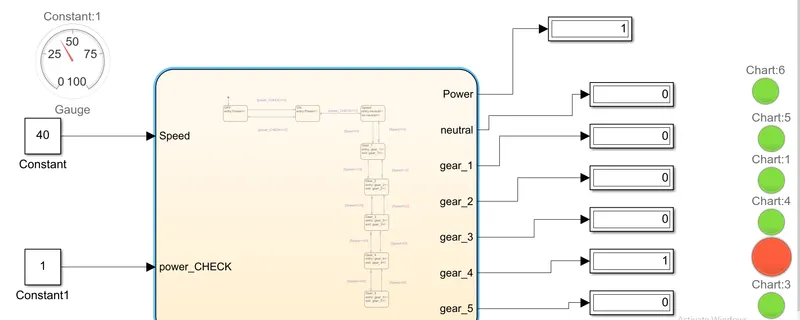
2. Make a Simulink chart for the “Gear shift” logic as per the below conditions:
Speed Range(kmph) Gear
0 to 15 1
16 to 25 2
26 to 40 3
41 to 60 4
Above 61 5
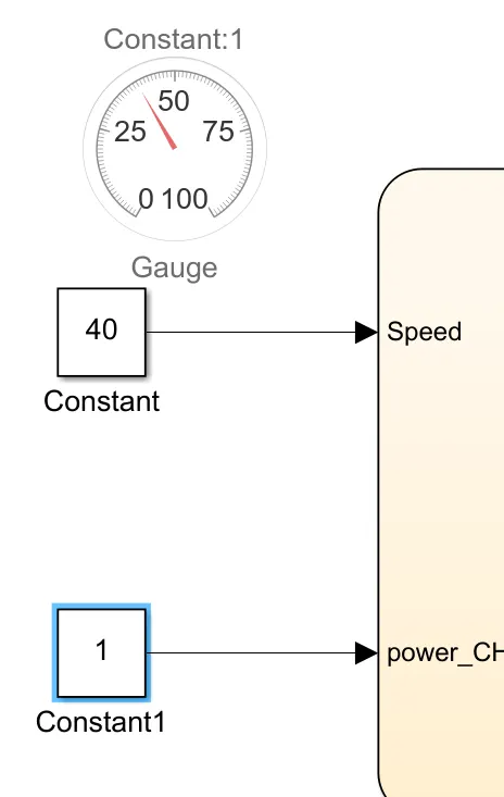
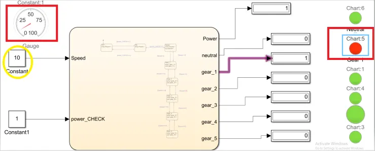
Give speed input while the simulation is running & display the gear number
Explanation :
What is the function of gear box:
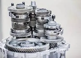
- The purpose of a gearbox is to increase or reduce speed. As a result, torque output will be the inverse of the speed function. If the enclosed drive is a speed reducer (speed output is less than speed input), the torque output will increase; if the drive increases speed, the torque output will decrease.