Assignment 7-Side Pole Crash Simulation Challenge
AIM : SIMULATION OF SIDE POLE CRASH CAR WHERE THE STRESS ARE WROKING ON IT
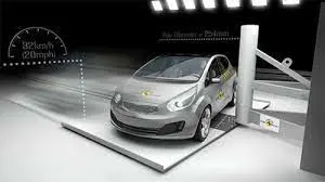
>Why we do need crash test : A crash test is a form of destructive testing usually performed in order to ensure safe design standards in crashworthiness and crash compatibility for various modes of transportation (see automobile safety) or related systems and components.
Crash testing helps develop safety systems and inform consumers, which takes some of that risk away. While smashing cars into walls or each other may seem wasteful, the data these tests yield is invaluable
>The side pole crash of car test needed : This is a severe test of a car's ability to protect the driver and passenger's heads in a side impact. As the loading on the car is so localized, deformation can be very high and the pole can penetrate deeply into the passenger compartment.
Question:
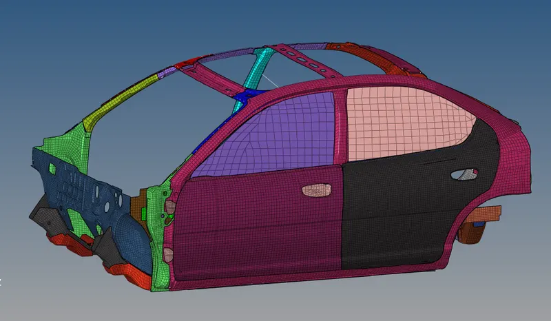
Neon side crash -BIW
- Check unit system and either follow [Mg mm s] or [Kg mm ms].
- Create appropriate interface ,friction 0.2 and recommended parameters.
- Make sure of no penetration and intersections.
- Create rigid wall with friction 0.1 as per referance model.
- Compare the model weight with the referance model and use added masses to reach target weight 700kg while getting CG about the required range.
- Initial velocity as shown in picture.
- Use model checker to ensure good quality.
- Timestep :0.5 to 0.1 microseconds.
- Run 80ms.
Output requests:
- Sectional force in the cross member.
- Intrusion at B pillar,hinge pillar and fuel tank region.Provide recommendation on what can help to reduce Fuel tank intrusion.
- Peak velocity of inner node of the door.
Objective 1 :
- Check unit system and either follow [Mg mm s] or [Kg mm ms].
>step 1 - Import the model as given radioss file 000.rad file
>step 2 - Now go with import model>cards as seen in the unit system
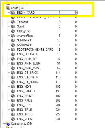
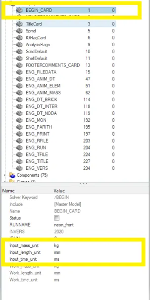
>Then now seen and any further changes in the units system as per given question I am following the units mass_unit=kg,length_unit=mm,time_length=ms
>Objective 2 :
- Create appropriate interface ,friction 0.2 and recommended parameters.
>Step 1 - Go with create>contact/interface/groups
>Step 2 - Now the changes of the recommended parameters then assigned it
>Step 3 - As per the given question the friction value is 0.2
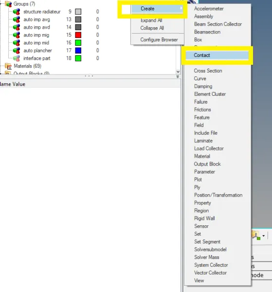
>Now click on new create an interface and makes changes parameters
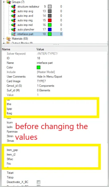
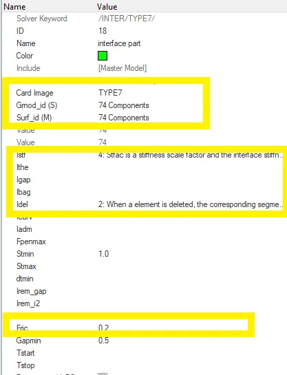
>As we go >Type 7>Igap=2,Inacti=6>Istf=4>Idel=2>Ifrm=2
>Objective 3 :
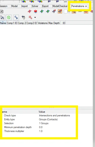
- Make sure of no penetration and intersections.
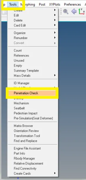
>step 1 : checking of penetration and intersection Tools>Penetration check
>Objective 4 :
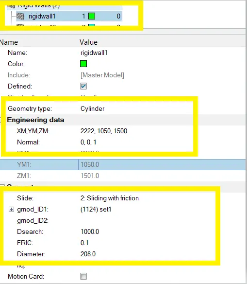
- Create rigid wall with friction 0.1
>Step 1 : Firstly we have a locate point node on the which position to create rigidwall
>Step2 : Then go with >create>rigidwall>Cyclinder
>Step3 : And the gives the axis of direction x,y,and z , I will place a node on a in front of the bumper plate and I locating x-axis so that I took of -1,y=o,z=o
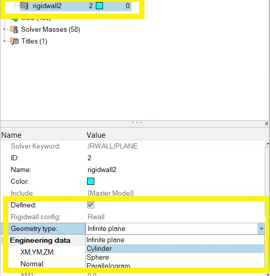
>AS the standarad value of fvmss the side pole diameter 208,214 as inforntal cash,216 roof crash part
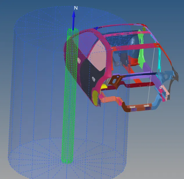
>Finally created of the rigid wall cylinder part
>Objective 5 : Compare the model weight with the reference model and use added masses to reach target weight 700kg while getting CG about the required range
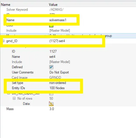
>Step 1 : Solver>create>ADMAS
>Step 2 : And now create a cog on the car part and select the node at a middle of cog
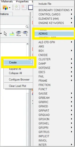
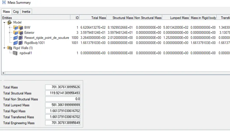
>While balancing the mass weight
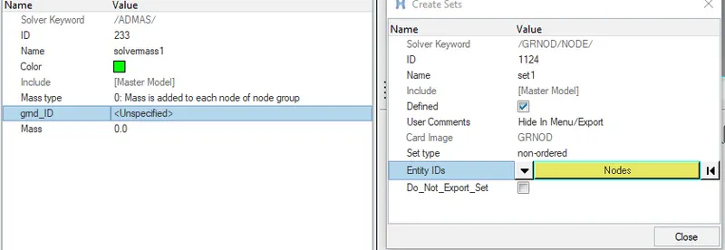
>Adding and minimizing the nodes to balancing the mass weight unstill required mass weight
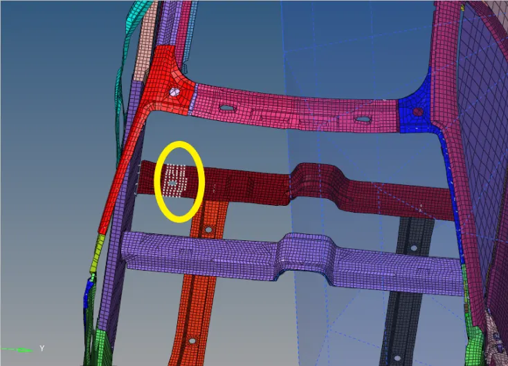
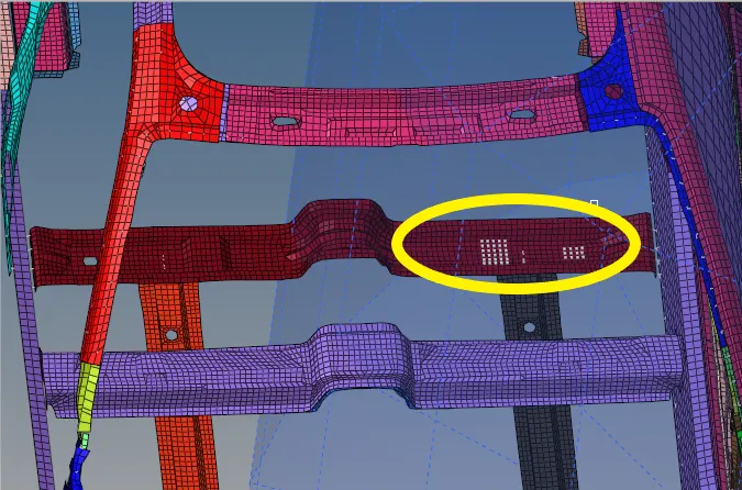
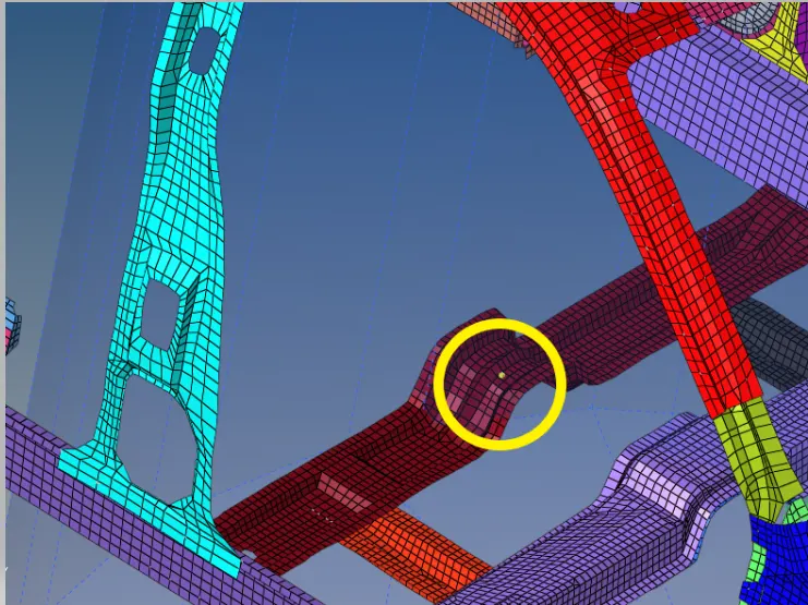
>Now finally created the cog point on the car part :
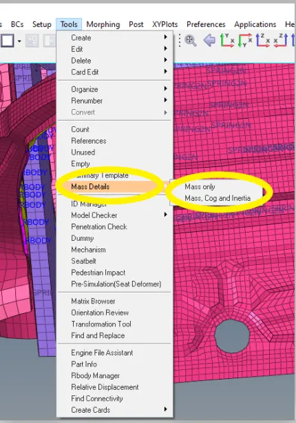
>To know how to check up the Cog :
>
>THe Total mass And cog :
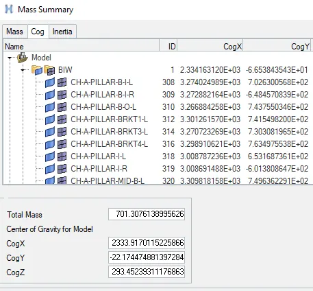
>THe Total mass :
>Objective 6 :
- Initial velocity 35 mph as given in the question
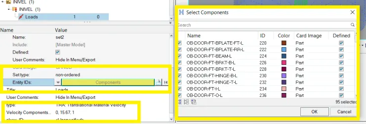
>Step 1 : Go with create>Bcs>IniVel
- Initial velocity 35 mph.
- Converting 35mph into ms
- 1mph = 0.447 ms
So, 35mph = 15.6464 ms
- The initial velocity (Vi) is the velocity of the object before acceleration causes a change. After accelerating for some amount of time, the new velocity is the final velocity (Vf).
- Initial velocity = [Final velocity - (acceleration×time)]
- vi = vf - at.
- vi = initial velocity (m/s).
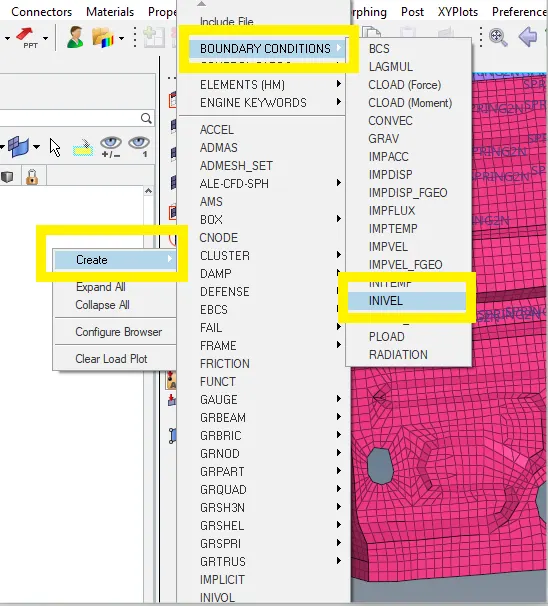
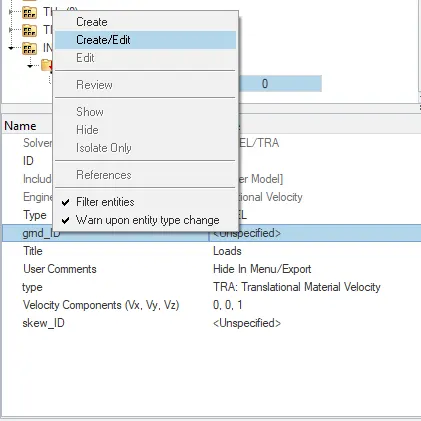
>At gmd_Id click on the right click
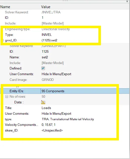
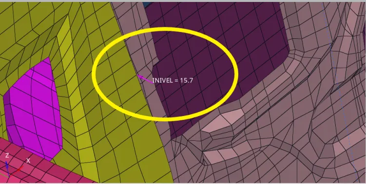
>Then we have to give the velocity to the whole component and as given velocity value 35mph and converting then 35mph to 15.67kph
>By nodes option selected all displayed nodes at that at collect all components nodes
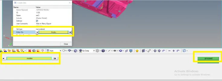
>Finally gives the proper value to assign the velocity
>Where the observer of global axis then I want gives in the direction of y-axis because side pole created by the side of car (which means x=0,y=15.67,z=0)
>Objective 7 :
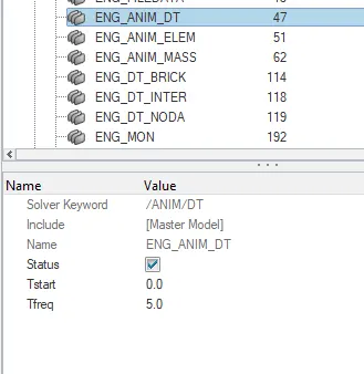
- Time-step :0.5 to 0.1 microseconds
>Step 1 : To check the Anim/Dt > time freq(0.5)
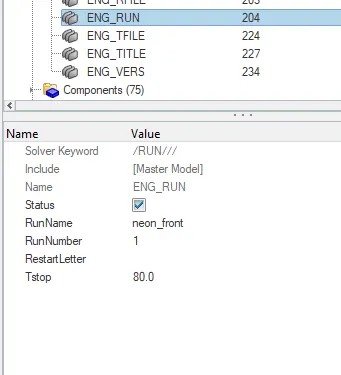
>Objective 8 : Engine run time (80)
>OUTPUT REQUEST :
>Objective 8:
- Sectional force in the cross member.
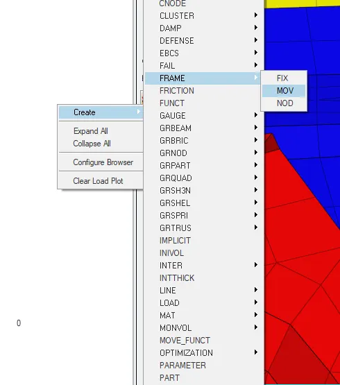
>Select>Slover>create>Frame>section
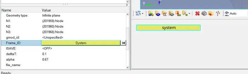
>Now create the Frame card in the solver browsers :
>Step 1 : Create>frame>mov
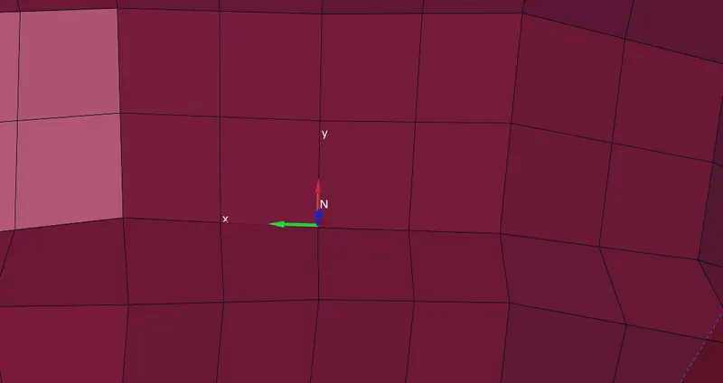
>Now givies the origin and x-axies ,xy-plane :

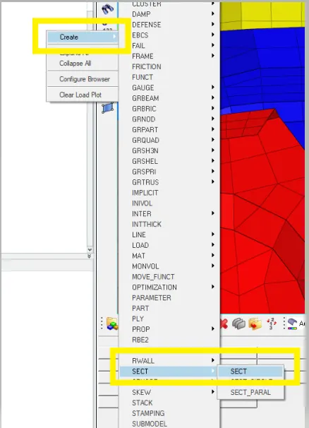
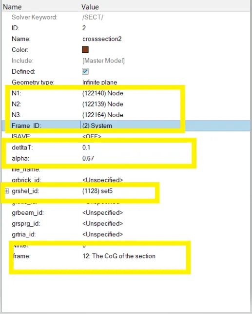
>Now creating the crosssection (section)
>Step 1 : slover>crete>sect
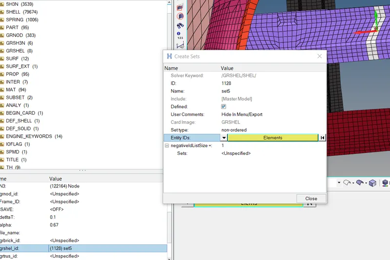
>Create grshel:
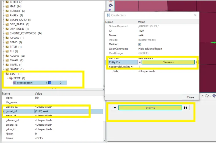
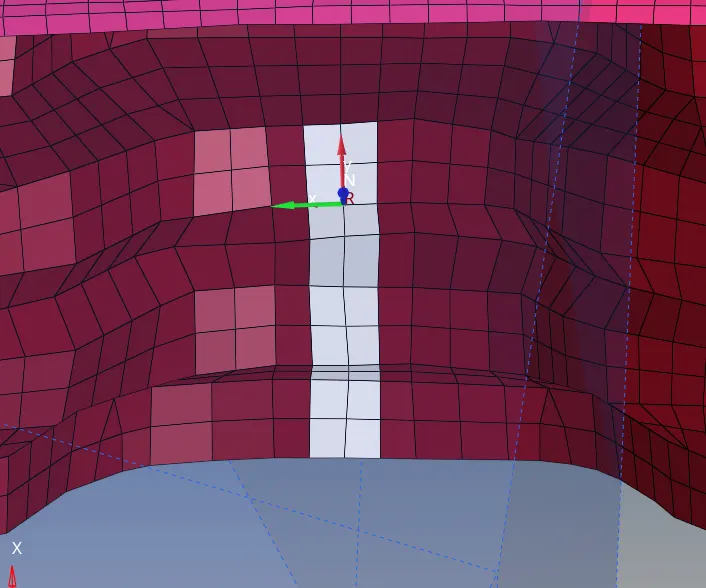
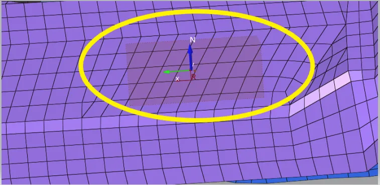
>Finally created of cross section on the cross member
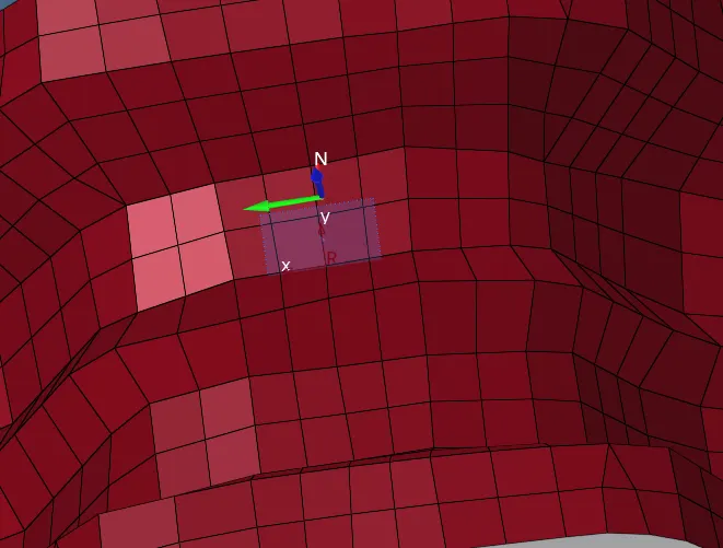
>Creating cross section another
>Givies the proper values in the parameters of cross-section :
>Objective 9 :
- Intrusion at B pillar,hinge pillar and fuel tank region
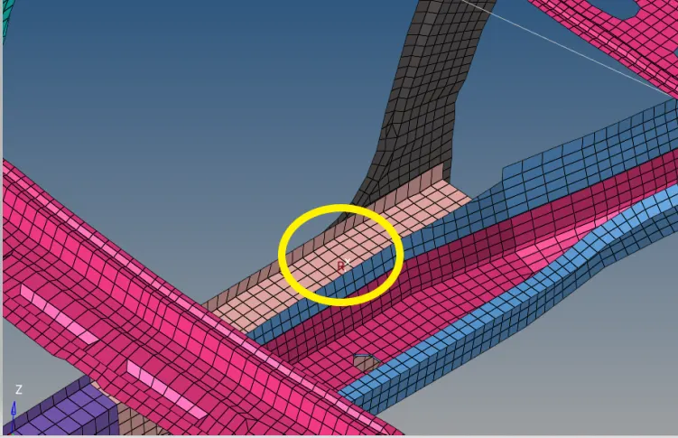
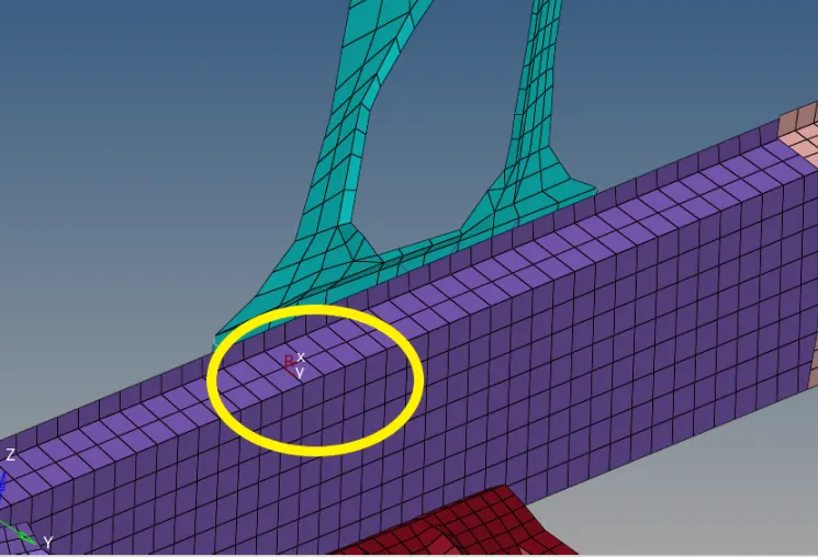
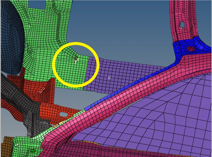
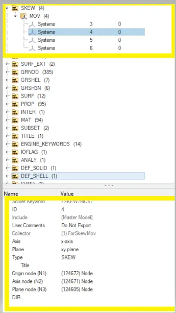
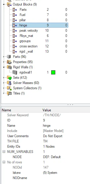
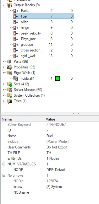
>Firstly create the skew(MOV) at all 3 pillar region and hinge region,and fuel tank region
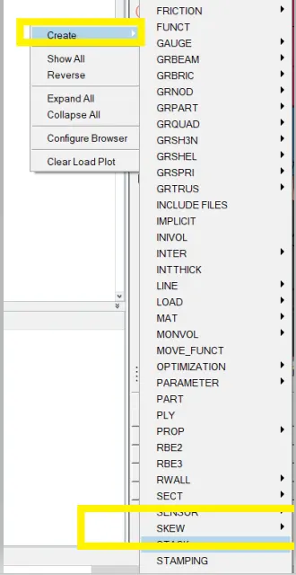
>Skew is created on the hinge :
>Skew is created on the pillar B
>Skew is created on the fuel tank region :
>Then I created skew and intrusion on hinge pillar,fuel tank,and B pillar
>Let see the output block on BPillar
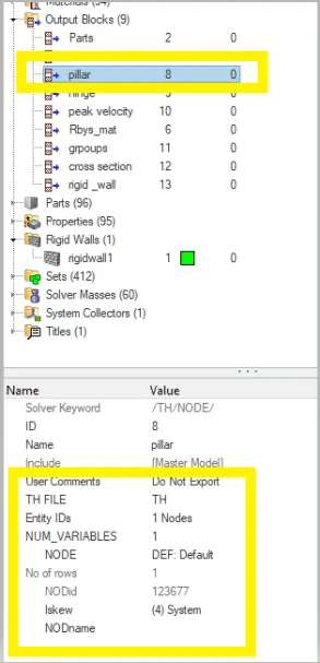
>Intrusion is created on the hinge region
>Creted intrusion on the fuel tank :
>Provide recommendations on what can help to reduce Fuel tank intrusion
>while impact side crash we can improve the quality of fuel tank or the bonded of extra heavy material supporting of fuel tank
>we can place at fuel tank by sides of rubber or shock observer materials
>Ojective 10 :
- Peak velocity of inner node of the door
>Then now creating peak velocity on the inner door
>Then create the skew at the inner door
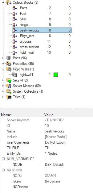
>And finally assign in the output block required parameters :
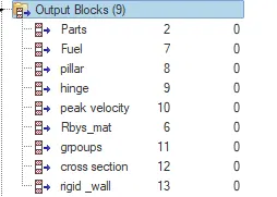
>Creating the interface part /group
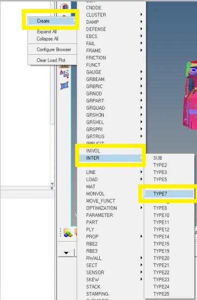
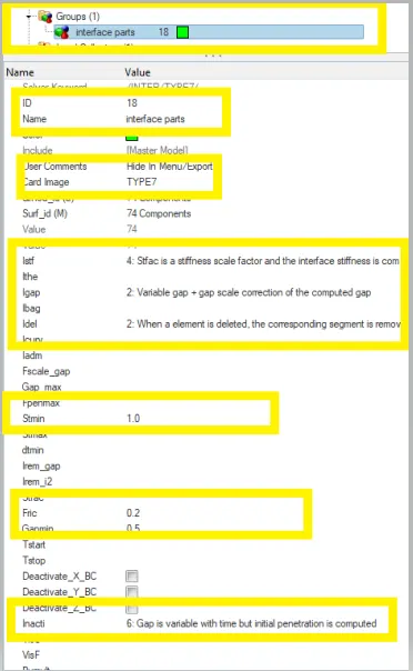
Type 7: Type 7 card is used to simulate all types of impact between a set of nodes and master surface. Main advantage of type 7 is stiffness is not constant and increases with the penetration preventing the node from going through the shell midsurface.
Istf 4: Stfac and stiffness is computed from both master and slave characteristics.
Igap 2: variable gap + gap scale correction of the computed gap.
Idel 2: When a 4-node shell, a 3-node shell or a solid element is deleted, the corresponding segment is removed from the master side of the interface. It is also removed in case of explicit deletion using Radioss Engine keyword /DEL in the Engine file. Additionally, non connected nodes are removed from the slave side of the interface.
Stmin 1: minimum stiffness (N/M)
GAPmin : Minimum gap for impact activation.
Inacti 6 : Gap is variable with time but initial penetration is computed .
Iform 2 : Stiffness (incremental) formulation.
SIMULATION OF THE SIDE POLE CRASH : Simulating and analysing car’s side pole crash.
STEP 1: Open Hyperworks in Radioss solver.
STEP 2: Import Solver desk Project_2_0000.rad file
STEP 3: Simulating model as it is.
*Analysis>Radioss>save as Project_2_0000.rad file>Checkbox include collectors>Write (-nt 4) in options>Click Radioss
STEP 4: Switch to Hyper view
STEP 5: Select local model and result Project_1.h3d file and T01 file
After simulation run
Check the Starter Output File for Errors:
- A starter Output file of .out format is generated after analysis.
- The Output file contains the data during simulation, such as Cycle, Timestep, Energies, and Errors.
- We have to check for energy and Mass error which means that the solver did not need to add mass onto the nodes to reduce the timestep to further avoid the Hourglass Error.
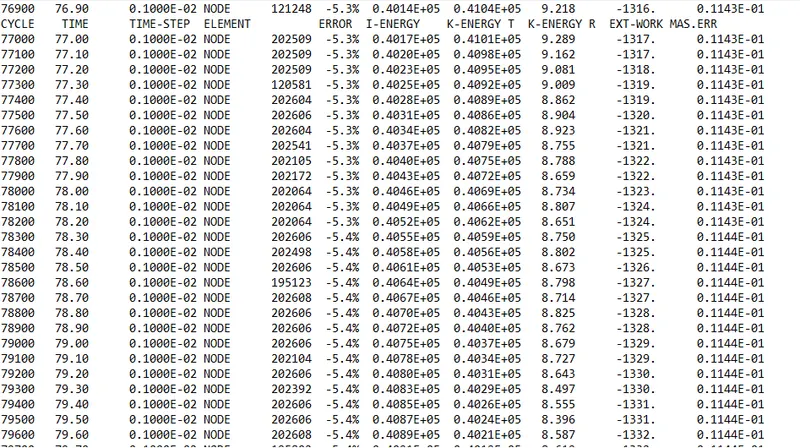
>The performing of simulation were of last cycle energy errors are obtainted of :
>Energy error = -5.4%
>Internal energy = 0.4087E+05
>Kinetic energy = 0.4021E+05
>External work =-1333
>Mass error = 0
>Total number of cycle =79601
OBSERVATION:
- The Energy Error is Negative.
- Mass error is zero which is acceptable
- We can conclude that there are no errors in the analysis.
Hypergraph 2D >> Data File >> FIRST_RUNT01 >> Apply
- A hypergraph is a data analysis and plotting tool that represents the FEA from the simulation in graphs with respect to the selected unit system.
- Selected T01 File (Time history file)

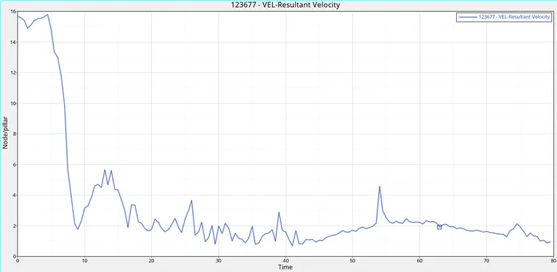
>PEAK VELOCITY :
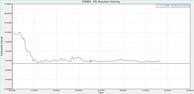
>As we all know that when the car hits the pole first impact will be the door and due to the deformation, the inner portion of the door might hit the passengers inside the car and lead to injuries. Hence it is important that the Peak velocity at the door region is to be calculated.
>As seeing the above of the graph the slight vibration because of the vibration occurring while during the crash of the Vechiel
>SECTIONAL FORCE :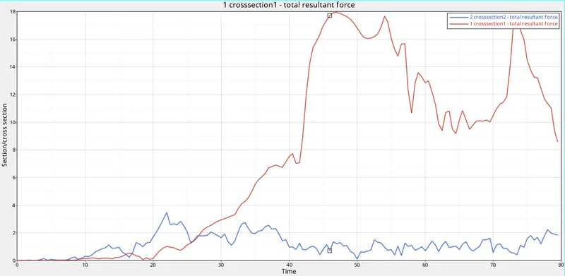
>we can see a rise in curves this is due to the force acting on the cross members, due to this force the cross members get bent, and the force passing through the cross members get reduced that why section 1 and section 2 will not drops its origin position after the crash
>AS see the graph and in the animation file cross-section 1 and cross-section 2
>FUEL TANK :
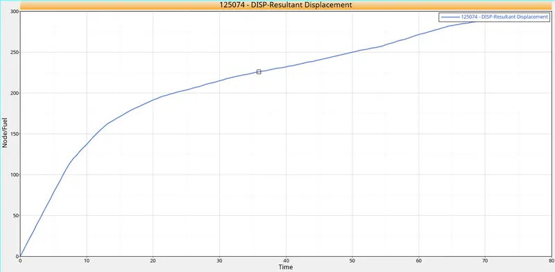
>As impact by side of the crash the impact force to at fuel section at starting increases and end of collapse at a point
>AT B PILLAR :
>FINALY IMages of side crash
EXPLANATION :
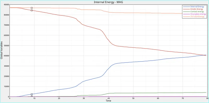
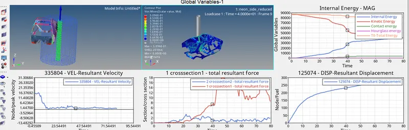
>KINEMATIC ENERGY :
Kinetic energy is the energy an object has because of its motion. After work has been done, energy has been transferred to the object, and the object will be moving with a new constant speed. The energy transferred is known as kinetic energy, and it depends on the mass and speed achieved.
The equation of kinematic energy = 1/2mv^2
>While applied to the velocity to the component,the intinally velocity too high and velocity is decreasing with respect to the time , because of the deformation constants in the component
>So, kinematic energy is directly proportional to the velocity , that the reason while kinematic energy decreases gradually (as shown in the plot graph)
>The best example of energy transfer from an object as shown in below image:

>INTERNAL ENERGY : Mathematically U = Q-W,Here neglected the heat because we are in the solver,as from the internal energy are depends on the displacement. in the starting there is no displacement in the component. that's were the internal energy starts from zero. when its subjeted to acceleration there will be a displacement, the internal energy increases its the displacement also increases.that the reason from raise of internal energy curve as shown image in plot

>TOTAL ENERGY: As there is no potential energy is not ploted , therefore the total energy is directly proportional to the kinematic energy,where the kinematic energy decreases then the total energy also decreases
>HOURGLASS ENERGY: There will be zero deformation that why the elements are undergo an hourglass effects strain is not consider,because there will be no physical stabilization,so,that to balance the energy,artificial energy is required to control of hourglass that's hourglass,so there is a lot of hourglass energy needed
>Outputs Understand :
>The main purpose of simulation of the front crash simulation is to occupied of the safety and damage controls
>As created of cross-sectional, frames, intrusion and initial velocity and accelerometer
>Center of Gravity : The center of gravity (CoG) of an object is the point at which weight is evenly dispersed and all sides are in balance.
>Rigid Wall : Rigid wall is created in the HyperMesh because where the car is going to make collisions.
>Penetration: There should not be any penetration because nodes get penetrated in the element and cause failure in simulation, removal of penetrated nodes is necessary.
>Accelerometer: An accelerometer is a device used to measure acceleration of the body and speed of force in the car
>Intrusion: Intrusion is used to check that if the component is withstanding a crash making sure that the component does not fail.
>Cross sectional: To maintain the equivalent forces distribution in the car
>FRAME : It purpose of giving as the direction Frames are used only in notable options like imposed velocity, imposed displacement, TH/node etc
>SKEW: Skew is one type of reference coordinate system which helps in defining local quantities with respect to the global coordinate system
>Skew is one type of reference coordinate system which helps in defining local quantities with respect to the global coordinate system
>The example is the study of intrusions in the car through skews and crash simulations
>Peak Velocity: It is the highest velocity attained during the impact of the side body (object) at a particular time.
>INITIAL VELOCITY : intinal velocity defnes an initinal velocity on a group of nodes ,here unlike others function or curve is not required only velocity at x ,y,and z direction is enough