Week 12:Project-1-Meshing of Door Inner Panel Challenge
AIM : MESHING OF DOOR INNER PANEL
PROCEDURE :
> First import the given model
>Then Exact the mid surface, the model has different plastic complex with different thickness , so while exact of mid surface with auto mid surface then go with improper of mid surface , so that we should generate the manual mid surface of each part its better gives of proper and exact mid surface
>MANUAL MID SURFACE :
>First go with in hypermesh-geometry -surface edit -offset (shortcut key - shift f9)
>View mid surface and correct errors using the mid surface edits options such as of Geometry :(Quik Edit)(Shortcutkey f11)

Geometry cleanup :
- View midsurface and correct errors using the mid surface edits options such as of Geometry :(Quik Edit)
- Importing the geometry component
- Generating midsurface
- Simplifying geometry
- Refining topology to achieve a quality mesh
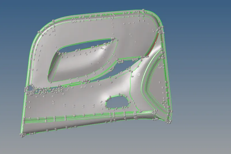
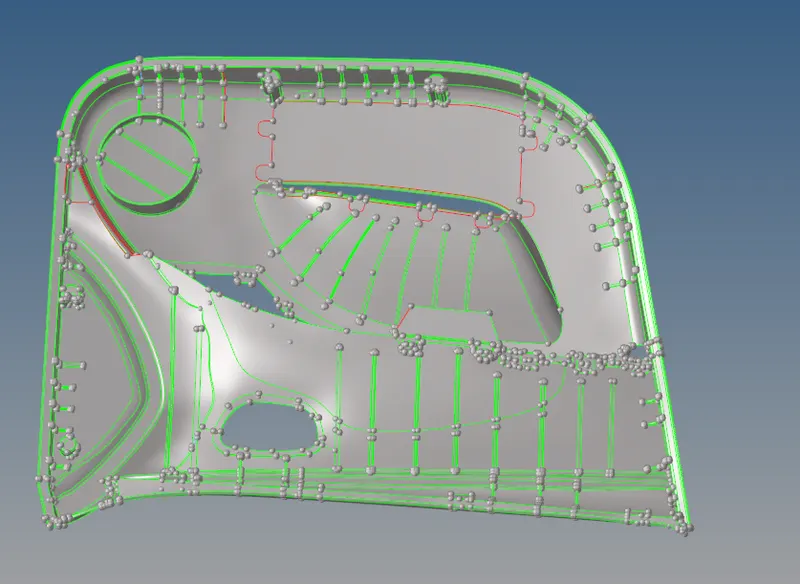
> THE GIVEN MODEL :
> THE GENERATING OF MANUAL MIDSURFACE(OFFSET) :
> In the model ribs are placed, so we can offset or create the mid line of ribs
> As the below of min size of value we can defeature the fillet areas and find out, finally remove
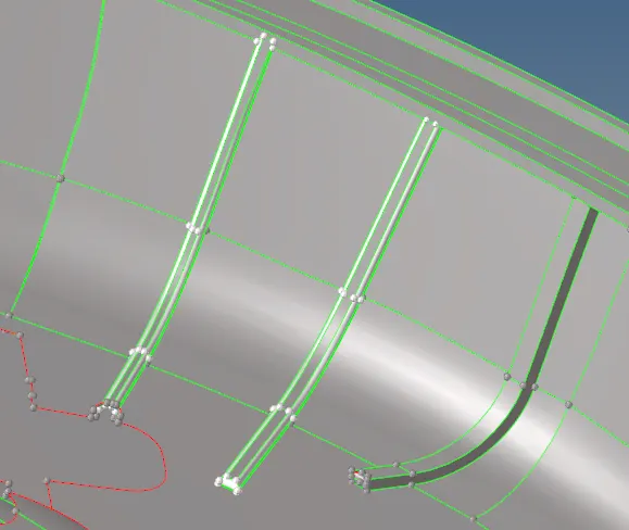
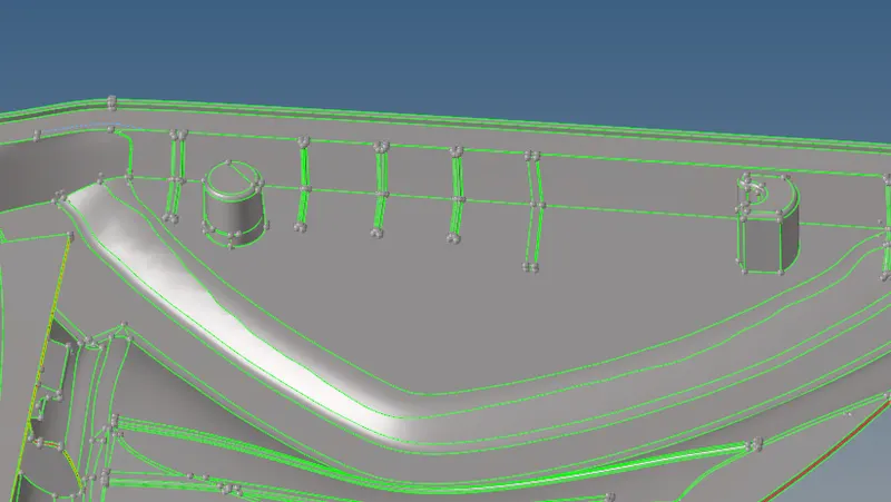
(a) Defeaturing the fillet areas and as shown in there highlight (b)
> while using the midline option :
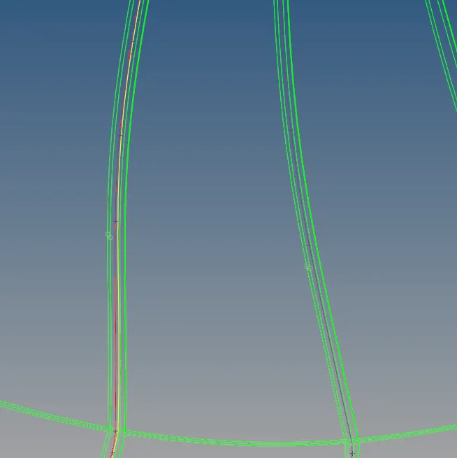
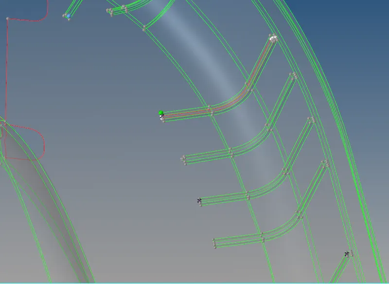
>see in the image the layer between the line is highlighted, then after generated the midline go with next trim that part with using surface edit- trim with sur/freeline - trim
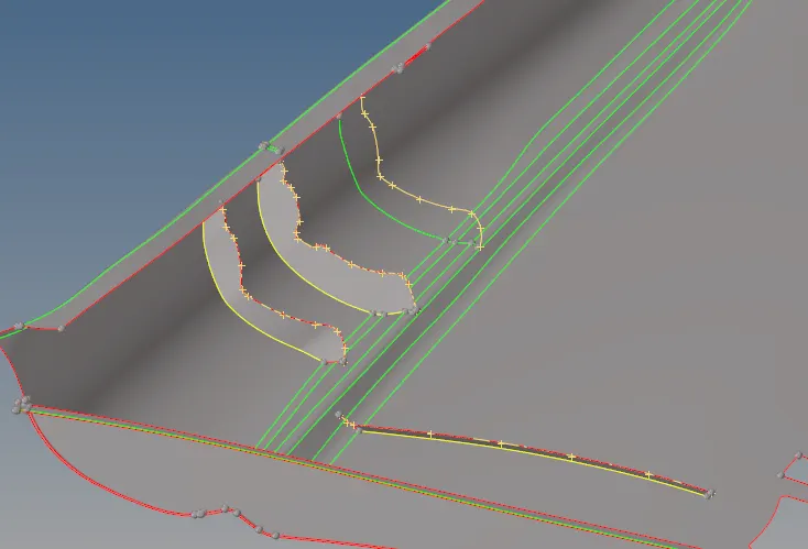
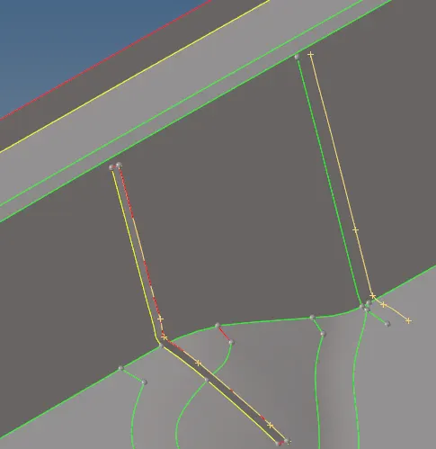
>after timing the completed then created the surface between the lines , and finally extend to the surface
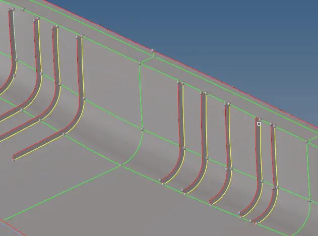
> same of generating with offset - surface edit
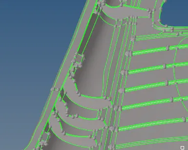
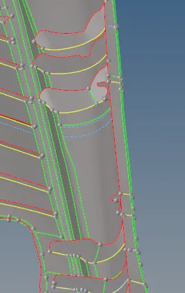
>The area which is having more than 6mm thickness should not model in 2D.
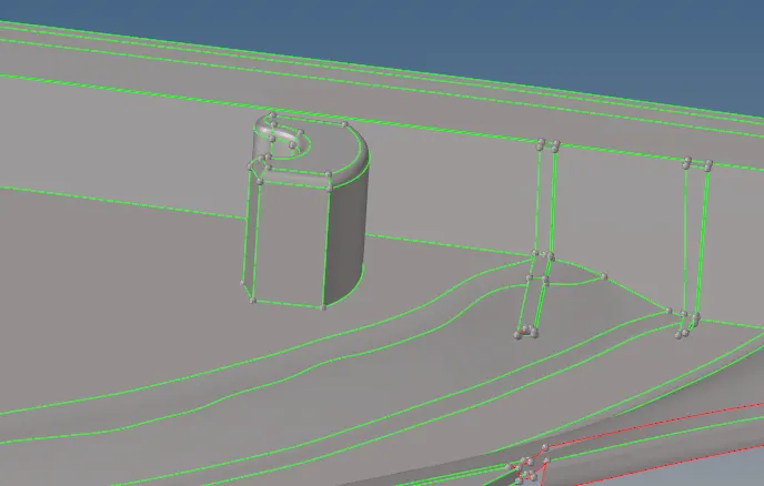
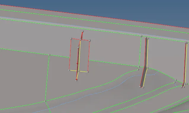
>The below image has some geometrical issue on it so modeling them in the 2D will be difficult.
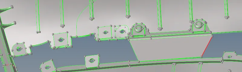
> By using the tools- project option-the lines to surface
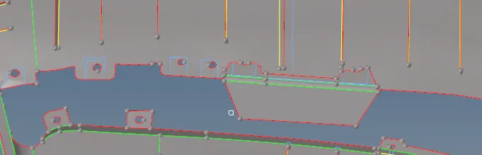
> I divided into two parts by given model trimed it and cut it into two parts :
>Part -1 :
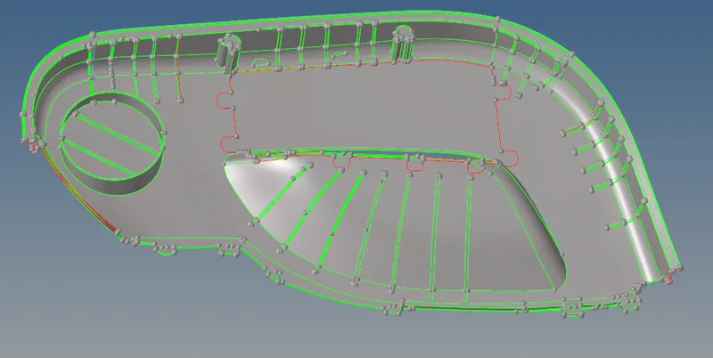
Part - 2 :
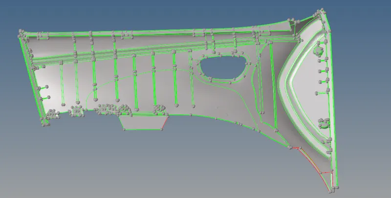
> AND FINALLY GENERATED OF MANUAL MIDSURFACE ( OFFSET) :
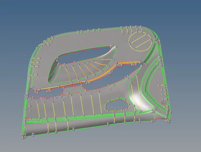
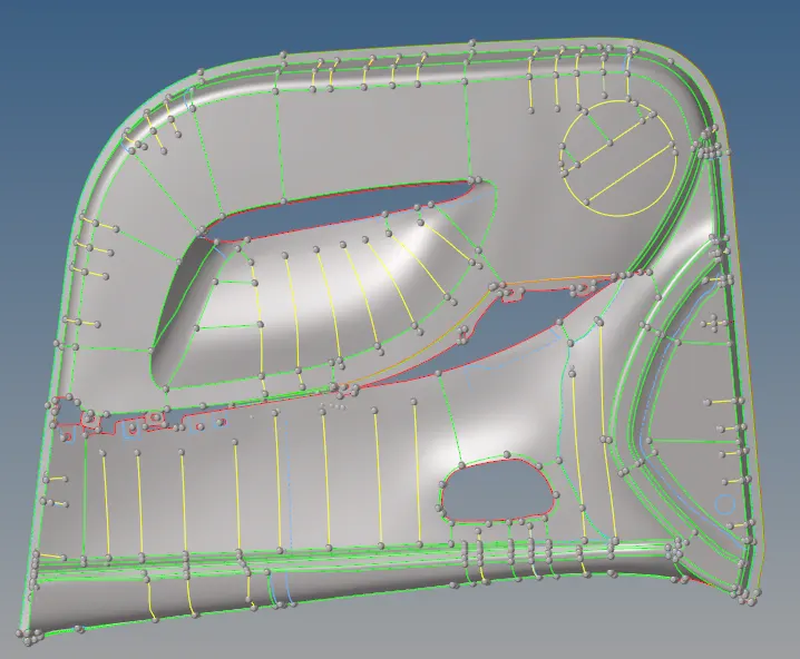
>GENERATING THE MESH :
>Then go with mesh the component (automesh - 2Dpanel )(shortcutkey f12)
>Mesh with mesh option type fixed
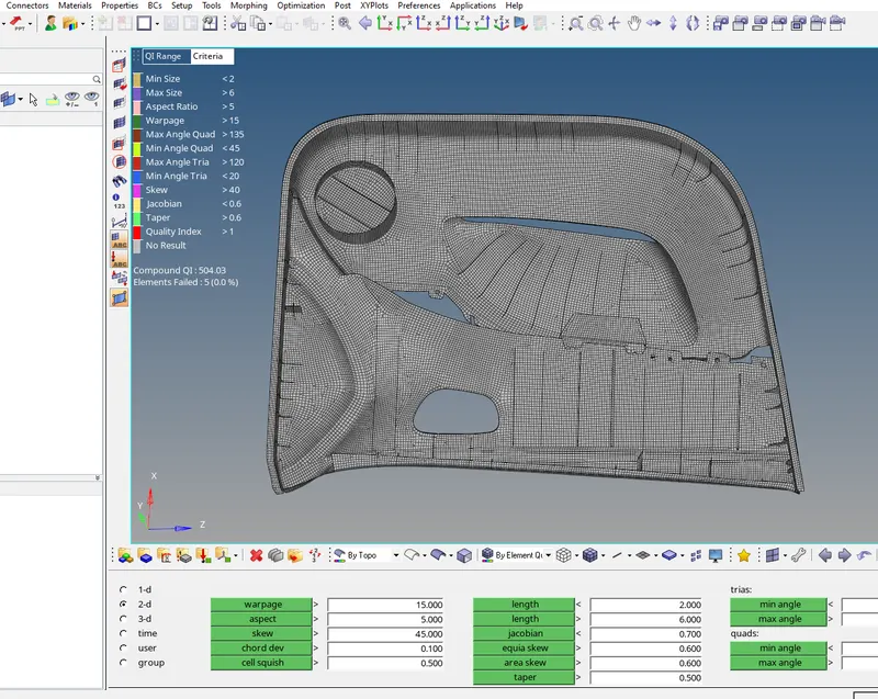
>The given values of required
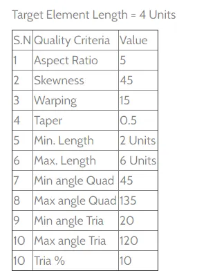
>Fitted into values in above of display (preference- criteria file setting) option
- BY given of above values to meshing the components
- After completing of mid surface exact ,then we go from the mesh the component
- 2D-automesh optionselested-then we go from while surf/elements option of doing the mesh
- shortcut key f12 (mesh)
- And selected of mesh type options
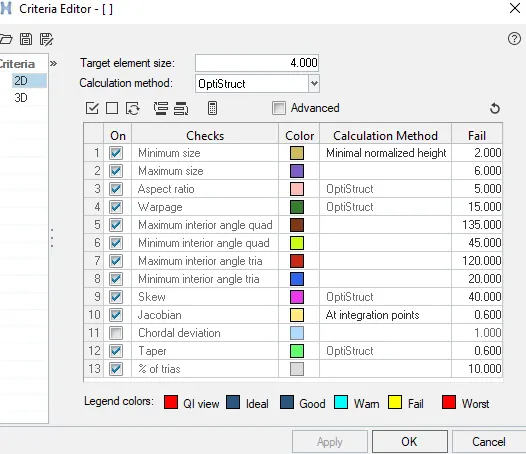
- BY the given of parameters values in hyper mesh
- Then go with above of display screen option- preference selected-criteria file setting option
- The option shows the failure of elements in the spot of doing the mesh
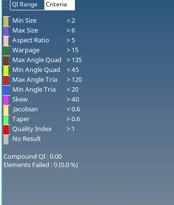
- While another option of better of optimization elements (QUALITY INDEX)
- select geometry 2D-quality index
- There are several option are held
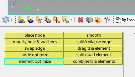
- After completing of mesh flow then go further nodes conductive of each nodes to nodes
- If further failer of nodes conductive ,selected of option to reduces the problem
- 2D-replace option selected
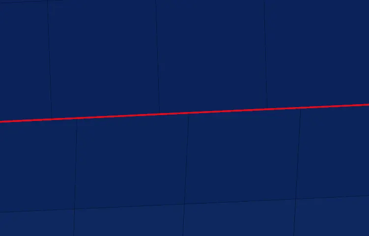
- And completely the mesh model then go with nodes equivalence or not , find edges
- shortcut key f3 from replace the nodes
- shift +f3, shows of finds edges

- shift +f3, shows of finds edges

- THe below of image showing find edges and replacing them nodes conductive
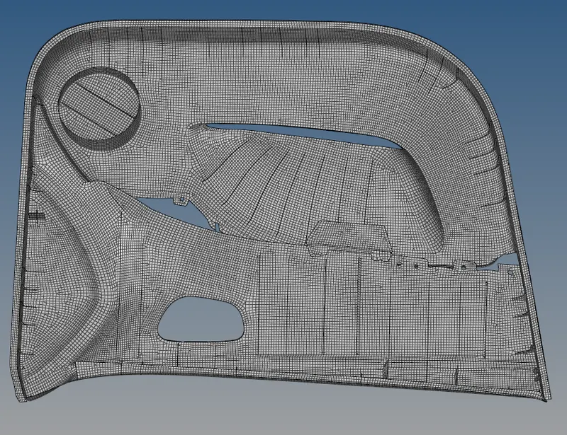
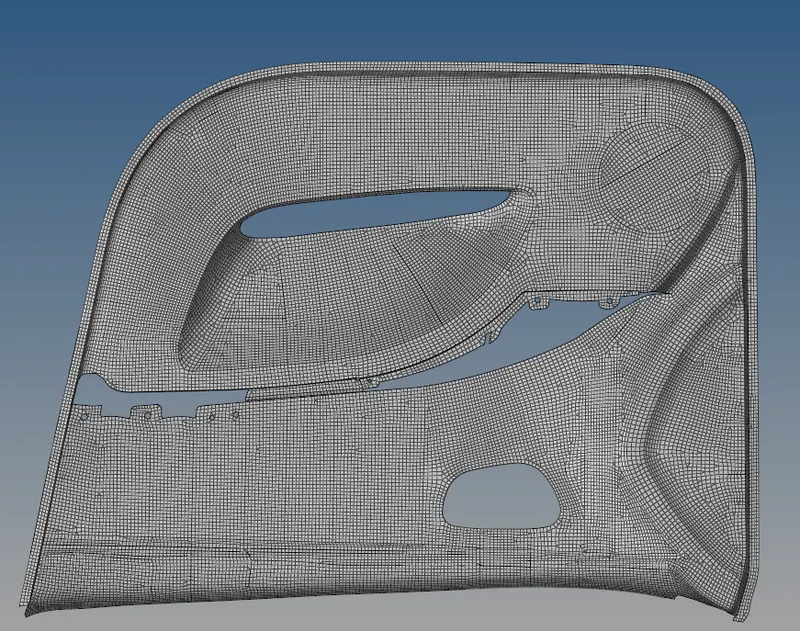
> AND FINALLY MESH COMPONENT OF DOOR INNER PANEL :
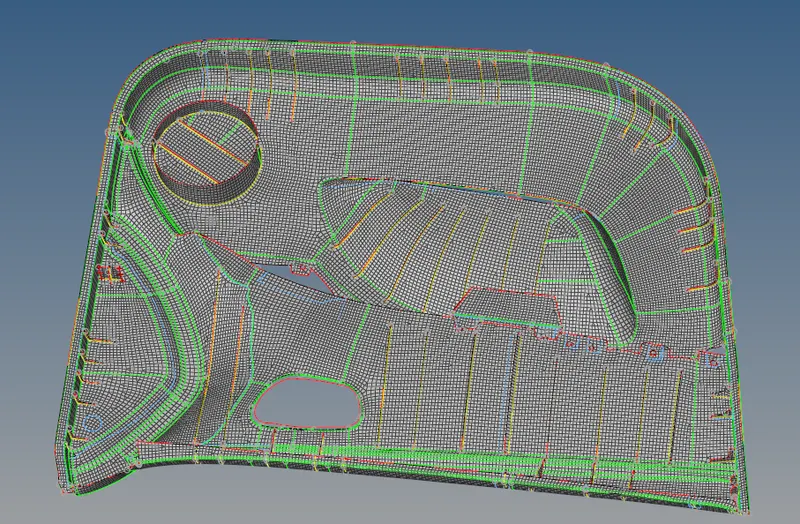
> Wireless mode option :
IMPORTANCE :
- WARPAGE :
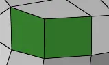
Warpage is the deformation thatr occurs when there is uneven shrinkage in the different parts of the molded component.warpage occurs when there are variations of internal stresses in the material.warped part may not be functional or visually acceptable
- ROTATIONAL :
> Rotational quards are the elements that are avoided in the analysis like crash,drop and impact where the flow of energy
>This why the rotating quad elements are avoided in the model as they distract or divert the flow of the energy in the model
>when the energy flow is distracted with the rotating quards than the actual physics of the problem(energy flow) is being modeled wrongly and as a results,the simulational is aslo not accurted.
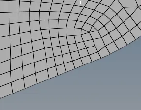
- TOPOLOGY :
- Topology repairs consist of correcting connectivity errors between adjacent surfaces
- Possible error include unconnected adjacent surface,duplicted surface ,missing surface
- The goal of topology repairs is restored surface data to a perfectly clean representation of the part
- TOLERANCE :
- The tolerance is the difference between the maximum limit of size and the minimum limit of size
- ELEMENT QUALITY : The element options is shows the failure elements , while doing the mesh
- SKWENESS ;
- Skweness is the angular measure of element quality with respect to angles ideal element type. it is one of primary qualities measure of FE mesh.
- Skweness determine how to close ideal (equliateral or equi-angular)
- ASPECT RATIO :
- Aspect ratio is a measure of a mesh elements derivations from having all sides of equally length
- A high aspect ratio occurs with long ,thin elements
- TO REDUCES THE MAX AND MIN QUAD ANGLE :
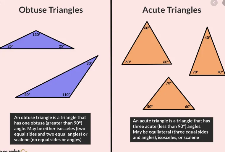
- By using the triangle formule are
- The less than 90 degree triangle is known as “ACUTE TRIANGLE”
- The more than 90 degree triangle is known as “OBUSTE TRIANGLE”
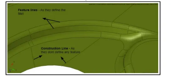
- FEATURED LINES : Any line which helps or directly involves defining a feature is said to be a feature line . a line that is represented for a plane change is a well called a feature line
- CONSTRUCTION LINE : any line which does not involve indefining the feature is said to be construction line
WHY IS GEOMETRY CLEAN UP : The geometry cleanup option allows you to 'cleanup' the model geometry by marking vertices which are very close to each other into a single vertex according to a definable spacing excitation
- SPLIT:
In case of such an indefinitely nodes shape we can use of help split option of dividing the line in between element node
Splint element in hypermesh:
From the edit element, we can use the split tool, to split edges/quads, combine trias and swap edges ,
Edit element split tool keyboard short cuts and mouse control
To do this press Button
Split element or edge Left-click
Combine elements Shift+left click
Swap element edge Ctrl+left-click
Exit tool ESC or right-click
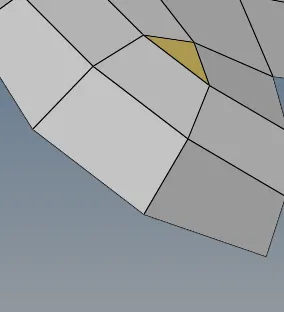 BEFORE SPILT
 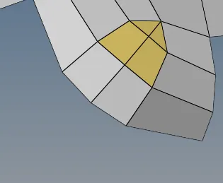 AFTER SPLIT
- TRIA ELEMENT :
A tria element is stiffer than quad elements .Because, A tria element will always in a plane because it take minimum of 3 nodes to specify the plane. A quad element can wrap if required depending on the applied force.
Triangular finite elements are stiffer in bendending problems because they have constant strain across the elements, this simply makes it impossible for an FE solver to calculate the bending response properly ,unless a lot of tria elements are used
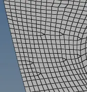
- When comes to tria elements ,there are few thumb rules to be followed
- No tria elements should be opposite to each other
- No tria elements should be connected back to back
- No tria elements should be on the edges of the geometry
- No tria elements should be near on the holes
- No tria elements should be on the feature and the fillet
- Finally, there should be less concentration
>THE DIFFERENCE BETWEEN THE MANUAL AND AUTO MID SURFACE: But whenever the complex plastic deal with different thicknesses,the auto mid surface algorithm is very high efficient,while exact of the mid surface then there of improper exact of mid surface , we can go with the manual mid surface. (MANUAL MID SURFACE WE HAVE TO FIX THE ERROR )
>MESH CONDUCTIVITY : If the force applied on the component,there of no conductivity,its will applies on the conductivity component
> ALways kept the option while doing the mesh ,because the interactive function of increasing and decreasing of nodes density while doing mesh
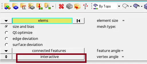
> Check the find edges(Shortcutkey shift f3):

> visible points on it by given tolerance value and equivalence them
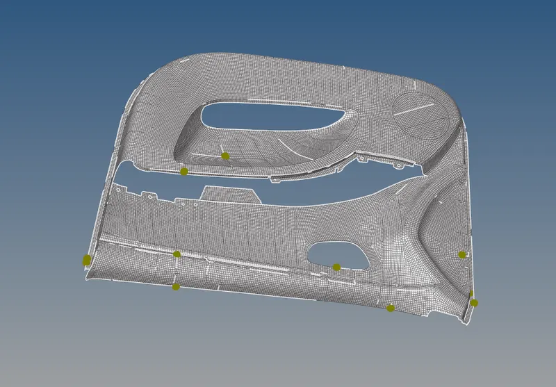
>Finally generated of mesh of given component door inner panel
>And quality element should of passed without failures :
>ASSIGN THICKNESS:(AUTOMATIC THICKNESS) :
>In order to represent FEA model similar to cad model , thickness will assiged to the 2d shell elements
>With the help of parent geometry , thickness will be assigned manually and automatically to the shell elements
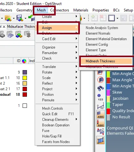
> Then ,
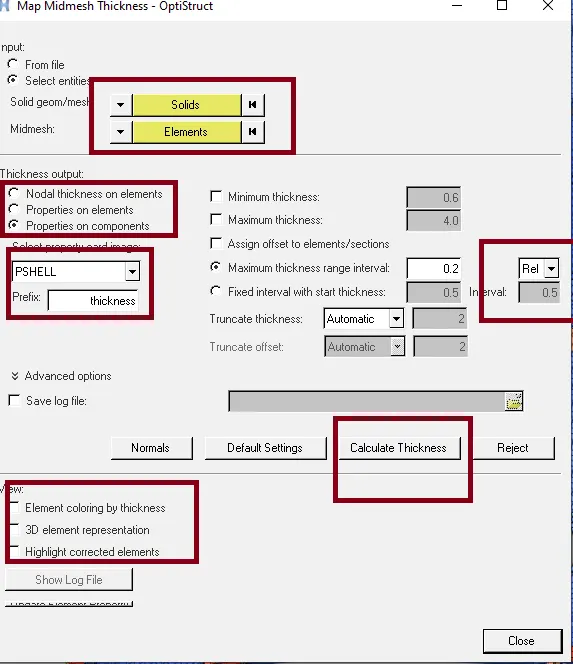
>As assigned the thickness to the model :
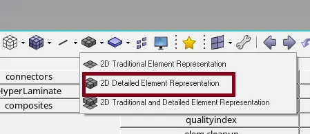
>View in as 2D detail representation element
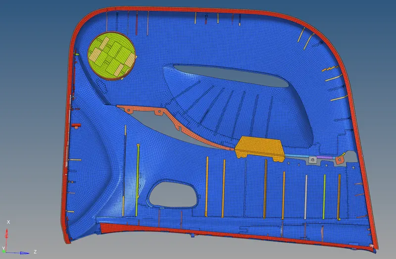
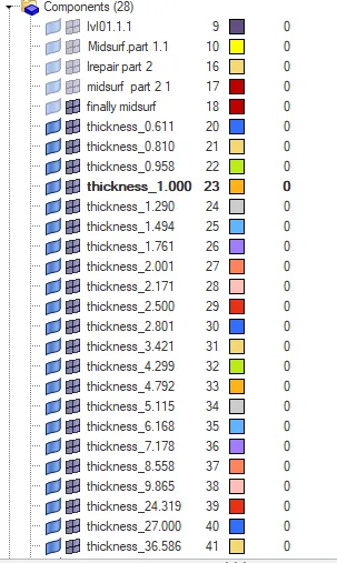
>And the components of the model :
> CONCLUSION :
>Generated manual midsurface and geometry clean up
>Generated mesh on the given component with low tria concentration
>And finally the given quality parameters are should passed
>Finally assigned automatic thickness to 2D shell elements