Week 4-1D Element Creation Challenge
- AIM: Create 1D elements on the following component with given cross-section and DOF
- Specifications ;
- Procedure :
- Firstly imports the given model
- Then shaded the model before going the mesh
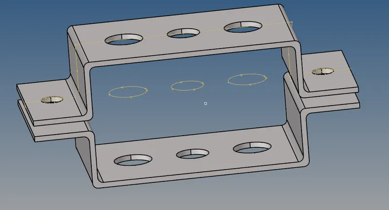
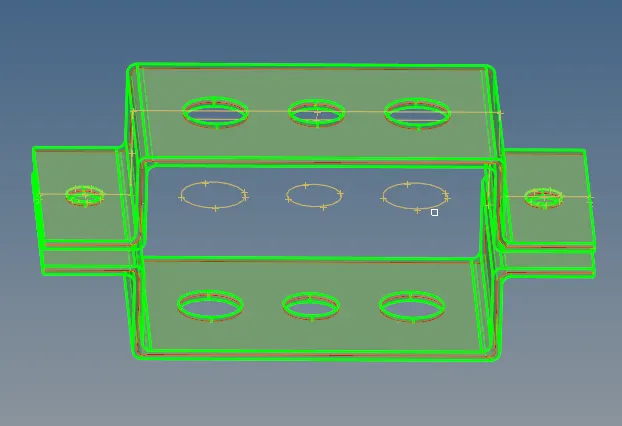
- Now surface of model midsurface to know of exactly were of surface bracket 1 and bracket2.
- After deleting the previous storage of bracket1 and bracket2 were shown in the below image:
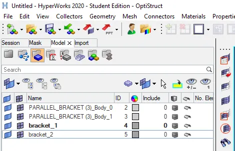
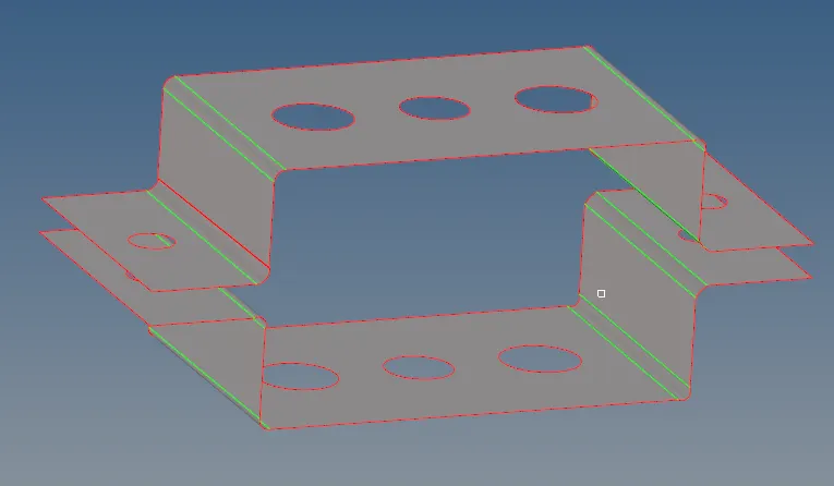
- while will requireds midsurface : without midsurface the no.of nodes are increase and no.of elements are increase which is turn to increase the storage space required to stogare the intered component,and processing analysis is also required, to avoid all this midsurface,where we can just represented the interied 3D surface and created shell elements in that, shell elements are represented 2D shell to 3D elements.
- Before going mesh we see of it while donig of circles to washerspilt as of 5mm off set value.
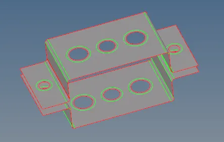
- Meshing The component :
- Mesh the Given component with the Size of 5 Units.
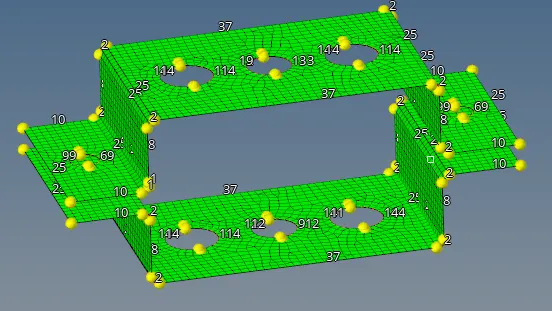
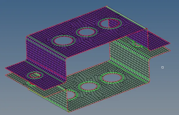
- check the after mesh component surface whether is goog are incorrect of surface layer ,were correction in that midsurface options.
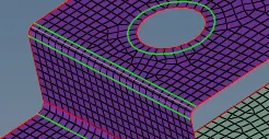
- Creating material component to given component
- As material is used steel
- Now giving the properties to that because the giving of thickness to bracket1 and bracket2
- Thickness(t) Bracket1 as 2.0mm
- Thickness(t2) Bracket2 as 2.5mm
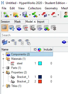
- while created of material,propertied,thickness
- Creating the property:
-
S.NO PROPERTY NAME CARD ID 1 Bracket_1 PSHELL 2 Bracket_2 PSHELL 3 ROD PROD 4 Beam PBEAM 5 BAR PBAR - creating Rigidt elements the Rbe2,Rbe3 and obtained mass and lines of Rod,Bar,Beam
- mass value is giving of 10
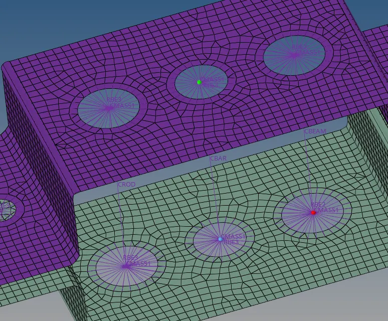
- creating Now 1D elements:
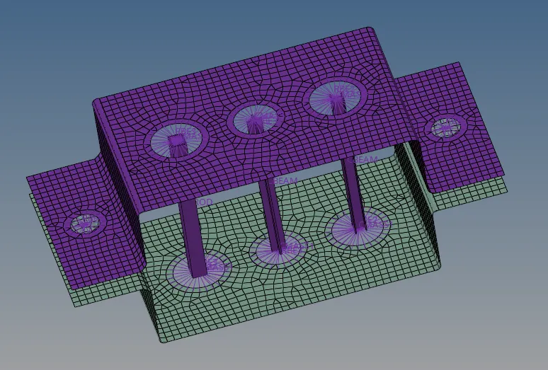
- ROD as box section as given as dimesion
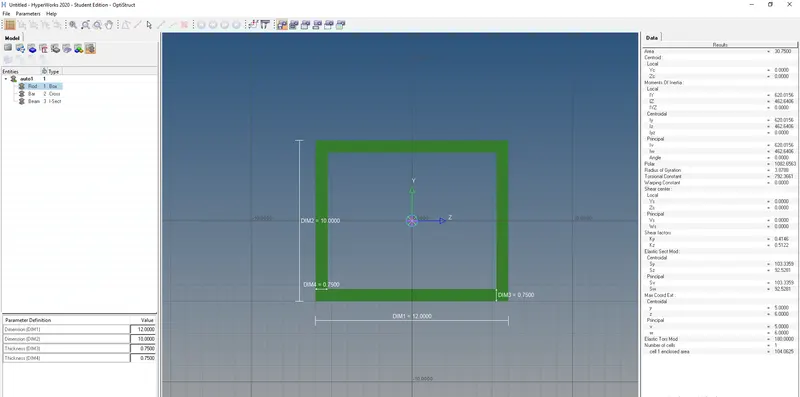
- Creating now BAR
- BAR x-section as given dimensional values
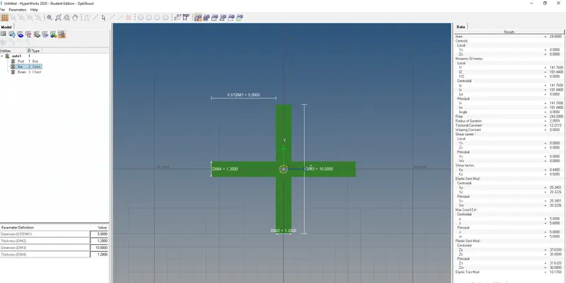
- Creating now BEAM
- BEAM I-Section as given dimensional values
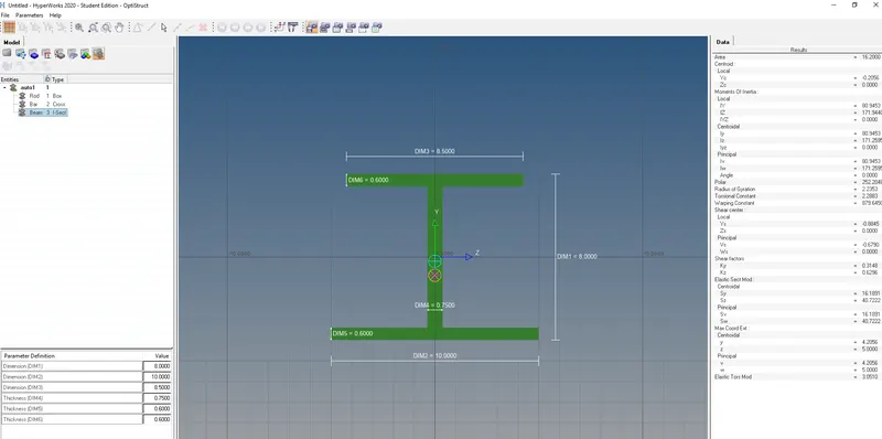
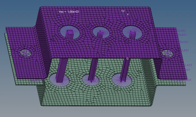
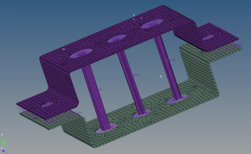
- Creating the 1D elements with respect to their properties
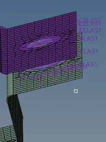
- Joining the two components with Spring elements :
- Now creating the Vectors and System
- By given dimensinal maginitude as value 10
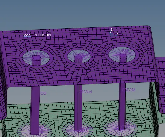
- 2D elements detailed representation:
-
- CONCLUSION:
- Extacted the mid surface for the given component and create a mesh on mid surface
- Deployed suitable 1D elements (ROD,BAR,BEAM,SPRING,MASS,RBE1,RBE3,ETC) to respective places
- Assigned Cross section and property to 1D elements
- Finally 2D detailed elements representation with 1D elements