Assignment 3-2D Element Formulation Challenge
AIM :
Comparison of results with base simulation and improved shell element properties
1.Using the crash beam file from the previous assignment, change the run time to 55 ms.
2. Change the number of animation steps during simulation to a minimum of 25 and maximum of 60.
3. Run the base simulation without any modification to element properties.
4. At the end of the simulation, do the energy error and mass error checks and determine whether results would be acceptable.
5. If acceptable, Plot rigid wall forces, internal energy, hourglass energy, contact energy, total energy of the simulations.
6. Change all the shell elements properties to recommended properties, save this as separate, rad files and run the simulation.
7. Follow steps 5 and 6.
8. Create a brief report comparing all the results from steps 5 and 6 for both simulations.
9. Comment whether there is any change in the results and why there is any change in the result.
EXPLANATION :
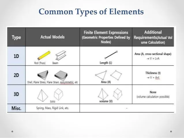
>ELEMENT FORMULATION : The process of a FEA discretizing an infinite component into finite element. this discretitation process is carried out not just with one particular type of element. a component discretized usinng 1D,2D and 3D element based on the requriment
Formulation are kind of element defining that elements behaviour and properties
>There are based of 3types of elements,There are :
>1D : Elements which includes Truss,beam,and spring
>2D: which includes of 4nodes shell elements (quad)and 3nodes(Trias)
>3D : which includes of solid elements ,Treta and Hexa elements
NOTE :
>While Before going the 2D element formulation that we have to discuss on one of important "WHAT IS HOURGLASS" And "HOURGLASS ENERGY "
>HOURGLASS :
>It is a wired mode of deformation that occurs in order integrated shell elements where no stress are produced
>Its stresses are not produced its reduces the accuracy and have the response of the structure
Note :
"The mean aim of the hourglass is zero deformation energy "where elements are seen to be deform.
>There are two method of used to control fromulation of hourglassing are :
>PERTURBATION (QH4 element)
>PHYCSICAL STABILIZATION (QEPH element)
>Perturbation method :
>Perturbation (viscous) method Ishell = 1,2,3,or 4 (Q4)
>When hourglassing is detected, a force is applied on the node to stabilize the deformation.
>This force introduces an artifical energy (named hourglass energy )
>Physical stabilization method :
>Physical stabliization method Ishell = 24(QEPH) = stiffness method
>Hourglass loading stifness depends on natural tangent modulus
>The hourglass treatment is done at the material level .
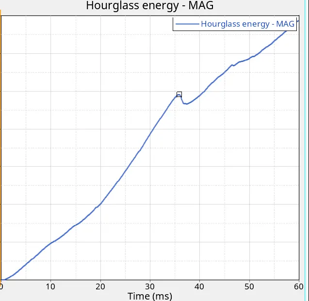
>As showing above in image hourglass engery plot graph
PROCEDURE :
>CASE 1 : ( without giving any recommended values in the property )
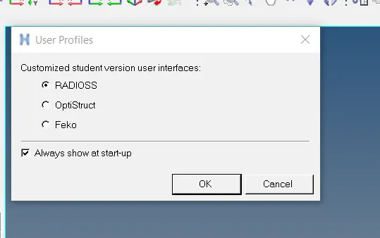
>Firstly import the model, while we are using the radioss profile ,because we performing analysis
>Then import the file rad0.0000
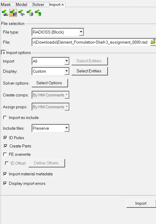
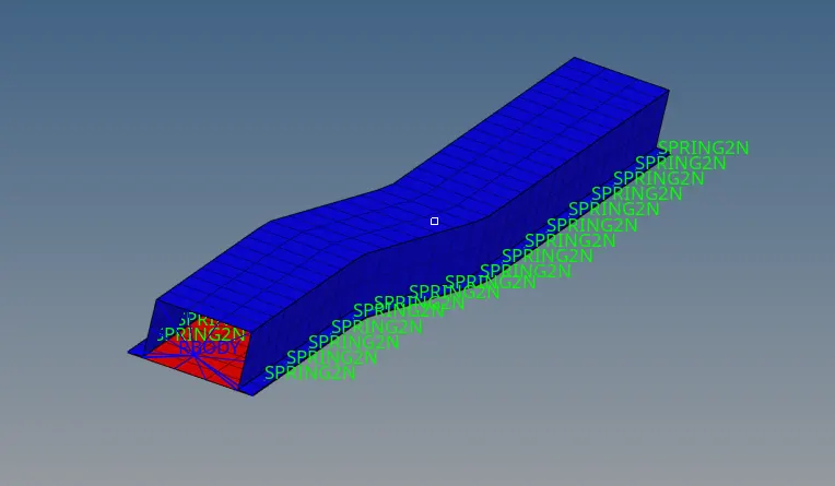
>Now see the model :
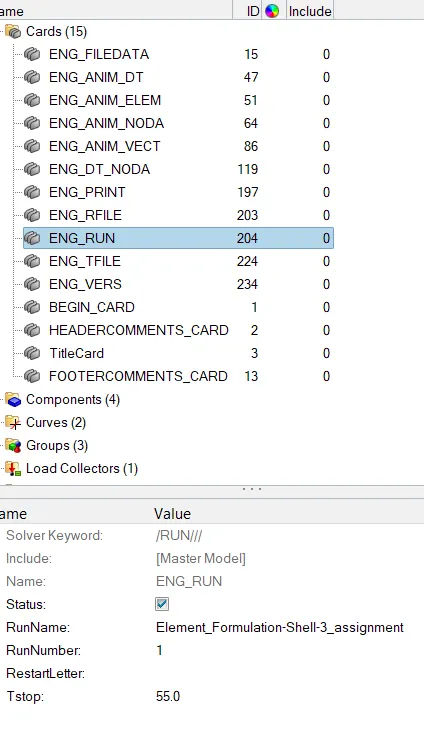
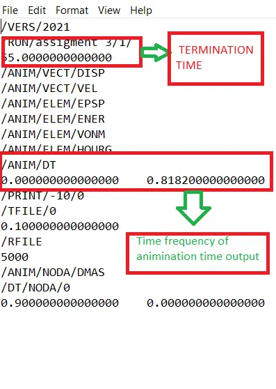
>Now next step assign the valuues of giving in question as Run_time and Anim/DT value time freq :
>As per given in a question of runtime (Tstop value change 55ms)
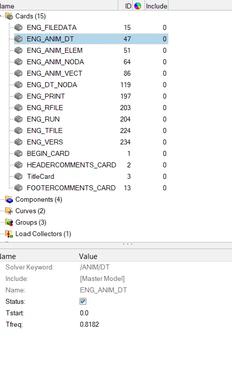
>Next we have to find or select of no of animations steps required. as given in the question mentioned the during the simulation change maximum value 60 and a minimum 25 in between them. i was selected of 45 value.
>Now the foemulae to be used to get of it : Time step `div`No of animation step
=55 `div`45
time frequency = 0.8182
>Now the entered this value in card image "ANIM/DT" value:
>Then after entering and changing the values of timefreq and animation engine card , to perform the simulations
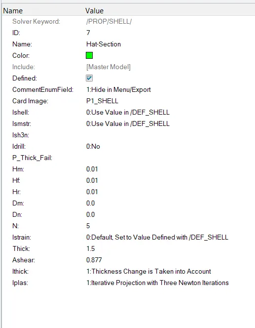
>while going to run the simulation but were without assigning the properties values to the given component ,the parameter in the property are taken the default values
> Next step we have run simulation that we needed of analysis-radioss panel

>After intering the radioss panel, then input the file given of 0.0000rad file intinally , then export option take as all , run option same ausally analysis, run number as put 1 , main important steps in the option as put the value of (-nt 4) , it means of assigning the task of 4 times of run the perform the simuation faster , it depends of our computer processor
>And "-nt " is number of threads , after giving and setting these values go with run simulation radioss

>Next step to check the values , whether after simulation run of runtime and timefrequeny in the engine card
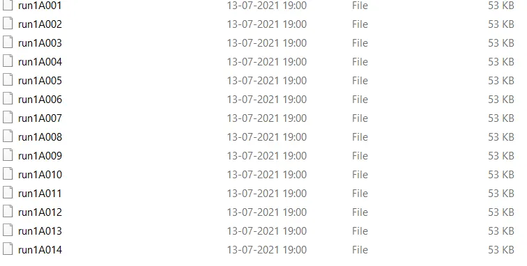
>Now check the animination file were number of animination step obtined in file location
>Now check the values of energy errors, mass-energy,internal energy , energy error, and total energy as in the file of (run_0.0001) file selected

>Now whle scrolldown the bottom we can see the maximum value of energy errors,mass energy and internal energy , kinematic energy of obtained as maximum values
>Energy error -11.2%,internal energy,internal energy:0.218E+08,Kinematic energy:0.1469E+05,mass error : 0.1659E-03

NOTE :
> The acceptable range of energy error are -15% to +5%
>Now go with hyperview in hypermesh, it will show as direct as inputs file h3d file format ,then click on apply buttom to view and run the simulation
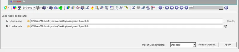
>Then after inputs file of h3d it will appear of :
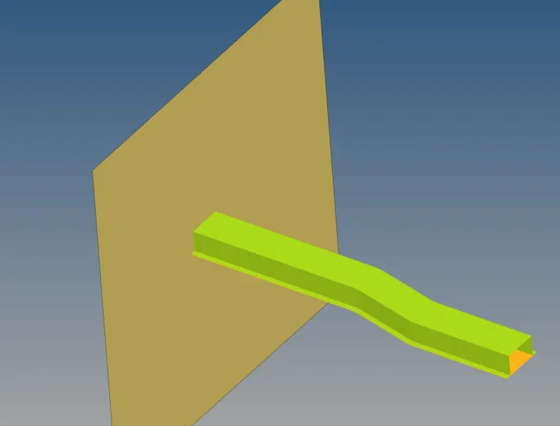
>Next will go with contour option :
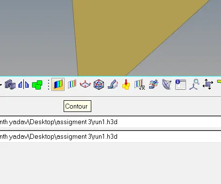
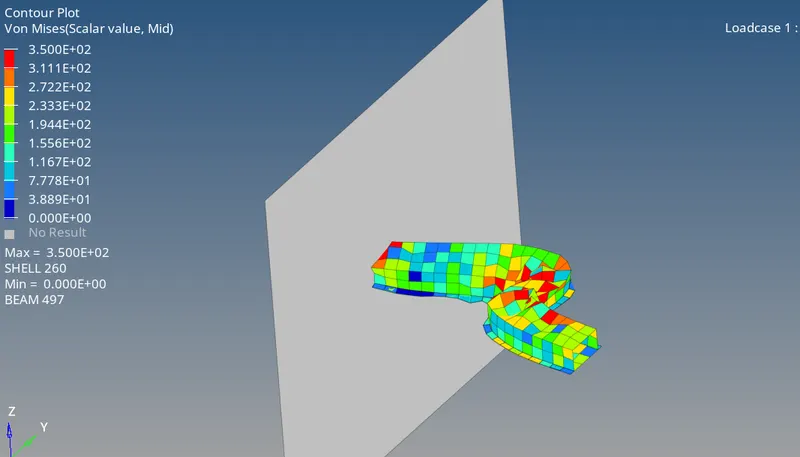
>After clicking the countour we visible as :

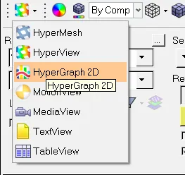
>The next step is post processing,this will obtainted of various graph for the above simulations ,then it will swited to hypergraph 2D
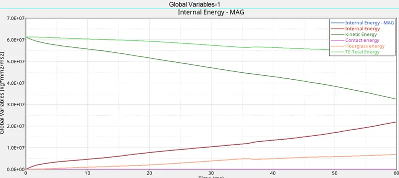
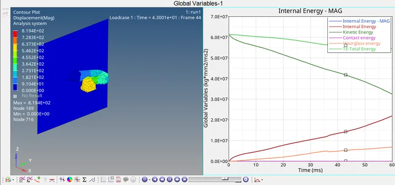
>The next step is plot the graphs of different energy indicates were some of important are kinematic energy,internal energy,contact ant total energy ,and hourglass,and applied in the 2D hypergraph
>
>WERE comparing of both :
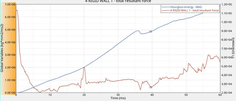
>Rigid wall force obtaining will appears of :
EXPLANATION :
>KINEMATIC ENERGY :
Kinetic energy is the energy an object has because of its motion. After work has been done, energy has been transferred to the object, and the object will be moving with a new constant speed. The energy transferred is known as kinetic energy, and it depends on the mass and speed achieved.
The equation of kinematic energy = 1/2mv^2
>While applied to the velocity to the component,the intinally velocity too high and velocity is decreasing with respect to the time , because of the deformation constants in the component
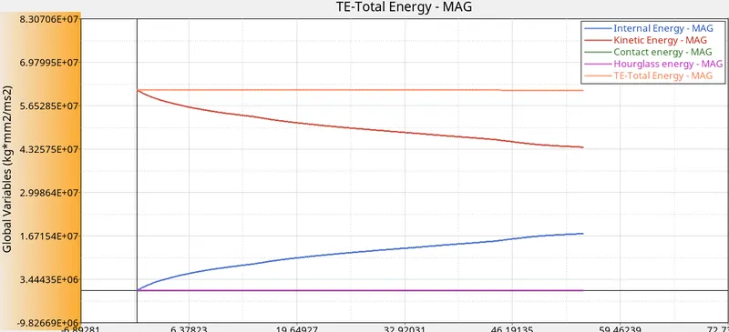
>So, kinematic energy is directly proportional to the velocity , that the reason while kinematic energy decreases gradually (as shown in the plot graph)
>The best example of energy transfer from an object as shown in below image:

>INTERNAL ENERGY : Mathematically U = Q-W,Here neglected the heat because we are in the solver,as from the internal energy are depends on the displacement. in the starting there is no displacement in the component. that's were the internal energy starts from zero. when its subjeted to acceleration there will be a displacement, the internal energy increases its the displacement also increases.that the reason from raise of internal energy curve as shown image in plot

>TOTAL ENERGY: As there is no potential energy is not ploted , therefore the total energy is directly proportional to the kinematic energy,where the kinematic energy decreases then the total energy also decreases
>HOURGLASS ENERGY: There will be zero deformation that why the elements are undergo an hourglass effects strain is not consider,because there will be no physical stabilization,so,that to balance the energy,artificial energy is required to control of hourglass that's hourglass,so there is a lot of hourglass energy needed,so the hourglass energy starts with the origin and to goes on increasing(Shown in the plot graph)
>CASE 2 : (Assigning with proper recommended properties in the property)
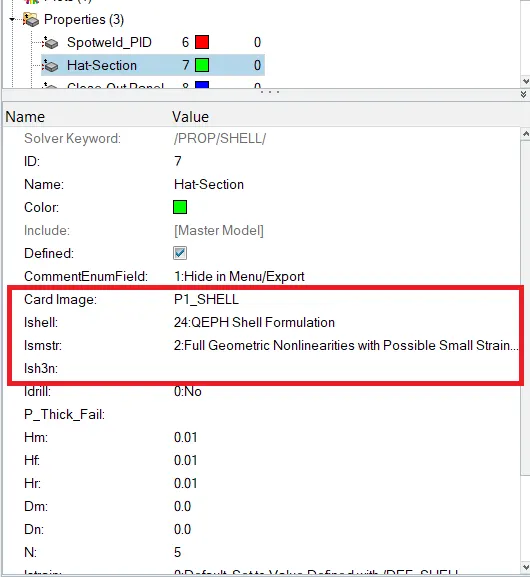
>Assign the properties values of recomended values in the property
>As given in the question values entered
>After entered properties into property value
>PROCEDURE :
>As same of case 1 procedure , after open with anaylsis- radioss
NOTE :
>Save file separeted in folder beacuse we should compare the result case 1 and case 2 as animition files also
>Now check the values of energy errors, mass-energy,internal energy , energy error, and total energy as in the file of (run_0.0001) file selected
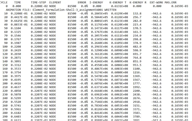
>Now whle scrolldown the bottom we can see the maximum value of energy errors,mass energy and internal energy , kinematic energy of obtained as maximum values
>Energy error -0.1%,internal energy,internal energy:0.1745E+08,Kinematic energy:0.4380E+08,mass error : 0.1659E-03

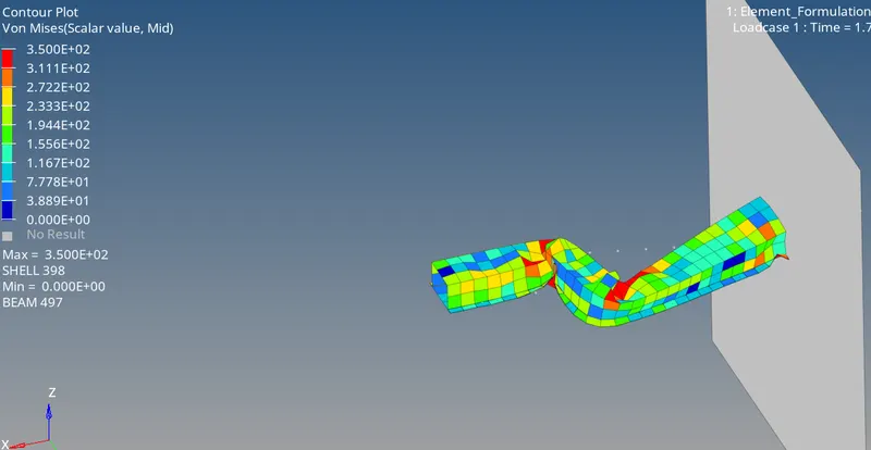
>After given i was selected of von misess view, it will appears of :
>In post processing various graphs are obtainted ,the process of obtaining the graph in the same as case-1
>The next step of graph the various plots internal energy,kinematic energy,contact energy,total energy and hourglass energy
>But there are some change in small rise in total energy and hourglass is contant while comparing with case-1
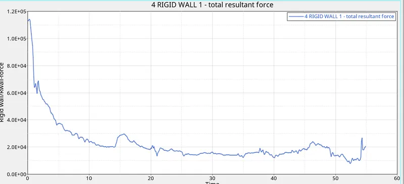
>The obtained rigid wall force graph :
>There are some improment in rigid wall force with comparing of case 1
>Comparing the both results which we are obtainted results as case 1 and case 2 :
| Campersion of results obtined | Case 1 | Case 2 |
| Results of maximum energy error | -11.2% | -0.1% |
| output of maximum internal energy | 0.718E+0.8 | 0.1745E+0.8 |
| obtained of maximum kinematic energy | 0.1469E+0.8 | 0.4380+0.8 |
| Hourglass energy | varuios of hourglass | Contant hourglass |
| Contact energy | energy which of same contant | Energy which of same contant |
| Result | Less accurate | the results are accurate |
| Rigid wall forces | By graph increasing and up and do of plot show and finally getted of deceasing the value | By comparing of case 1 some of rise in improvement |
| Needed of Hourglass energy | The element doesn't have physical stabilization (because of zero deformation energy ) | The element have stabilization because of after assign the recomended parameters values to property card |
| The reqired of hourglass energy | The reqired of houglass Beacuse of the energy balance | No needed of hourglass energy because of contant energy |
>UNDESTAND OUTPUTS :
>While the experience of comparing the without assigning properties value to the property card and with assigning the recommended properties to the property card image, to get off accurate result while performing the simulation
>undestand the energy errors , were of internal energy ,total enegry, kinematic energy, mass-energy and hourglass with the help of 2D plot graph
>Undestand of changing termination value and animation time-frequency output values
>By the animation file understand the deformation of elements with energy errors, variation with results of plots by hypergraph 2D and the hyper view
>Undestand how to run the simulation, post-processing by given rad file(0.000rad)
>Undestand the hourglass energy and how to control methods of hourglass energy
>Undestand of the basic information while performing the simulation Steps were of :
>STEP-1
>Check the 0.001.out file
1.Mass error:(allowed 5%)
2.Energy error :(allowed 15%)
STEP-2
>Hyperview
>Animation
STEP-3:
>Hyper graph
1.open T01 file
2.plot
>Global variable:
- Kinematic energy
- Internal energy
- Total energy
- Contact energy
- Hourglass energy
STEP-4
>Contour result
1.Displacement
2.Velocity
3.Acceleration