Week -2
AIm: Make a Simulink model of Doorbell using a solenoid block with the following details
In the above arrangement, when the switch is closed the electromagnet receives electrical power from the battery and pulls the metal arm to hit the bell producing sound.
Create a situation where the switch is closed for 2 seconds and then released. Observe the physical movement of the plunger.
>Procedure :
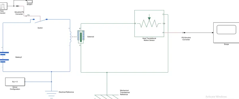
>The block model of doorbell using solenoid
>Firstly make of electric resistance and mechanical translation part separetes
>The electric resistance consists parts of pulse generator,switch,battery,solver configuration (F(X))=0
>The mechancial translation consists of solenoid ,ideal translational motion sens
>EXPLANATION :
>As seen the block diagram firstly created the pulse generator to switch in between them converted the Simulink to ps converter
>Then switch to battery converter were end of created the electrical resistance part because of its electrical part moods and other solver configuration created because of the whole model to know whether simulation run of software but we know that the model block but solver doesn't know of it so then we creating the solver configuration F(x) = o
>Now creating of the solenoid (Rport and Cport (conversion port ) were cport connected with cport only and rport is connected to Rport of ideal translation motion sens then changes to position (p) is connected with scope in between them the connected of ps to Simulink converter
>The solenoid its means the regrading the winding parameters wire and after passes the current then its iron core material absorber it solenoid then it pass curent output at translation direction only that the reason from using the ideal translation motion sens
>Ideal translation position(p)With the connection of ps-Simulink to the scope end which is but final output at the end whole part consider under of mechanical reference so that we were given name as mechanical reference function
>The battery is connected series to the switch part
>THe plotted of Doorbell using solenoid:
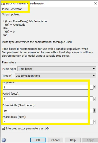
>Changing values in the pulse generator because we have the condition as when the switch is closed at 2 sec
>Here we increasing the pulse width and period sec
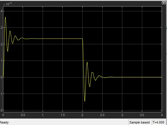
>The output result of scope :
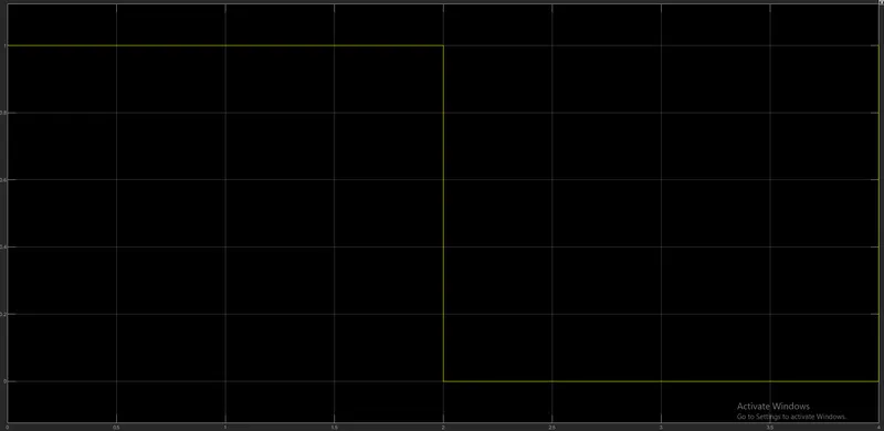
>THe input scope :
>OBSERVATION OUT PUT :
- Giving input as the time period for 2 seconds in the pulse generator to open & close the switch. When the switch is closed the solenoid block receives electrical power from the battery and the plunger moves from port R to port C to hit the bell & produce sound.
- The physical movement of the plunger is observed by using a translational motion sensor & physical output is converted into a Simulink output model is displayed in the scope.
>AIM :
Create a Simulink model of the thermistor to sense the temperature of a heater & turn on or turn off the fan.
Conditions:
Temperature source: 20 °C from 0 to 10 seconds, 27 °C from 10 to 30 seconds, 23 °C from 30 to 50 seconds.
Fan conditions: ON if the temperature above 25 °C, OFF otherwise.
Blocks used in model:
- Repeating Sequence Stair
- signal bulding
- Controlled Temperature Source
- Thermistor
- Thermal resistance
- Voltage sensor
- Battery
- Switch
- Scope
- PS-Simulink Converter
- Simulink-PS Converter
- Solver Configuration
Simulink Model:
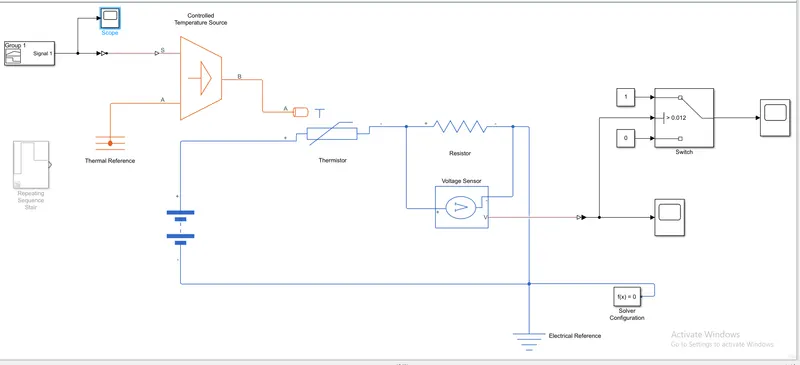
>Model explanation :
>Firstly we created the signal building part it will give the input value of temperature we can see in the input value in the scope
>controlled temperature source is gives temperature required value with connecting of signal function ,and the controlled temperature block consider of sport and Aport the Aport consists of ground level react thermal resistance function
>Now created the Thermistor block which shows us the NTC (Negative thermistor )thermistor relation between temperature and resistance.
>The thermistor consider of two types of Ntc (Negative thermistor)and Ptc (positive themistor)the difference between them the Ntc were the surrounding temperature increases then the resistance will decrease and the Ptc as outside of temperature increases the resistance also increases,here in this model were used of Ntc
>Now we creating the series resistance is connected with of battery and in the parallel voltage is connected,and one end of voltage (v)is connected of scope in between we use of Simulink to ps and switch is also connected
>In this switch we connected the two content block because we have condition fan on/off ,so then on =sysmbol1 and off = 0 and switch to connected of another scope because in the condition as given 25degree
>Final we created the solver configuration F(x)=0 and electrical reference function
>We have three scopes first scope is connected of input value result and the second scope is placed at 25degree of result and the third scope is the final output result
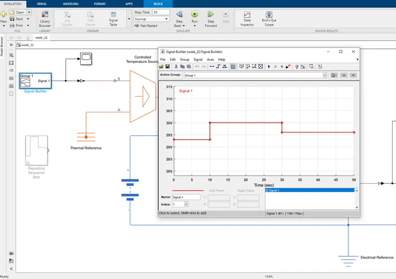
>Signal Builder - To generate the signal according to the input condition given.
>As we change in the model at first -20 °C from 0 to 10 seconds
>Second -27 °C from 10 to 30 seconds
>Third - 23 °C from 30 to 50 seconds.
>Explanation of model block use :
- Signal Builder - to generate the signal according to the input condition given.
- PS-Simulink converter: Converts Simulink signals to the respective physical signal.
- Controlled temperature source: (CTS) Provide a temperature physical output based on the condition given to port S.
- Thermal reference: Thermal reference block provides the required initial conditions to the connected thermal block for the solver.
- Thermistor: Thermistor block which shows us the NTC thermistor relation between temperature and resistance.
- Battery: Battery is a storage device that provides the required voltage based on the parameter given. We can use DC voltage source blocks too.
- Resistor: Resistor which provides the opposing nature of current in a circuit.
- Voltage sensor: This is used to measure the voltage or potential difference across any electrical component and it should connect in parallel only.
- Electrical Reference: These domain-specific electrical reference blocks will provide the required initial conditions to the connected thermal block for the solver.
- Solver Configuration: The Solver Configuration block specifies the solver parameters that your model needs before you can begin simulation and this is mandatory for all simscape designs.
- PS-Simulink Converter: Converts physical signals to the respective Simulink signal.
- Constant: Provides a constant output value
- Switch: This block is used from the library Simulink / Signal Routing where it has three inputs namely Port1, Port2, and Port3. Port2 is a control input where the signal given to port2 is satisfied with the condition and threshold of the switch block then it passes Port1 as output and if it is not satisfied then it will pass Port3 as output.
- Scope: This is an output block that shows the signal with respective time in an X-axis.
>After Run the model Result Observation :
>Input value graph :
>Total run time t = 50
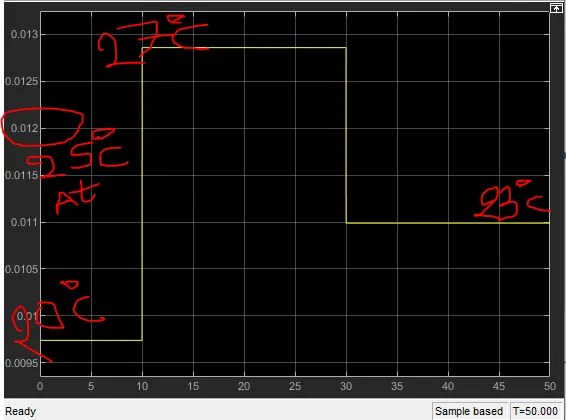
>Output value result graph :
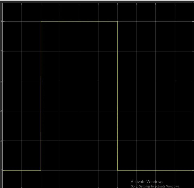
>OutPut Observation :
>As the result graph plot at 0 to 10 sec time the temperature is below the given temperature so that the fan switch will be (off) (20 +273=293k)as the temperature is in degree as convert into the kelvin
>Now absorber that at current passes 10 to 30 sec the graph will increase because of at cross the above 25degree temperature so that its meaning the fan switch will (on) at 10 to 30 sec of time (27+273=300K)
>While passing next at 30 to 50 sec of time the graph will decrease because at will representation below temperature ,so that its meaning the switch is (off)position at (23+273=296K)
>THEORY EXPLANATION :
>Thermistor :
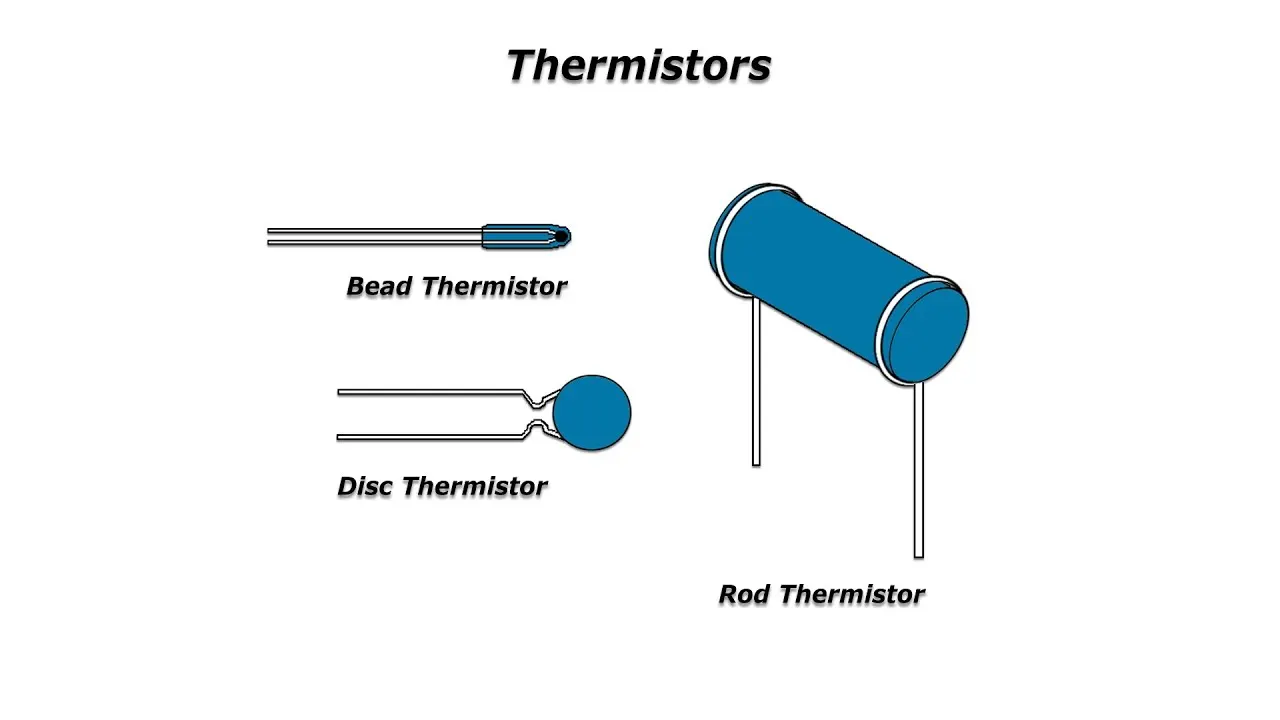
- A thermistor is a resistance thermometer, or a resistor whose resistance is dependent on temperature. The term is a combination of “thermal” and “resistor”. When temperature increases, the resistance increases, and when temperature decreases, resistance decreases
>RESISTANCE :
- Resistance is a measure of the opposition to current flow in an electrical circuit. Resistance is measured in ohms
>VOLTAGE :
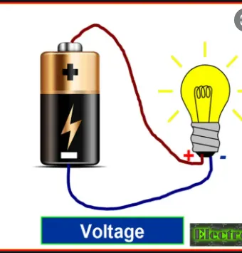
- Voltage, also called electromotive force, is a quantitative expression of the potential difference in charge between two points in an electrical field. A direct voltage maintains the same polarity at all times. In an alternating voltage, the polarity reverses direction periodically.
>Solenoid :
- A solenoid is a device comprised of a coil of wire, the housing and a moveable plunger (armature). When an electrical current is introduced, a magnetic field forms around the coil which draws the plunger in. More simply, a solenoid converts electrical energy into mechanical work.
>CONCLUSION :
>By working on the both studies
>Running the model when the doorbell ring, the changes was observed in the scope plot graph
>By connecting series function the battery to thermistor and thermistor resistance pass of parallel connection voltage,When the DC motor turned on and off there was temperature difference was noticed by the thermistor and the switch and the RPM of the motor was observed in the scope plot graph final scope