Week 9-Creation of 1D Connectors Challenge
AIM : CREATION OF 1D CONNECTORS
PROCEDURE :
> The given component model import
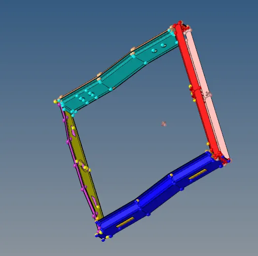
>Then given the assembly part,we going to creation of 1D connectors in different various connectors
>Relizing the connectors
STEP 1 :
>Firstly Given midsurface of all assembly parts ,generated 2D mesh
>Check the quality parameters of given values
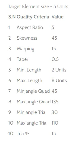
>Then Exact the mid surface of assembly part
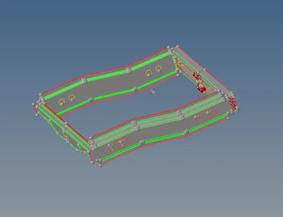
>After mid surface, go with automesh (f12) and mesh the component
>See the quality criteria values while doing the mesh
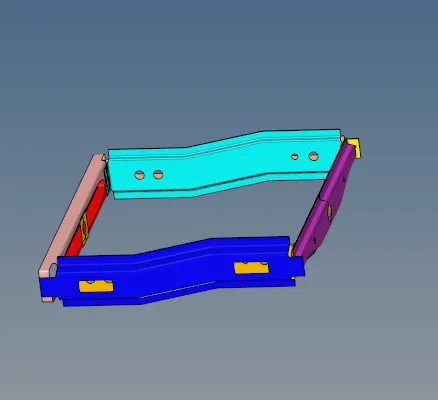
>Then Creation of 1D Connectors in different connectors
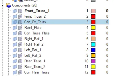
>Lets the creating different components,were as given of various components names are
> CREATING THE SEAM CONNECTOR:
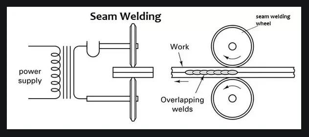
>SEAM CONNECTOR :
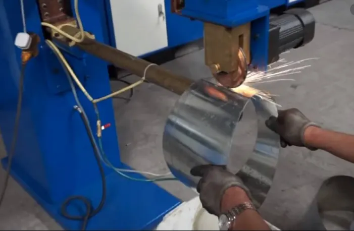
The process of joining the workpieces which is made of similar or dissimilar material along a continuous seam is known as seam weld
>Seam weld in hypermesh :
>Firstly taken the given component to weld of component
>While completing doing the mesh, the given required component is taken Right rail 2 and front truss
>Then go with 1D connectors,- connector-seam
>Select seam -spacing- tolerance- type - create
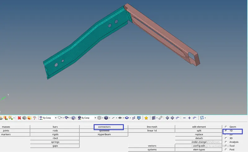

>Then created the seam-quad(angled+capped+L)
>The component of right rail 1 and front truss 1
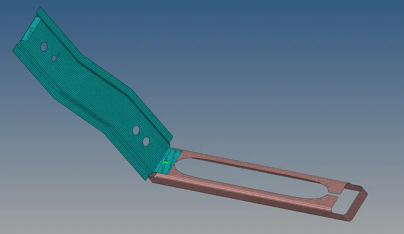
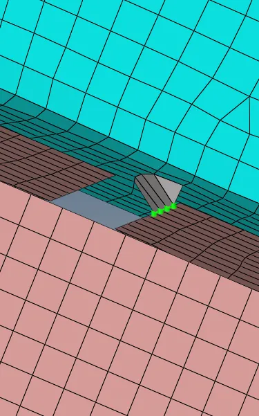
(a) The components while after creating seam weld (b) Here the clearly of seam weld component by two comopment
>Second part of component quad weld :

>Left rail 2 and front truss 1
>
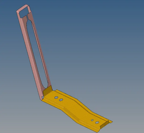
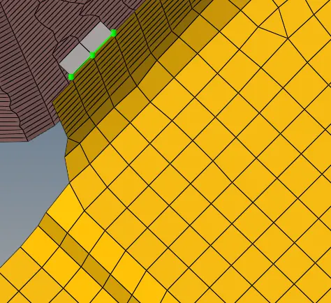
(a) The component of a while before creating the quad weld (b)clearly weld of quad weld
>THIRD PART SPOT WELD
>component front truss 2 and front 1 and right rail 1
>spot weld with 3 layers and 5 mm diameter

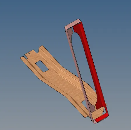
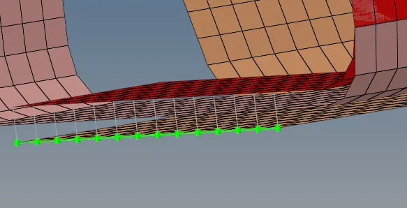
(a) Before creating the spot weld (b) After creating the spot weld bush type weld
>FOURTH CREATING THE HERA(ADHESIVE):


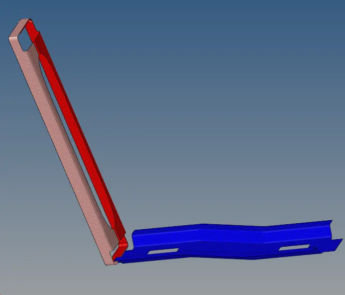
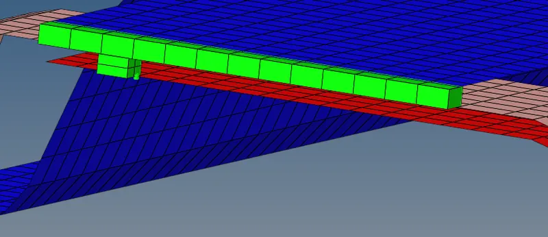
(a)Before creating the Hexa connector (b) created Hexa (adhesive) connector weld
FIFTH CREATING OF BOLT CONNECTOR
>

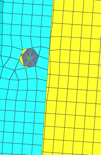
>we created a bolt weld connector
>select a node at a center of component
>select a component by two component
>Then click the create option
SIX CREATING A BOLT CONNECTOR

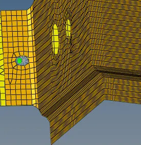
SEVENTH SPOT_WELD_WITH_RIGID ELEMENT
>

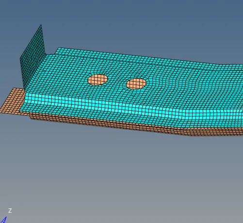
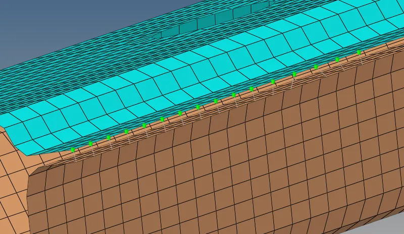
(a) Before the spot weld with rigid (b)After creating a spot weld with rigid element
EIGHT SPOT WELD WELD WITH SPRING ELEMENT


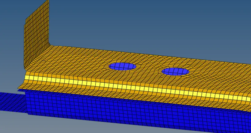
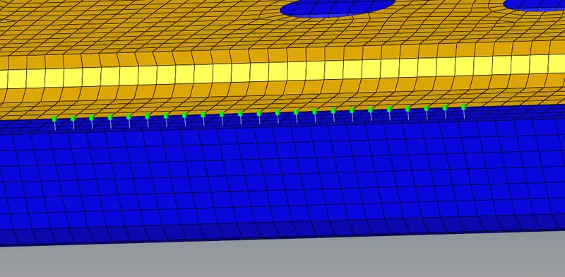
(a) Before the spot weld with spring element (b)After creating the spot weld with spring element
IMPORTANTANCE :
- CONNECTORS:
> Connectorsallow you to create relationship between two nodes in a FEA model when we discretize a complex CAD model
>The connections can be simple by using rigid or some of them will be weld or bolt connection ,which can impose the more complicated constraints
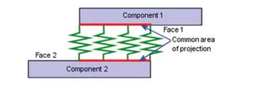
Here i using from example of connector with spring component face 1 and face 2
- CONNECTION BASICS :
>IN A FE - Model connection are basically used to join or assemble two or more parts together
>It can be mesh dependent or mesh independent
>Either contact or contactless
- MAJOR PROPERTIES OF THE CONNECTORS :
>Connector stiffness
>Force experienced by the connector
>Type of failure or mode of failure experience by the connector
- TYPES OF CONNECTORS PREFERRED
>1D Connectors :
>Simple representation and fast calculation
>Connection stiffness may not be an issue forcalculation
>2D connectors :
>Connection stiffness has to be considered
>accurate modelling of physical seenario
>To capture the connector deformation in modelling
>Mostly are welds , seam welds and bolt outer layer
- FINITE ELEMENT ENTITIES CONNECTORS REPRESENTATION :
>1D ----Rigid , bars,beams,spring etc.
>2D----Weld shell elements, bolts outerlayer elements etc
>3D----Solid bolt and nut representation ,are spot weld hexa
- STATES IN CONNECTORS RELIZATION :
>There are some representation of during connectors
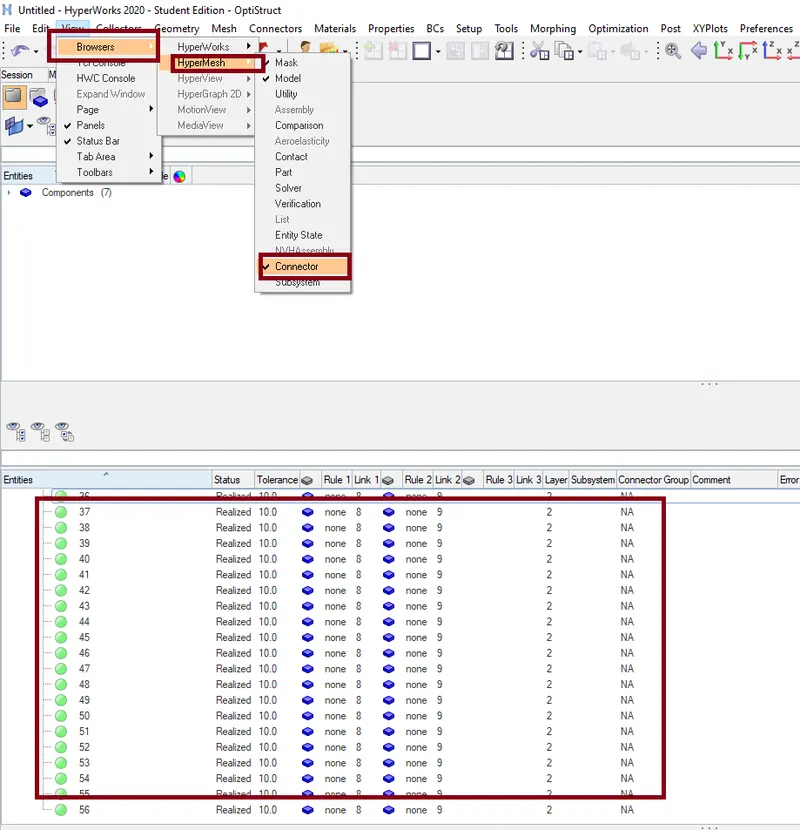
>YELLOW COLOUR -----"Unrealized connector"
>GREEN COLOUR ------"Realized successful creation"
>RED COLOUR -------"Which are failed to the connectors"
- BOLTS :
>A Bolt connection models a device that connects two compononebts,multiple components,or a component and the ground . it fixes these parts together
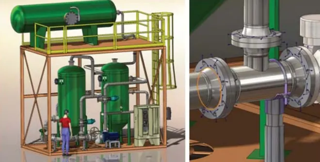
HERE i was using the example of a pipe route contain has many bolted fanges
- SPOT WELD :
>Spot welds can be used to join two very thin pieces of metal , they function best when the parts are less than 3mm thickness
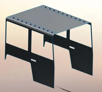
Spot weld in blue colour join the roof sides of a model a car
- REALIZING CONNECTORS can be done in a way :
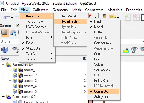
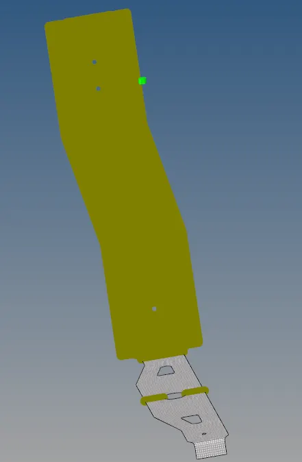
- IF ANY FAILURE OF WHILE DOING THE 1D CONNECTORS >Once check free edges ,and find out clear it by the equivalance option >And once check the duplicated elements
- VEIW THE CONNECTOR IN HYPERMESH THEN SEE DIFFERENCE OF FAILED AND RELIZED :
- TOLERENCE : The gap of difference between min size and maximum size
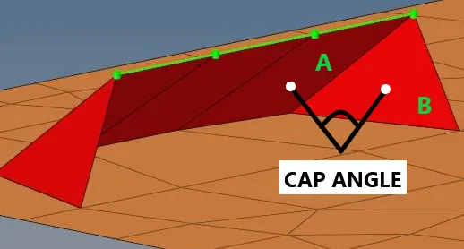
>CAP ANGLE : Angle between the normal of the first slant weld element and in adjacent side element
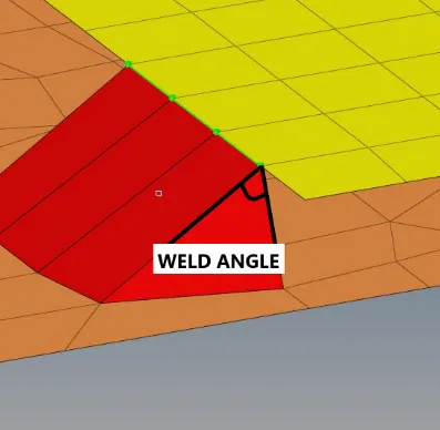
>WELD ANGLE : Angle between the normal projection of the nodes and slant length of the weld element it is recommended to define weld angle between 0 and 90 degree
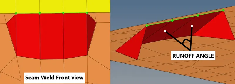
>RUNOFF ANGLE : Angle between the normal of the first slant weld element and its weld adjacent weld element
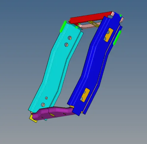
FINALLY CONNECTORS WITH ASSEMBLY PART :
UNDESTAND BY THIS TOPIC
>How to created of 1D connectors, seam,bolt, Hexa,spring ,etc
>How to Realizing and non-realizing error
>What is the Weld Eagle,runoff angle,cap angle differences
CONCLUSION :
>Finally created the 1D connectors of different components and different welds