Assignment 5-RADIOSS Interfaces & Study of Effect of Notches Challenge
OBJECTIVE :
- Run the crash tube model as it is.
- Change the Inacti=6 and run.
- Create the type 11 contact and run.
- Remove both notches and remove boundary condition on rigid body node then run.
- Create a new notch in the middle ,select the whole section and run.
- Create a new notch with nodes only from opposing 2 faces and run.
>INTERFACE: Interfaces are defined to model how parts interact when they come into contact with each other
Aim :Create the mesh for bumper assembly AND geometry clean up
>procedure :
>firstly import the model bumper
>After geometry clean up
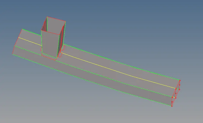
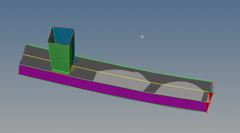
>genareting the mesh on the bumper :
>Element size as given 6mm

CASE 1 : Run the crash tube model as it is.
>PROCEDURE :
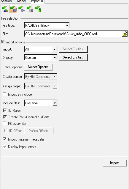
>Firstly im[port the given rad.file crash tube
>Then go with same of tjhe run the simulation in radioss
>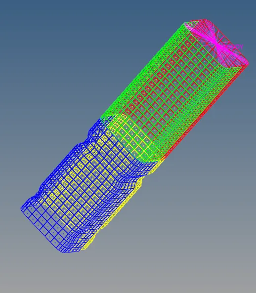
>Then in visible in shaded element and mesh line format
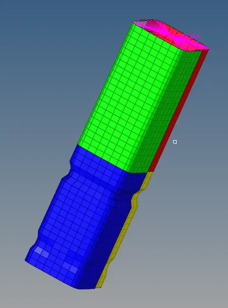
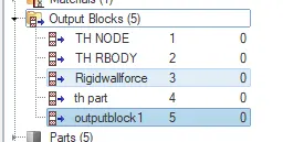
>Creating Th part :
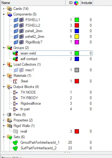
>The model consists of components parts :
>
> Next step we have run simulation that we needed of analysis-radioss panel

>After intering the radioss panel, then input the file given of 0.0000rad file initially , run option same ausally analysis, run number as put 1 , main important steps in the option as put the value of (-nt 4) , it means of assigning the task of 4 times of run the perform the simulation faster, it depends of our computer processor
>Next the open of 0.0001 rad file in the notepad which are obtained of no of cycles and we know of seen in maximum output results were of energy errors
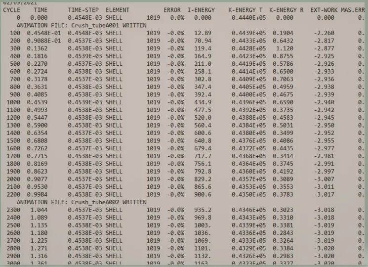
>Now open the animation file obtained :
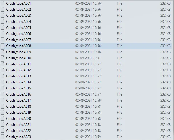
>The performing of simulation were of last cycle energy errors are obtainted of :
>Energy error = -3.8%
>Internal energy = 0.2455E-03
>Kinetic energy = 592.7
>External work =0.2177-105.2
>Mass error = 0
>Total number of cycle =82500
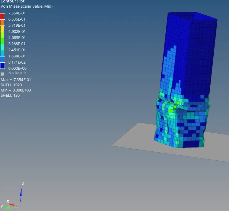
>Then go with contour option :

>After clicking of contur were visible of :

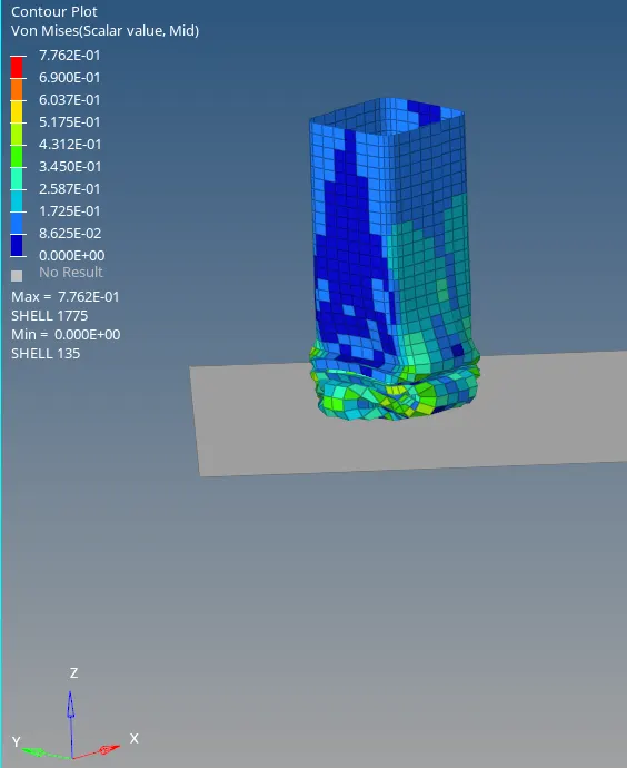
>And value of von mises(s) maximum stress and of minimum stress value were obtained result see in below animation
>POST PROCESSING :
>To perform the post processing we have necessary to hygraph 2D panel to obtained of various graph plot results.
>The first graph to obtain the rigid wall forces, this done by the switch on the hyper graph 2D panel
>Then import the T01(TIME HISTORY)file
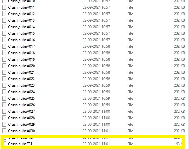
>Then follow of main step unit system, while i was giving the solver option,it will give some of the recommended unit of solver indirectly ,if we want to give a particularly and clearly whole of unit wise we should be in perfect, otherwise it will go inaccurate results of plots

>
>The plot of graph rigid wall force :
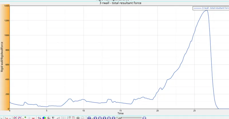
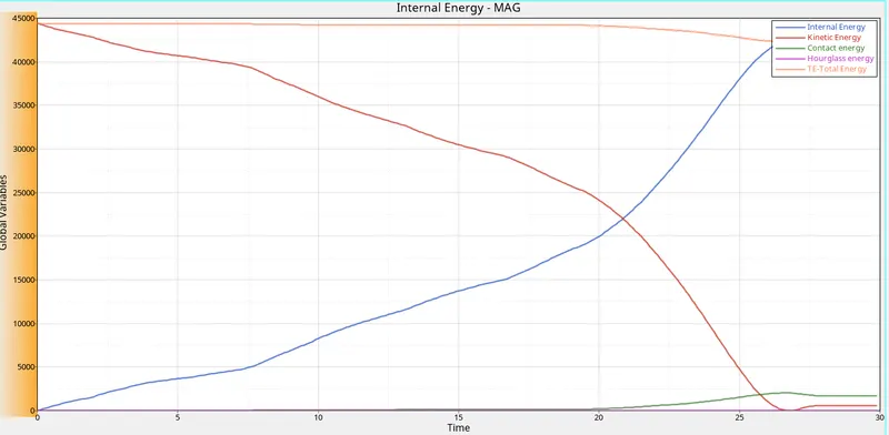
>The next plot of energy error of results obtained wish off internal energy, kinetic energy, total energy, contact energy and hourglass energy
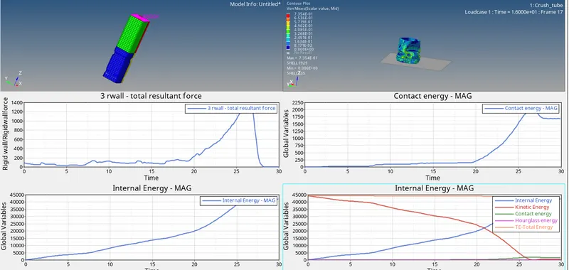
>AS the graph of combined of all views :
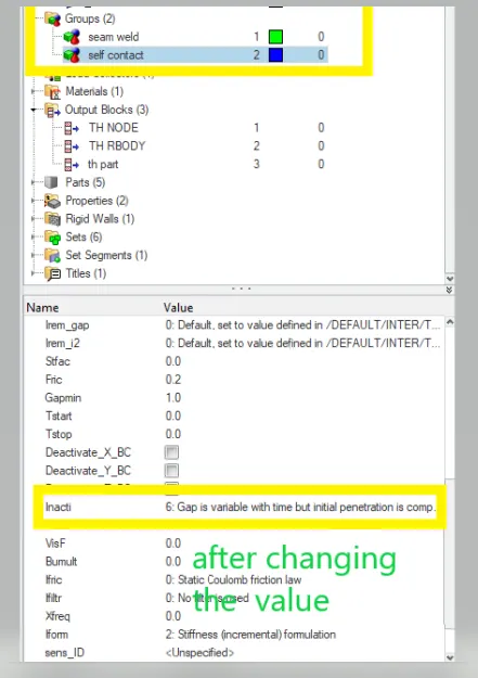
CASE 2 : Change the Inacti=6 and run
>Then we have to change the value and run the simulation result
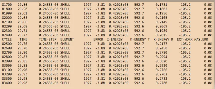
>Next the open of 0.0001 rad file in the notepad which are obtained of no of cycles and we know of seen in maximum output results were of energy errors
>Now open the animation file obtained :
>The performing of simulation were of last cycle energy errors are obtainted of :
>Energy error = -3.8%
>Internal energy = 0.4202E+05
>Kinetic energy = 592.6
>External work =0.2455E-03
>Mass error = 0
>Total number of cycle =83400
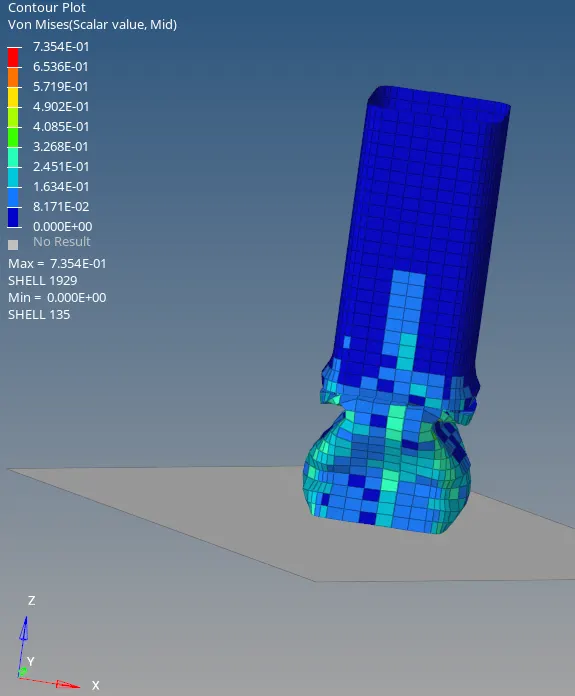
>And value of von mises(s) maximum stress and of minimum stress value were obtained result see in below animation
>POST PROCESSING :
>To perform the post processing we have necessary to hygraph 2D panel to obtained of various graph plot results.
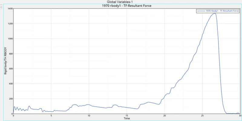
>The first graph to obtain the rigid wall forces, this done by the switch on the hyper graph 2D panel
>Then import the T01(TIME HISTORY)file
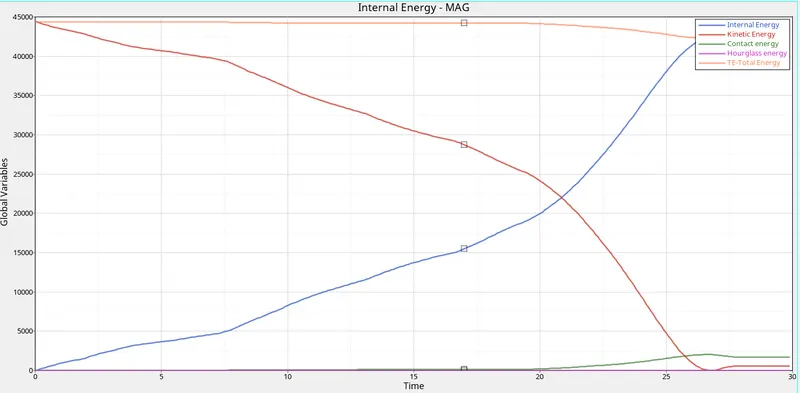
>The next plot of energy error of results obtained wish off internal energy, kinetic energy, total energy, contact energy and hourglass energy
>The plot of graph rigid wall force :
>AS the graph of combined of all views :
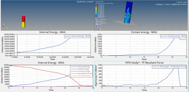
CASE 3 : Create the type 11 contact and run.(EDGE TO EDGE )
>firstly we create the type 11 (edge to edge) and change the recommended values to obtain the better result
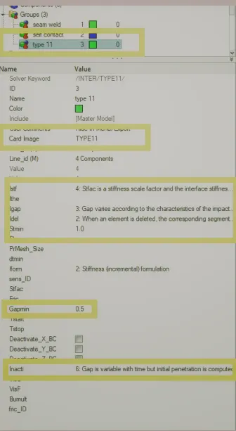
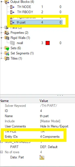
>And make create of function in the output block and assigned which are we required
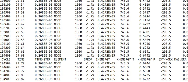
>Next the open of 0.0001 rad file in the notepad which are obtained of no of cycles and we know of seen in maximum output results were of energy errors
>Now open the animation file obtained :
>The performing of simulation were of last cycle energy errors are obtainted of :
>Energy error = -3.8%
>Internal energy = 0.4277E+05
>Kinetic energy = 743.6
>External work =-200.5
>Mass error = 0
>Total number of cycle =184900
>And value of von mises(s) maximum stress and of minimum stress value were obtained result see in below animation
>POST PROCESSING :
>To perform the post processing we have necessary to hygraph 2D panel to obtained of various graph plot results.
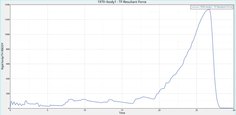
>The first graph to obtain the rigid wall forces, this done by the switch on the hyper graph 2D panel
>Then import the T01(TIME HISTORY)file
>The next plot of energy error of results obtained wish off internal energy, kinetic energy, total energy, contact energy and hourglass energy
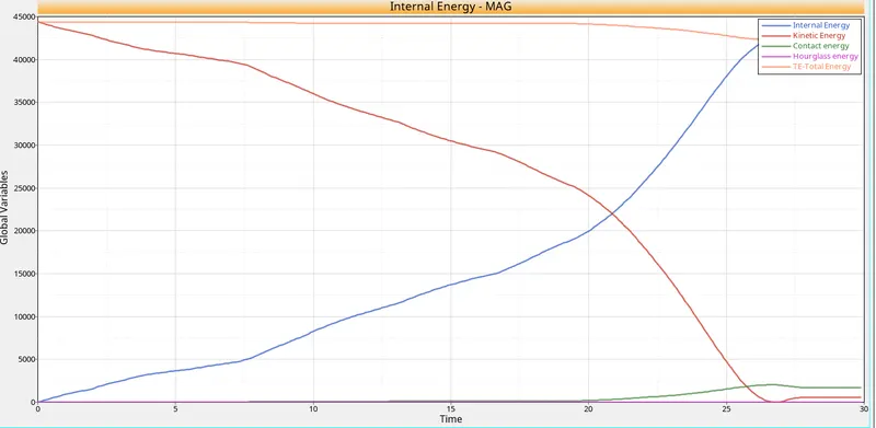
>The plot of graph rigid wall force :
CASE 4 : Remove both notches and remove boundary condition on rigid body node then run.
>NOTCHES: an indentation or incision on an edge or surface.
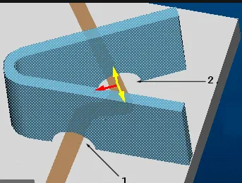
>step of removing the notches by using F7 option align nodes and then align the nodes to nodes
>Before editing the notches
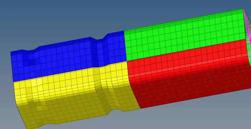
>After making changes of notches on the rigid body
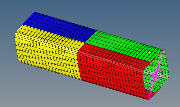
>Now we deleting the boundary condition and running the simulation
>BCS ARE were of the degree of freedom as rotational and transitional
>Before deleting the BCS
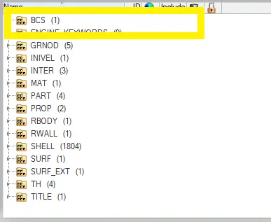
>AFTER removing the boundary condition
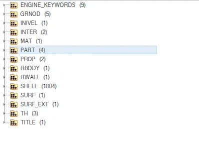
>Next the open of 0.0001 rad file in the notepad which are obtained of no of cycles and we know of seen in maximum output results were of energy errors
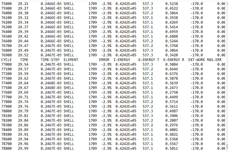
>Now open the animation file obtained :
>The performing of simulation were of last cycle energy errors are obtainted of :
>Energy error = -2.9%
>Internal energy = 0.4242E+05
>Kinetic energy = 537.1
>External work =-170.0
>Mass error = 0
>Total number of cycle =78800
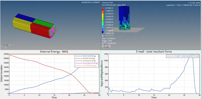
>And value of von mises(s) maximum stress and of minimum stress value were obtained result see in below animation
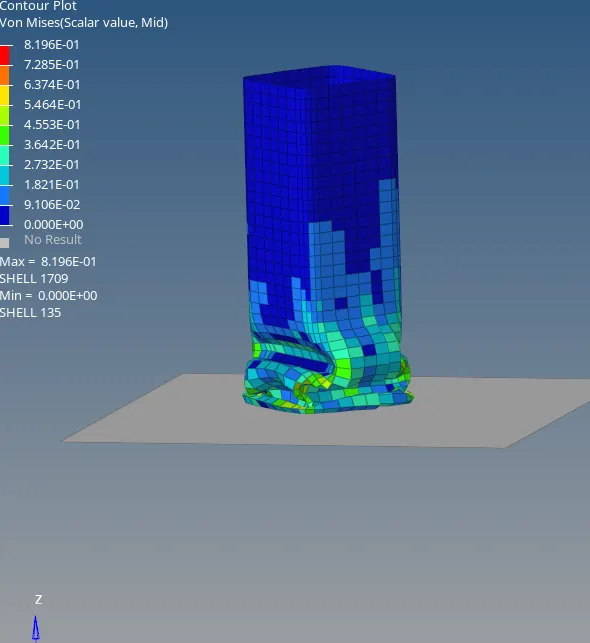
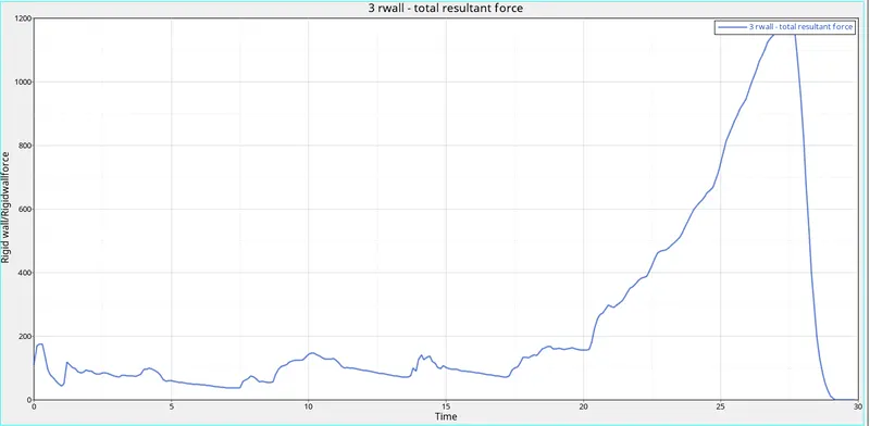
>POST PROCESSING :
>The next plot of energy error of results obtained wish off internal energy, kinetic energy, total energy, contact energy and hourglass energy
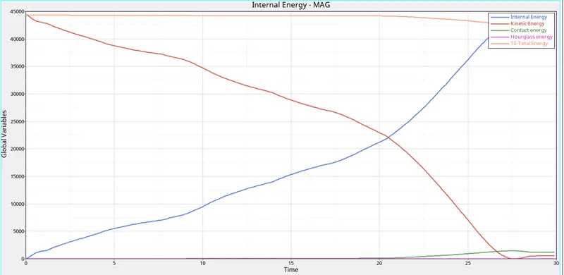
>The plot of graph rigid wall force :
>AS the graph of combined of all views :
CASE 5: Create a new notch in the middle, select the whole section and run.
>Now create the notch at the middle on the rigid body
>Before creating the notch at the middle on the rigid body
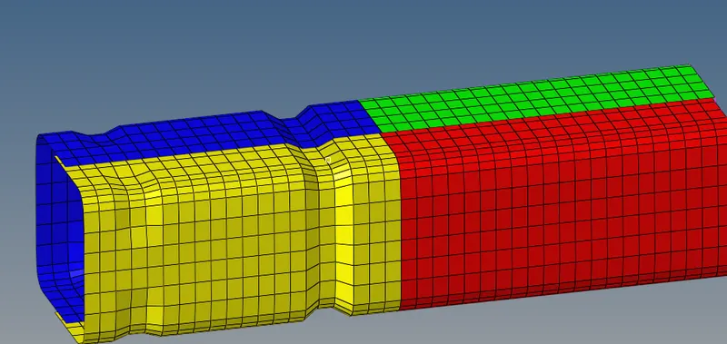
>After creating the notch at the middle
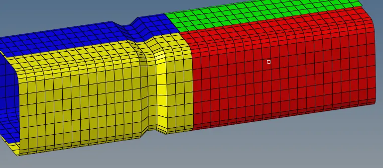
>Next the open of 0.0001 rad file in the notepad which are obtained of no of cycles and we know of seen in maximum output results were of energy errors
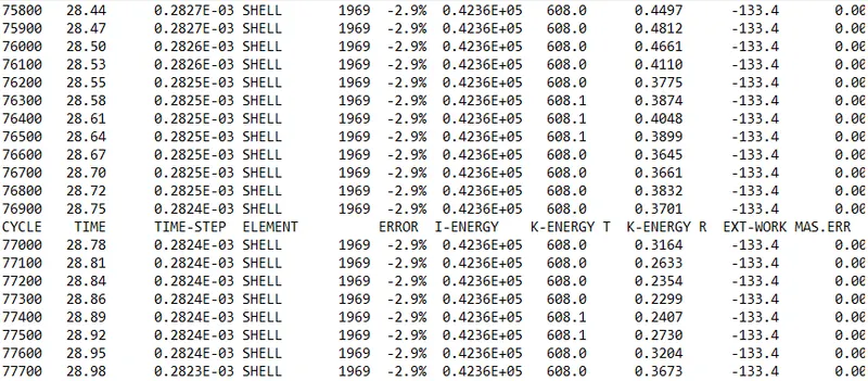
>Now open the animation file obtained :

>The performing of simulation were of last cycle energy errors are obtainted of :
>Energy error = -2.9%
>Internal energy = 0.2823E-03
>Kinetic energy = 608.0
>External work =-133.4
>Mass error = 0
>Total number of cycle =77700
>And value of von mises(s) maximum stress and of minimum stress value were obtained result see in below animation
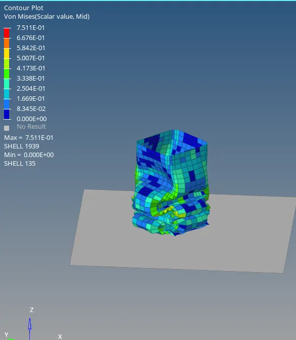
>POST PROCESSING :
>The next plot of energy error of results obtained wish off internal energy, kinetic energy, total energy, contact energy and hourglass energy
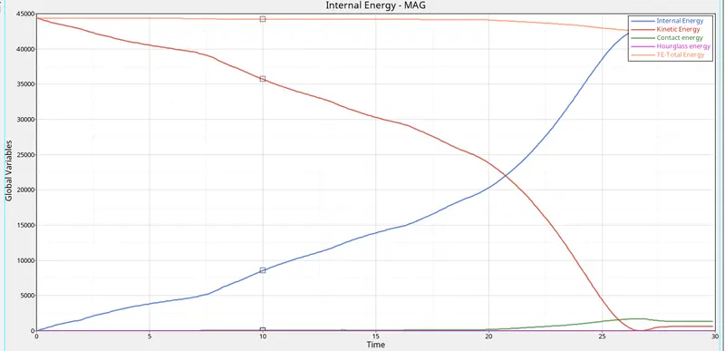
>The plot of graph rigid wall force :
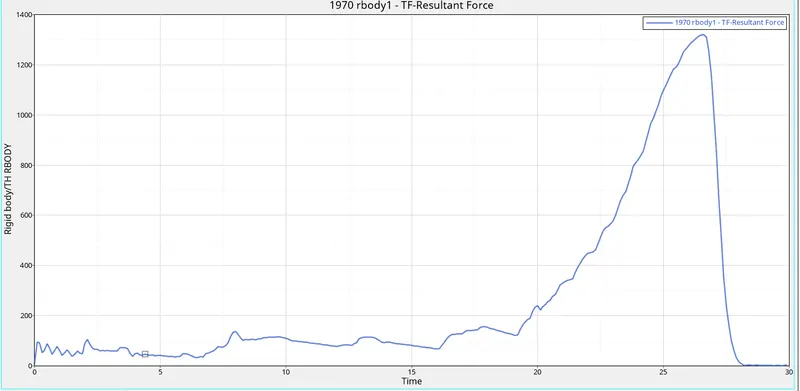
>AS the graph of combined of all views :
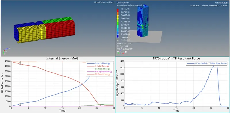
CASE 6 : Create a new notch with nodes only from opposing 2 faces and run
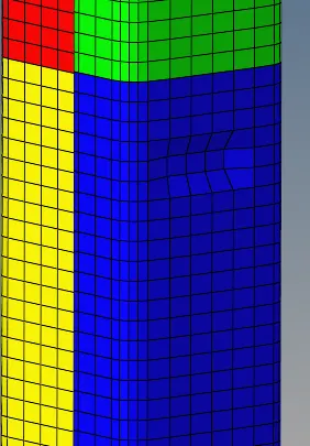
>Firstly we create an opposite notch on the rigid body
>After creating the notch on the opposite
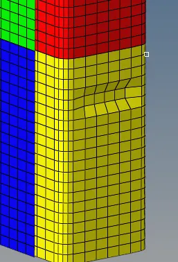
>An another side
>Next the open of 0.0001 rad file in the notepad which are obtained of no of cycles and we know of seen in maximum output results were of energy errors
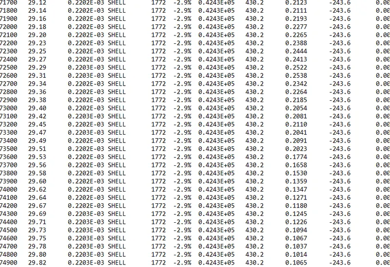
>Now open the animation file obtained :
>The performing of simulation were of last cycle energy errors are obtainted of :
>Energy error = -2.9%
>Internal energy = 0.22033E-03
>Kinetic energy = 0.4243E+05
>External work =-243.6
>Mass error = 0
>Total number of cycle =74900
>And value of von mises(s) maximum stress and of minimum stress value were obtained result see in below animation
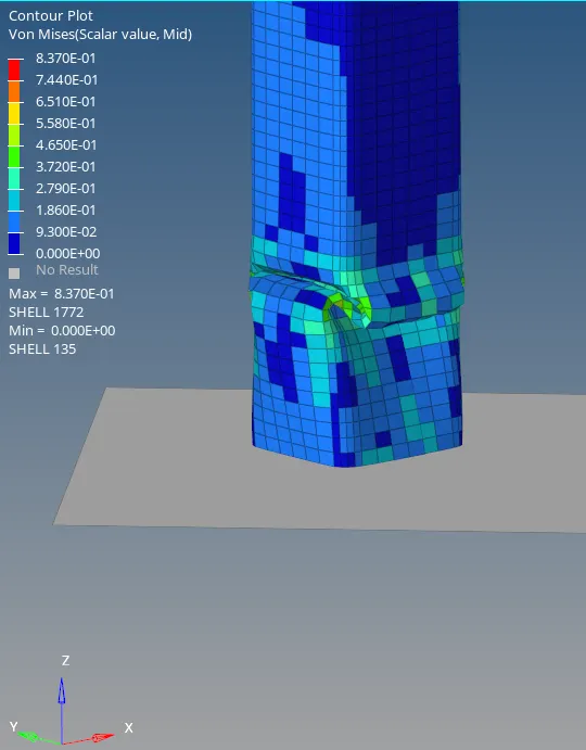
>POST PROCESSING :
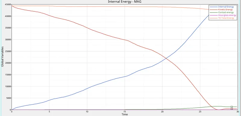
>The next plot of energy error of results obtained wish off internal energy, kinetic energy, total energy, contact energy and hourglass energy
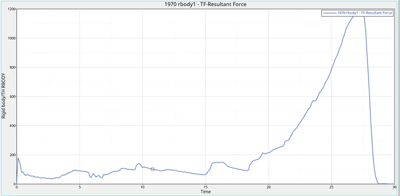
>The plot of graph rigid wall force :
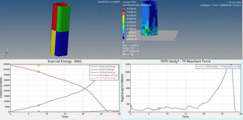
>AS the graph of combined of all views :
>The differences of various cases are :
>Case 1 : As the crash on the rigid wall the forces as the impact of one side of the rigid body were of kinematic energy as decreases and internal energy increasing and hourglass is contact
>Case 2 : The penetration is going the inside of the master node its pulled to slave node then the energy mass as required so there are some of the energy changes so we required that type 7 and some of changes value were of inacti take of 6 and some various changes in the internal and kinematics energy
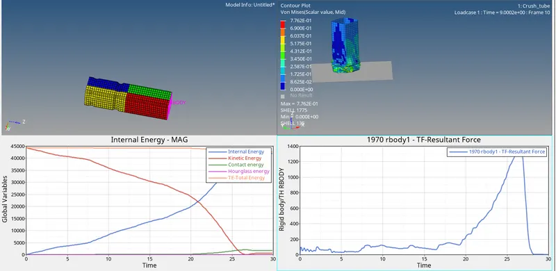
>Case 3 : In the case 3 we have take of type 11 only from edges to edges it does not allow of the node to surface its acceptable only contracting the edge to edge and seen in the rigid wall forces at last some varies of changing increasing and after crash its going totally decreases and also in global energy
>Case 4 : while removing notches and boundary conditions at a point of compressed starts then its collapse of suddenly because there don't have to absorb shock at a time and it will take less time because of the absence of the notch on the rigid body and were mass-energy also zero and changes in the internal energy
>Case 5 : In the case 5 in the middle of the notch on the rigid body thereof absorb energy at the notches on the body and also changes of energy while comparing of previous cases
>Case 6 : The opposite face of notches on the rigid body is compressed there were of energy consumed more and several changes in the energy and the rigid wall forces and mass-energy is still zero
>COmparising of all cases
| s.no | Notches | kinematic energy | Internal energy | Mass error | Max-von mises | External work |
| case 1 | Notches will be there | 0.277-105.2 | 0.2455E-0.3 | 0 | 7.354E-01 | 592.7 |
| case 2 | Notches will be there | 592.6 | 0.4202E+05 | 0 | 7.354E-01 | 0.2455E-03 |
| case 3 | Notches will be there | 743.6 | 0.4277E+05 | 0 | 7.7762E-01 | 200.5 |
| case 4 | Not | 537.1 | 0.4242E+05 | 0 | 8.196E-01 | -170.0 |
| case 5 | Notches will on the middle | 608.0 | 0.2823E-03 | 0 | 7.511E-01 | -133.4 |
| case 6 | Notches on opposite faces | 542.6 | 0.22033E-03 | 0 | 8.307E-01 | -243.6 |
>Learing outputs :
>obsevation in various results with respect in the changes of notches
>obseving the behavior crashes by various cases
>Undestand with notches and without notches crashes on the rigid wall
>Observed in the changing global energy and rigid wall forces
>CONCULSION :
>Generated mesh on the given bumper component
>changed of parameters of values in all cases for the given crash tube
>Finally completed of plots and rigid wall forces and animation files and compared of the all result