Week-6 Challenge: EV Drivetrain
AIM:EV Drivetrain
1. Which types of power converter circuits are employed in electric and hybrid electric vehicle?
- AC to DC converters are most commonly used in Plug-in Hybrid Electric Vehicles (PHEV) & Plug-in Electric Vehicles (PEV)
- DC-DC converters can be used to interface the elements in the electric power train by boosting or chopping the voltage levels
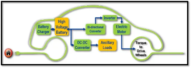
- There are five main types of converter in this non-isolated group, usually called the buck, boost, buck-boost, Cuk and charge-pump converters. The buck converter is used for voltage step-down, while the boost converter is used for voltage step-up.
- Moreover, a DC- DC converter is a critical component in the architecture of a BEV, where it is used to convert power from the high voltage (HV) bus to the 12V Low Voltage (LV) bus to charge the LV battery and power the onboard electric devices.
- Advantages of DC Converter
Battery space can be reduced by reducing or increasing the available input voltage. A device can be driven by bucking or boosting the available voltage.
2. An Electric Vehicle's powertrain with 72V battery pack in shown in the diagram below. The duty ratio for acceleration operation is 'd1' and for the braking operation the duty ratio is 'd2'.
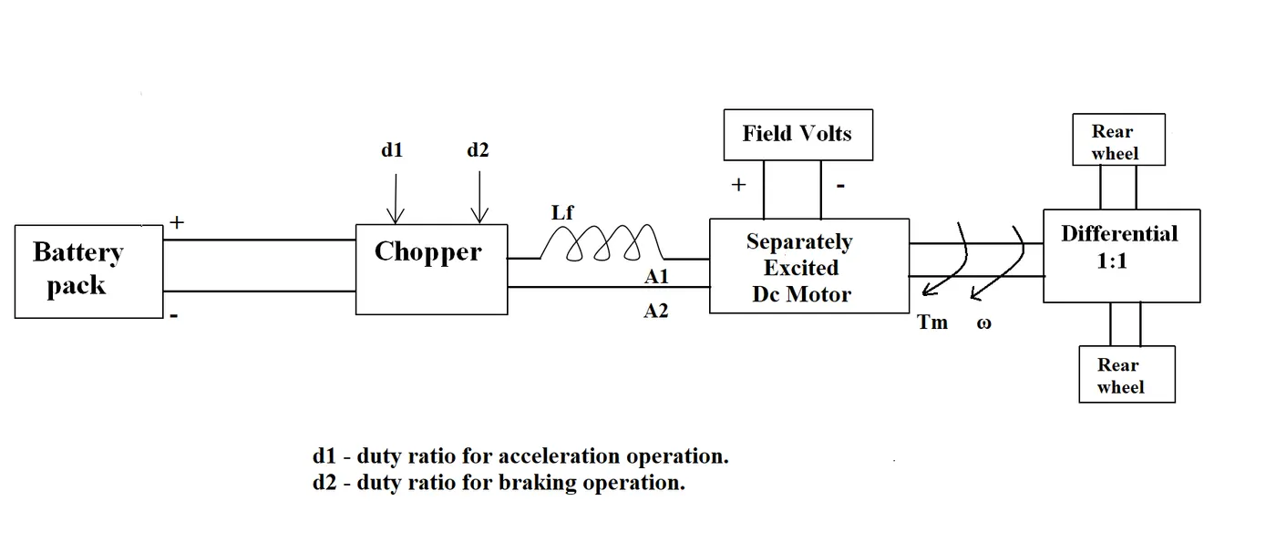
The other parameters of the electric vehicle is given below,
Motor and Controller Parameters:
Rated Armature voltage= 72 V
Rated armature current= 400 A
Ra= 0.5Ω, KΦ= 0.7 Volt second
Chopper Switching frequency= 400 Hz
The vehicle speed-torque characteristics are given by the below equation

T = v.K/r-K62.w/r
BY COMPARING TWO EQ:
What is EV steady state speed if duty cycle is 70%?
ans) electric vehicle is given below
Motor and Controller Parameters:
Rated Armature voltage= 72 V
Rated armature current= 400 A
Ra= 0.5Ω, KΦ= 0.7 Volt second
Chopper Switching frequency= 400 Hz
ω= V/Kϕ -Ra/Kϕ^2 .T
T= Kϕ*V/Ra - Kϕ^2*ω/Ra
voltage after 70 %duty ratio = 72*70
V = 50.4
BY COMPARING TWO EQ:
24.7+0.0051*W^2=(V*k/r)-(K^2)*W/R)
24.7+0.0051*W^2=(72*0.7*0.7)/0.5-(0.7^2/0.5)*W=24.7+0.0051*W^2
70.56-0.98*W=24.7+0.0051*W^2
W^2+192.15*W=24.7+0.0051*W^2
W^2+192.15*w-8999.15=0
In order to find the roots use formula

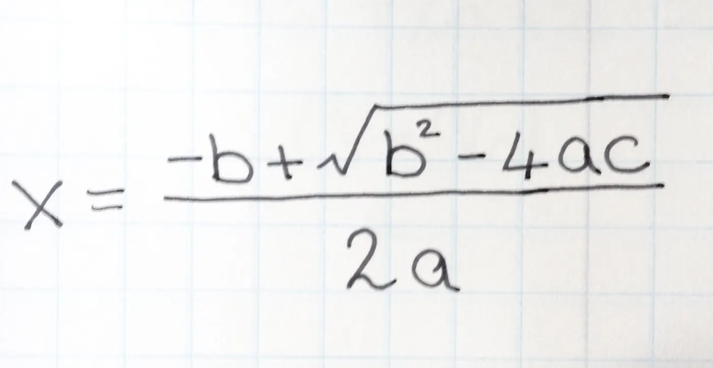
so then w=38.95rad/sec
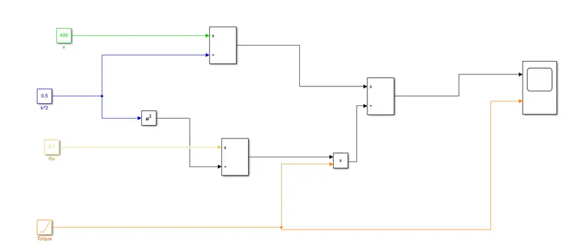
3. Develop a mathematical model of a DC Motor for the below equation using Simulink.
ωω= V/Kϕϕ -Ra/Kϕϕ^2 .T
>MODEL
4. Induction Versus DC brushless motors by Wally Rippel, Tesla
In the blog of induction and DC brushless motor, the author has mentioned about positives and negative side of both the induction and DC motor. In the blog, the basic construction of both the induction and DC brushless motor is explained.
One of the main differences is that much less rotor heat is generated with the DC brushless drive. Rotor cooling is easier and peak point efficiency is generally higher for this drive. It is mentioned that the DC brushless can drive at unit power factor, whereas the best power factor for the induction drive is about 85%.
Whereas in case of induction motor, the current is supplied to the stator which results in the generation of emf, when this emf comes in contact with the rotor which is generally a squirrel cage type, this results in current induced in the rotor. Unlike the DC motor, the rotor consists of conductors plates and placed in a cage-like structure. This also consists of bars around them in which current get induced and the rotor starts rotating.
In case of DC brushless motor, the strength of the magnetic field is adjustable. When at low speed the maximum torque is required magnetic field should be maximum, i.e. inverter and motor current maintained at their lowest optimize efficiency. Whereas there is no such adjustment in case of induction motor.
The construction of DC brushless motor is costly compared with an induction motor, due to the use of permanent magnets.
>OUTPUT OBSERVATION:
Types of converters used in HEV and EV vehicles.
The Brushless DC motor is used for Hybrid and Plug in hybrid vehicle. While the induction motor is used for pure electric vehicle.