2D Meshing using hypermesh
Objective:
To mesh the given three components such as practice component, clip repair, mounting repair by using given quality criteria after the geometry cleanup and midsurface generation and assign thickness after meshing.
| s.no | Quality criteria | value |
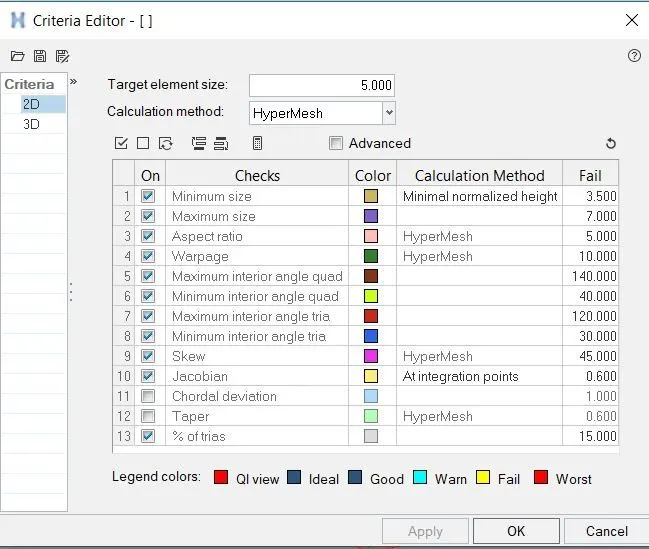
| 1 | min length | 3.5 |
| 2 | max length | 7 |
| 3 | target length | 5 |
Procedure:
Model images:
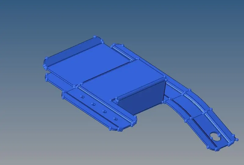
Practice model
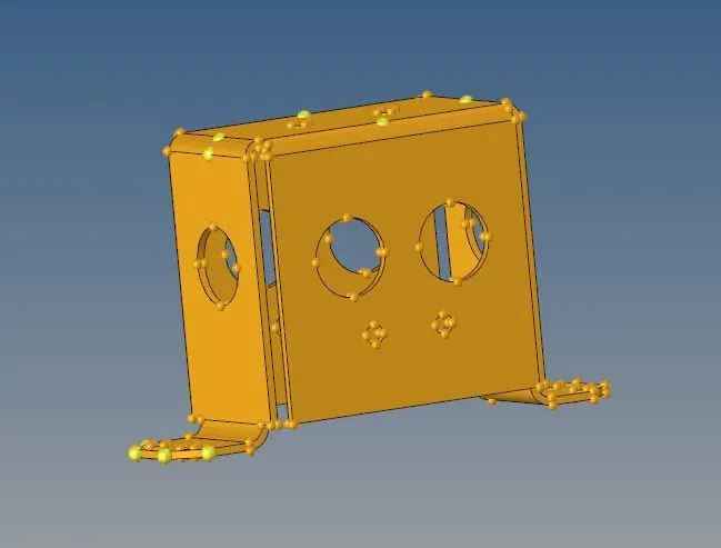
clip repair
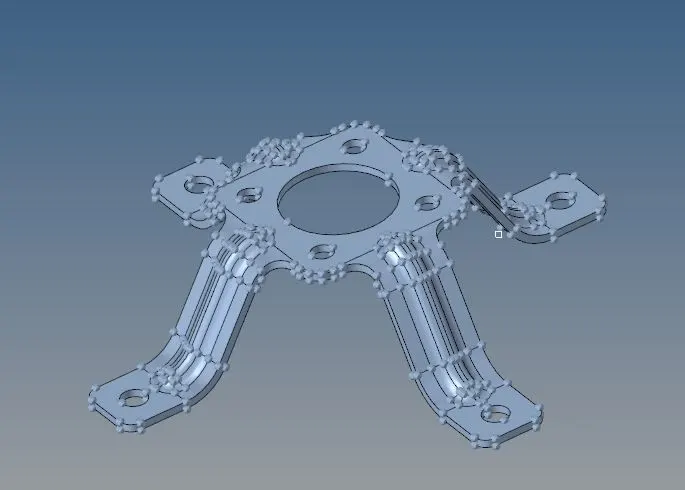
mounting bracket
1. Import the geometry in hypermesh using Radioss solver. After that switch to topo mode for check the geometry errors. Delete the solids in the geometry using delete>solids tool.We need to clear the free edges in the geometry for take auto midsurface in next step.
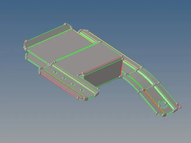
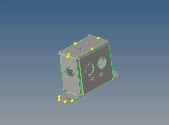
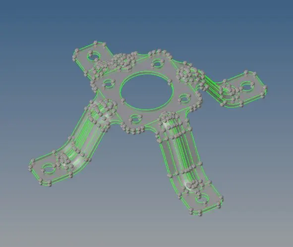
2. Here we have some free edges if the surface is missed out in the geometry. fill the surface by using geometry>quick edit>filler surf.
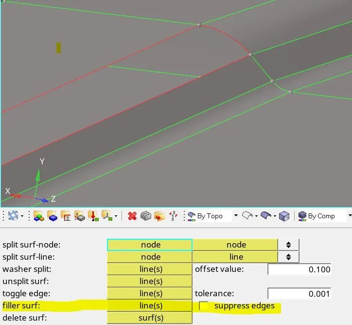
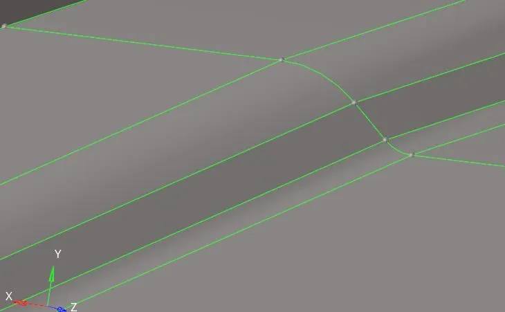
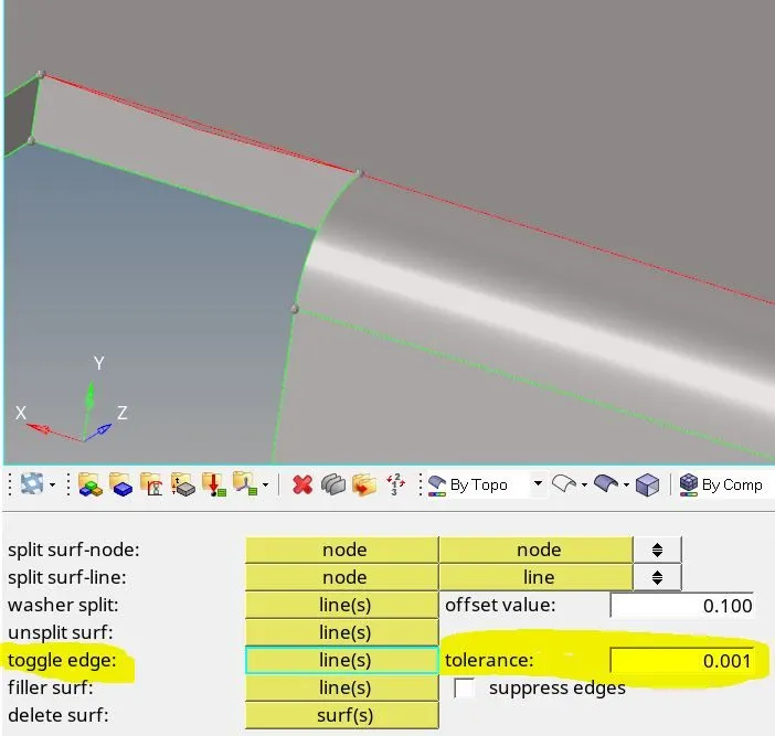
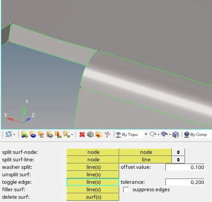
3. Another case we have some free edge lines in the geometry. we can toggle the lines by using geometry>quick edit>toggle and give the tolerance value higher when it doesn't toggle.
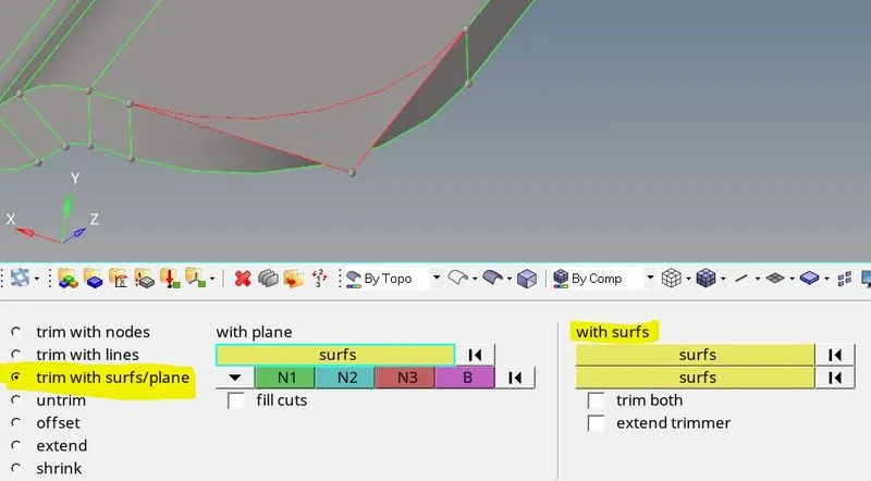
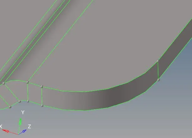
4. Here we have some issues like two surfaces are intersect each other. we have to delete the extend surface by using geometry>surface edit> trim with surfaces.
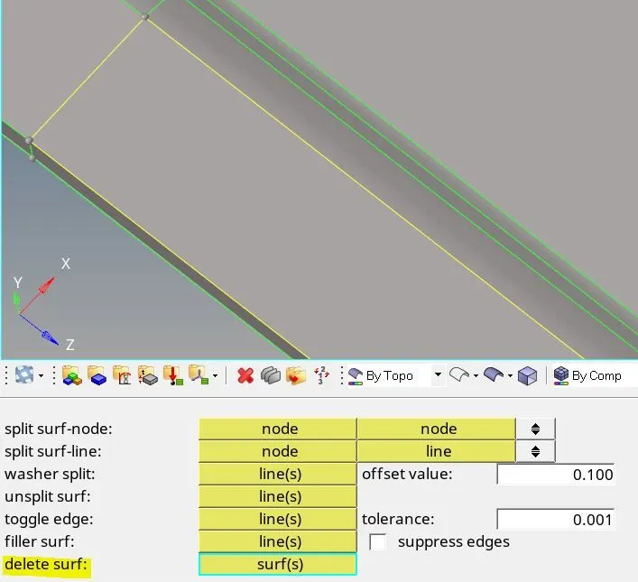
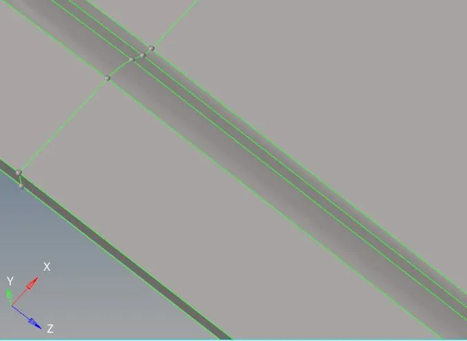
5. Now we have some duplicate surfaces connected each other. we need to delete the surface by using geometry>quick edit>delete surf.
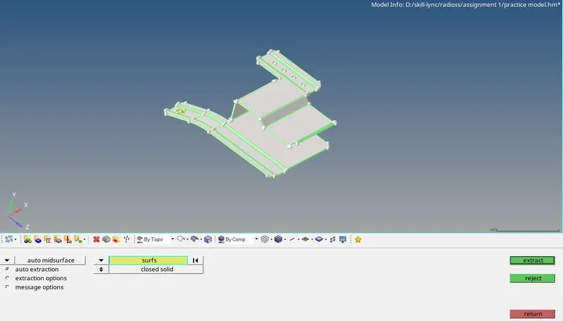
6. After geometry cleanup, we need take midsurface for the geometry. We have two methods to generate mid surface. first one by selecting geometry>midsurface either selecting geometry>surface edit>offset. Here we have use a tool called midsurface by clicking geometry>midsurface>auto (for auto midsurface we need a closed solid). Select the geometry and click extract. the mid surface will be generated.
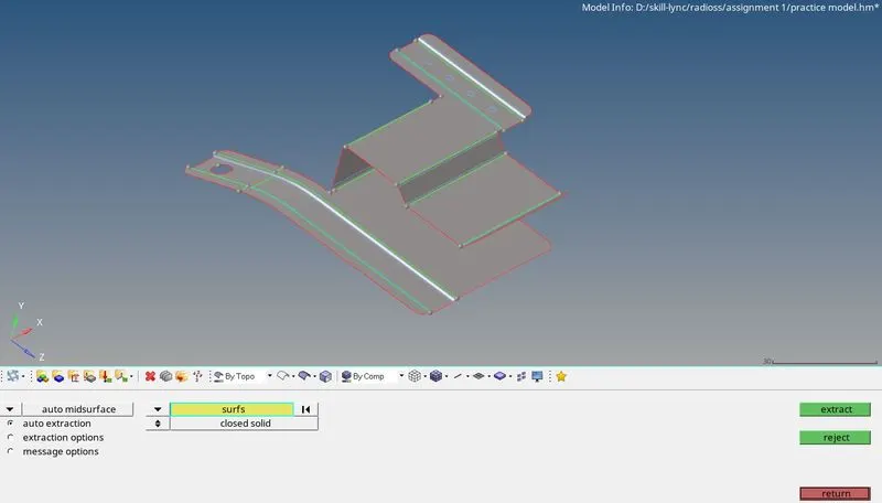
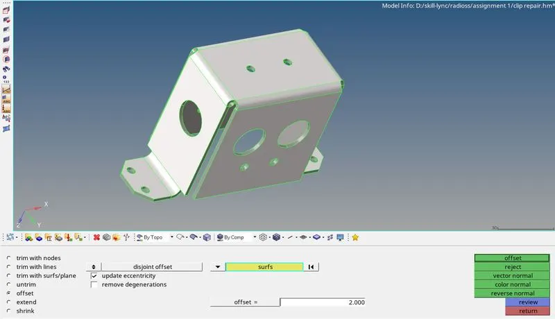
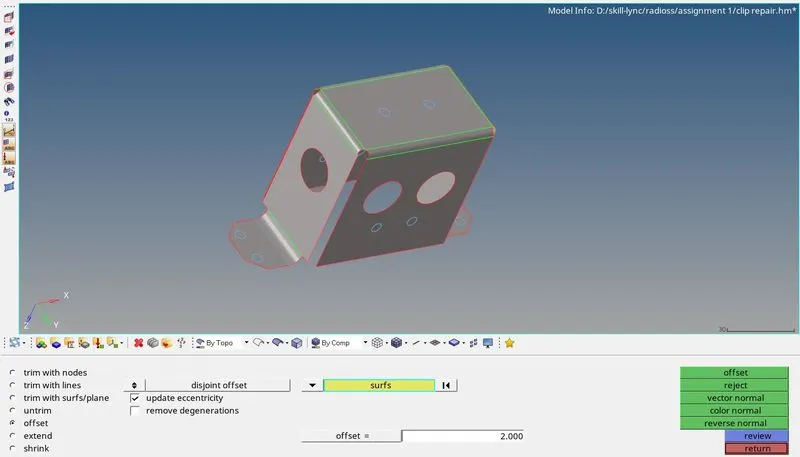
7. Here we have another model. we should use offset tool for generate mid surface by selecting geometry>surface edit>offset. Before select the surfaces for offset we should create a new component collector and make as current component. now select the surface and right click the tab and select by face option. now all the surfaces are selected not a entire component. now right click the tab, select duplicate for offset surface and select current component. Before clicking offset check the offset normal if it is negative select reverse normal option to reorient the surfaces. now select the offset tool. the midsurface is generated for the selected component.
8. After midsurface generation, we can do the mesh over the midsurfaces of the components. Before go for meshing, we need prepare the geometry for meshing by toggling some lines to avoid minimum element fail. cut some areas for good mesh flow. Replace or attatch some points to avoid minimum element fail.
We can toggle the lines where the elements were failed for minimum length by selecting geometry>quick edit>toggle.
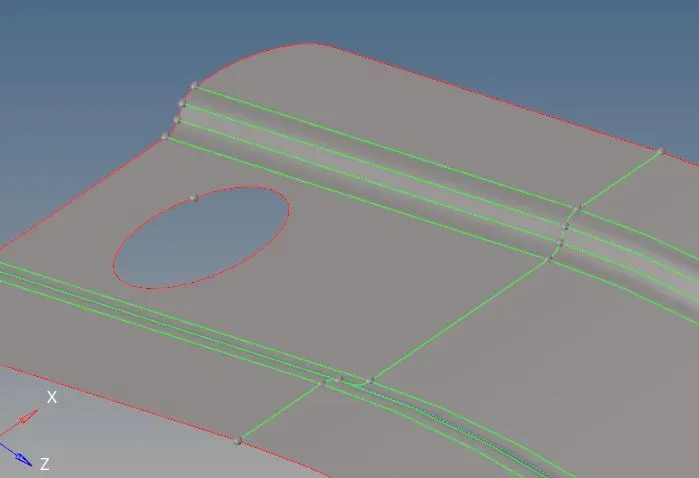
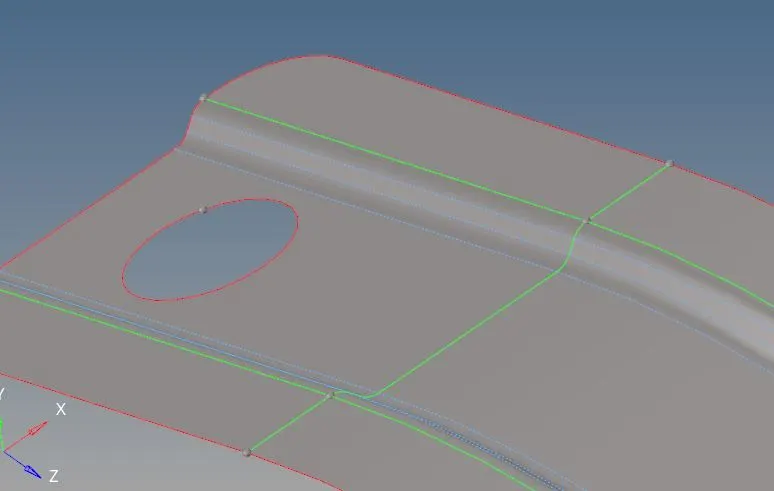
Here we have to make some cuts over the surfaces for getting good mesh flow by selecting geometry>quick edit>split surf-line.
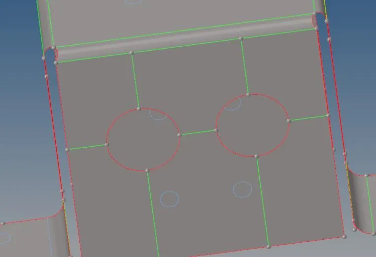
We need to replace and attach some points to get the good mesh flow by selecting geometry>quick edit>replace point.
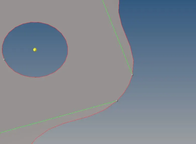
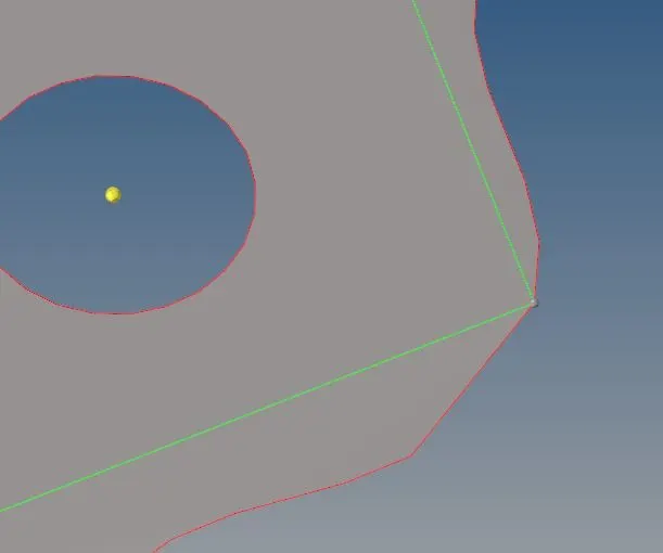 .
.
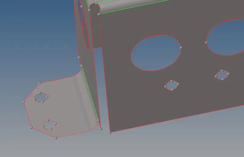
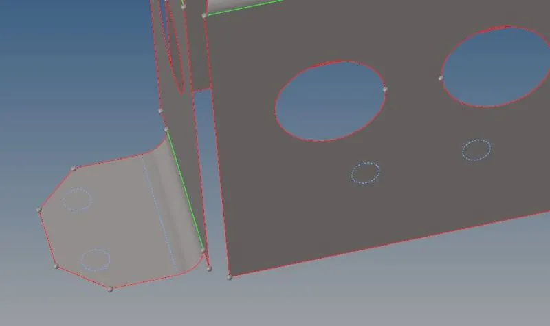
9. As per the given statement, we can ignore the holes less than 5mm diameter. we should fill the holes and toggle lines by selecting geometry>quick edit>filler surf and geometry>quick edit>toggle.
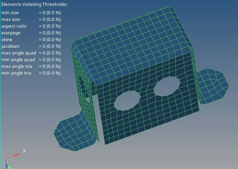
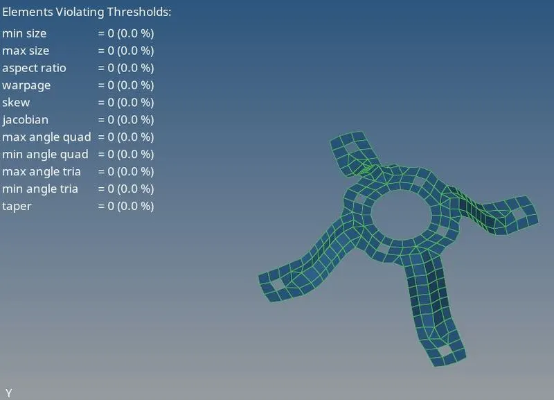
10.After prepare the geometry, now we can do the mesh over the surfaces. At first We should assign the quality criteria for the geometry. This is done via Preferences>criteria file settings. Assign the values given in the objective. We can give some value to get a good mesh as per the requirement.
10. Now we can start the mesh for the component one by one. We should select 2D>Automesh. After selecting the tool, assign target element length as 5mm. assign element type as mixed. select the surface one by one.

11. After the mesh is created. We should clean the mesh for reduce trias and clean the element failures. we can use various tool for this. select 2D>quality index and now swap edge for swapping the edge and drag tria tool for drag the trias to clear the trias. Element optimize tool used for optimize the element from element fail. smooth tool is used to smooth the mesh.
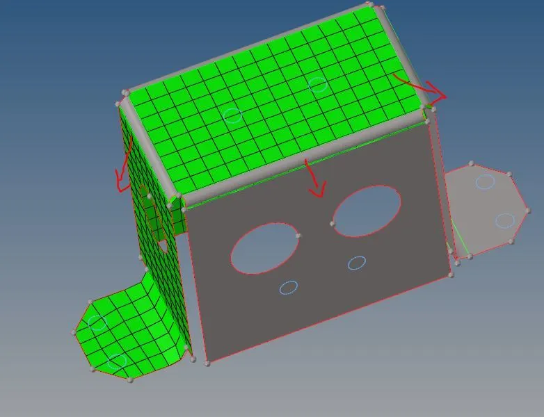
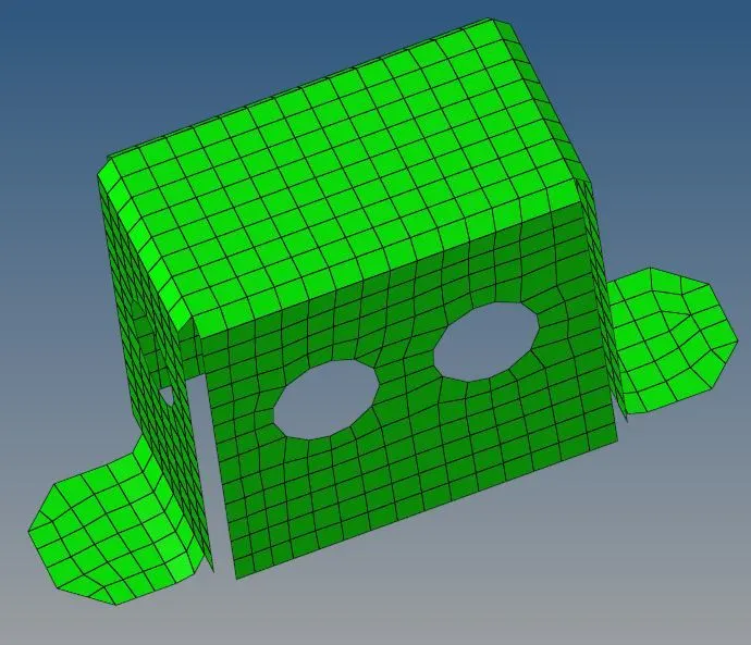
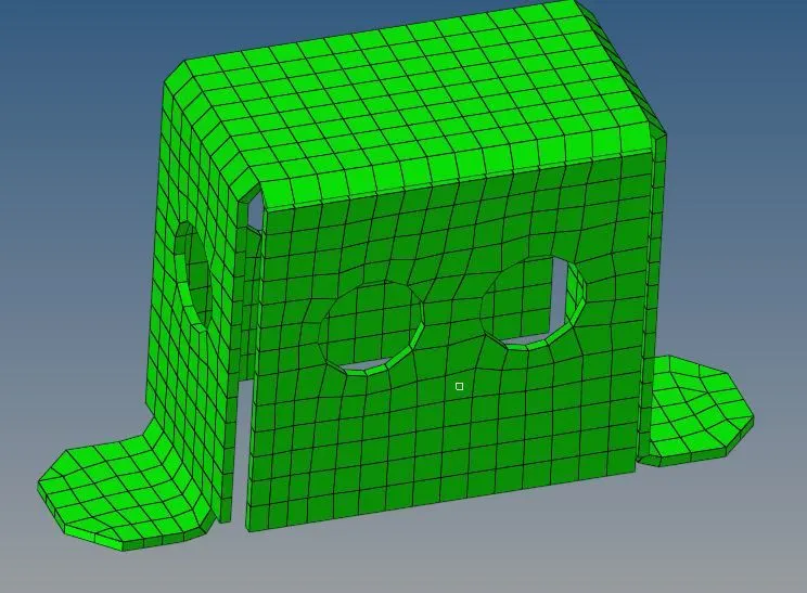
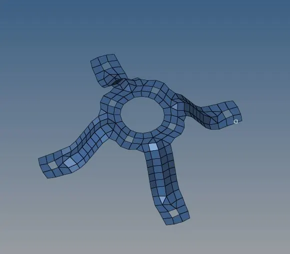
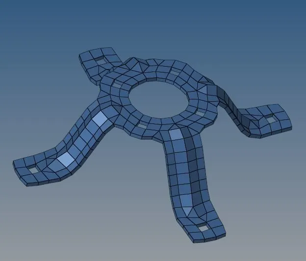
12.In the case of mounting bracket, Due to its symmetric sides of four. We can mesh the one instance and reflect the other three instances symeetrically by using centre reference point.
13. We need to create arc centre for the geometry by selecting geometry>nodes>arc centre. After this, select tool>rotate. Here we need to select the elements in one instance and assign angle as 90 degree. Now assign N1, N2, N3 points for a reference plane for rotation. Now select the base point as arc centre that we created earlier. now select rotate +. the mesh is created for other instance.
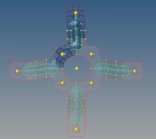
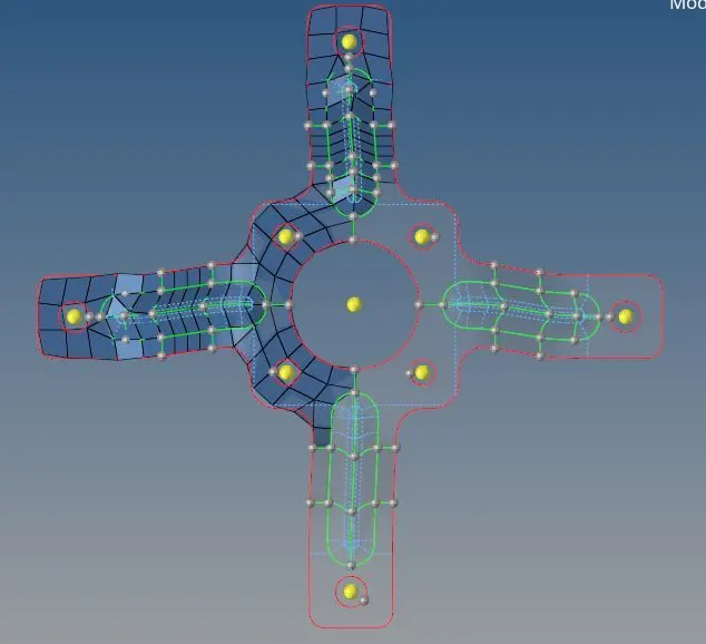

14. Next step we need to reflect the elements for other two instances. we need assign angle as 180 degree. select the elements of two instances. Follow the same procedure for selecting N1,N2,N3 points and base point. select rotate + and the mesh is created for other two instances.
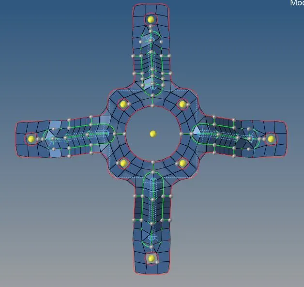

15. Now we have to equivalence the elements nodes over reflected area by selecting tools>edges. select preview equivalence and apply tolerance value from 0.2mm to 2mm to equivalence the nodes. Now select the equivalence to conncet the nodes.
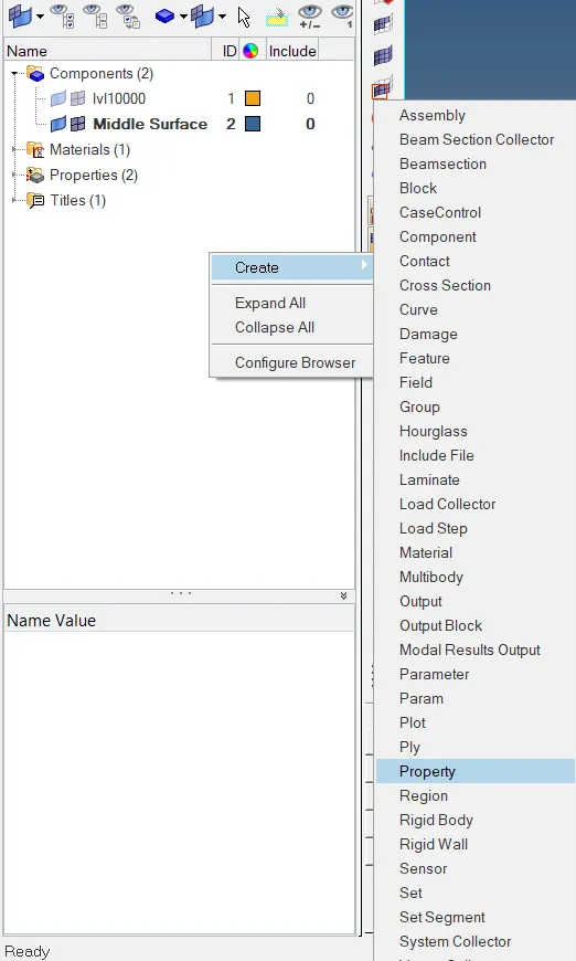
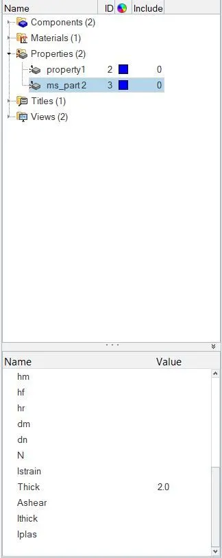
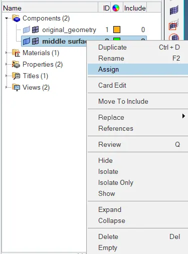
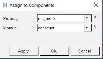
16. Finally after mesh the components, we need to assign thickness for the meshed surfaces by selecting New>property. assign thickness as per the requirement. now we need select the component we want to assign the thickness. In bottom of the specification tree we can see the property tab. select the tab and assign the property ID as shown below.
Final model images:
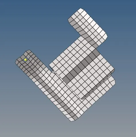
Practice model
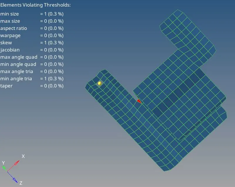
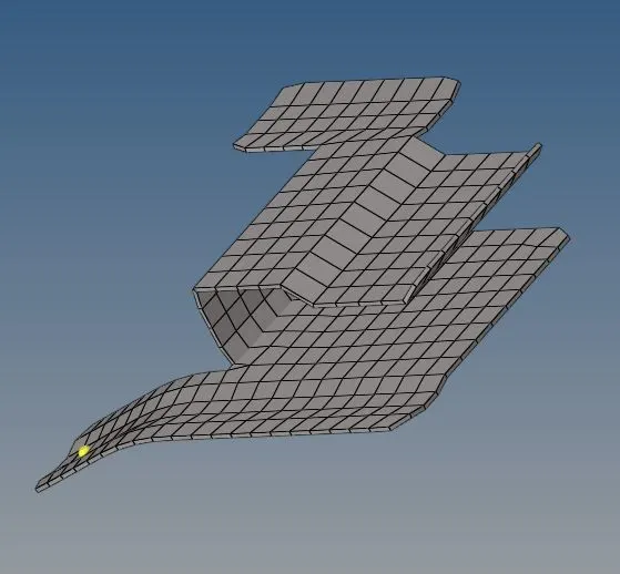
Due to feature line capturing, one element was failed for minimum length.
clip repair
mounting bracket
Conclusion:
The given components geometry were cleaned up and generated mid surface and meshed as per the given quality criteria and assigned thickness for the meshed surfaces.