Bird Strike on aero engines using LS-Dyna
Objective:
To simulate a non-linear transient dynamic problem of bird strike on aero engines using explicit analysis in LS-Dyna and evaluate the results.
Introduction:
- This is a classic nonlinear transient dynamics problem similar to a car crash and mobile drops. While accurate modeling of the problem requires advanced techniques such as SPH, this problem can be solved using a generic explicit solver. Here is the information required to model the phenomenon.
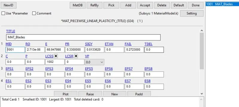
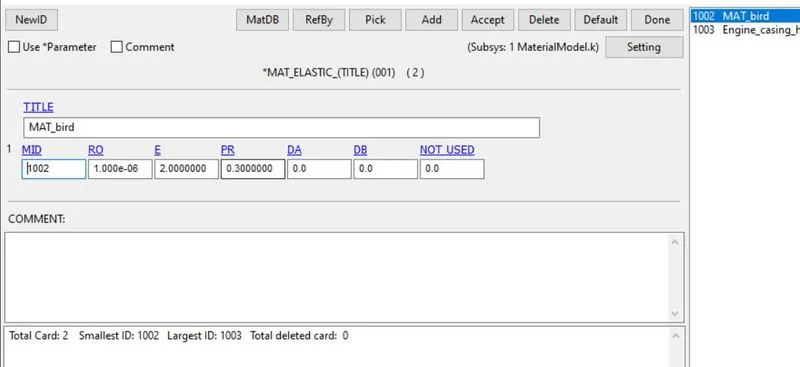
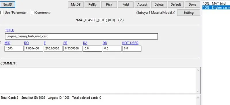
- The blades should rotate at a constant velocity but the casing should remain stationary. The cylindrical bird model should travel along its own axis and hit the blades. Use elastic material(MAT_001) for the bird(2GPa) and the casing(200GPa). The material model for the blades is attached(MAT_24 piecewise plasticity). The velocity of the engine blades and the birds can be chosen so that blade failure can be seen within a short span of time.
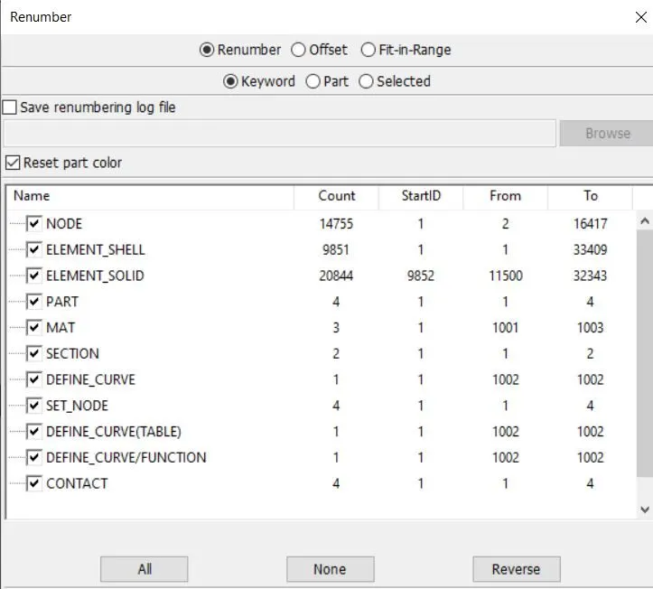
- Follow a consistent numbering approach of 100000+ for nodes, 500000+ for elements, and 1000+ for the parts. All other keywords should be numbered within 10000-19999 while following a range for each one.
- The bird, casing, and the blades should be in different input files and there should be one main file referencing all the input files. The main file should contain only references. Control cards and boundary conditions should be there in another separate file. The reference includes path should be such that the folder can be copied anywhere and it is able to correctly reference all the files and run the simulation.
Theory:
Bird strike, also known as avian ingestion, is the collision between a bird and an aircraft. Bird strikes have always been a cause of worry in the aeronautical industry. Aircraft both old and new have suffered from bird strikes. Jet engine ingestion occurs when the bird hits the jet engine of an aircraft and gets sucked in. Given that the fan blades rotate at a high rpm, a bird strike on a fan blade causes its displacement into the adjacent blade. This leads to a cascading failure, wherein the entire system fails, thereby resulting in a lot of damage.
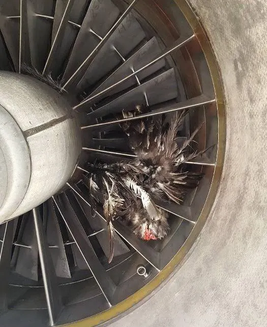
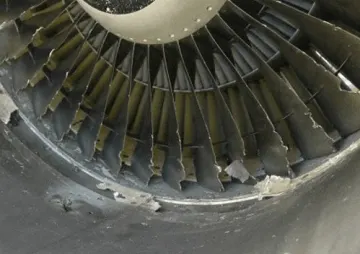
The force of the impact on an aircraft depends on the weight of the animal and the speed difference and direction at the point of impact. The energy of the impact increases with the square of the speed difference. High-speed impacts, as with jet aircraft, can cause considerable damage and a catastrophic failure even to the vehicle. The point of impact is usually any forward-facing edge of the vehicle such as a wing leading edge, nose cone, jet engine cowling, or engine inlet.
Procedure:
Now open the given model file in LS-Dyna. go to open>ls-dyna keywords. The file contains four parts as Engine casing, hub, blades, bird. we need to save them as individual part files. we need to create material, section, contact, control, boundary, and database cards in individual files and include all the files in one empty file using the include keyword.
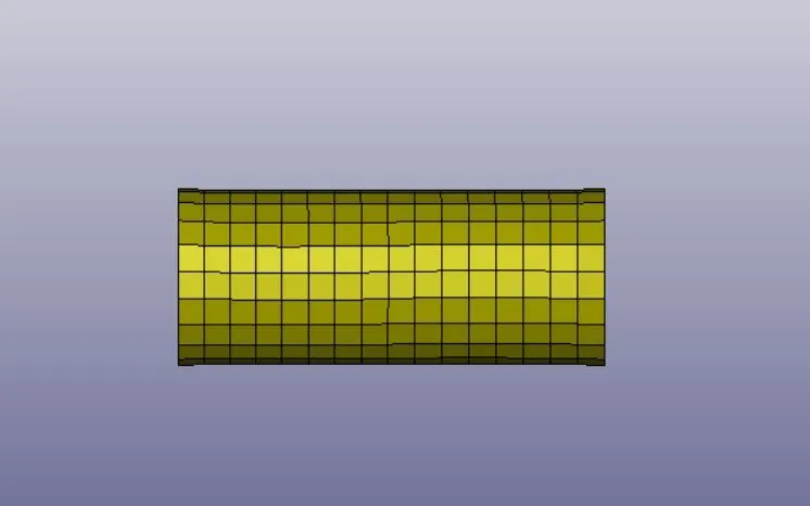
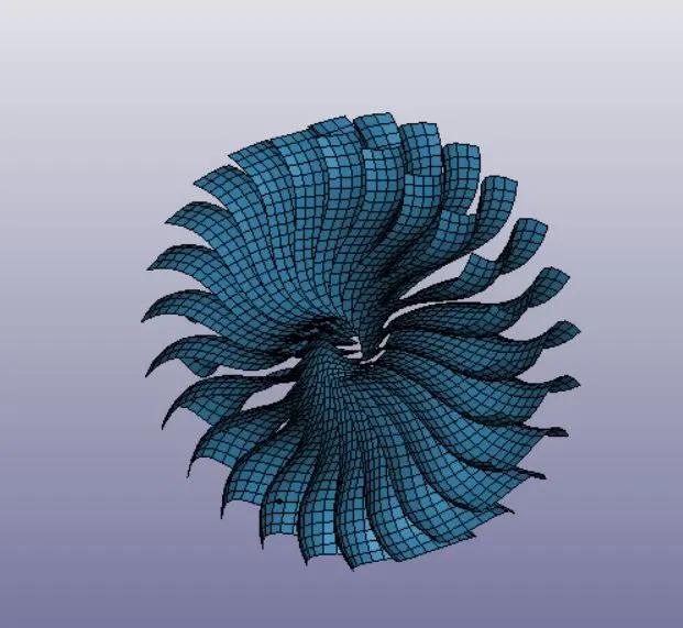
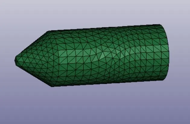
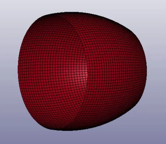
Now Renumber the nodes, elements, part id numbers in an organized way as per industrial standards.
Defining material card:
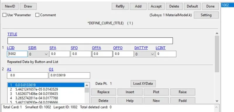
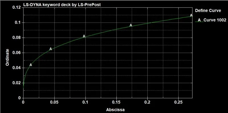
Now open the given material card file. Here we have a material card for blades (MAT_24 piecewise plasticity). now we need to define material cards for the Engine casing, hub, and bird. here define Elastic material card(MAT_001_Elastic) for Engine casing, hub and bird. For bird model, we need to give different parameters. For engine casing&hub, we should give different parameters. the images are shown below.
Defining section card:
Now define a Section card for both shell and solid elements. Here we need to define shell section and define elform as 16 for fully integrated points and thickness as 1mm. For solid elements, Elform as 10.
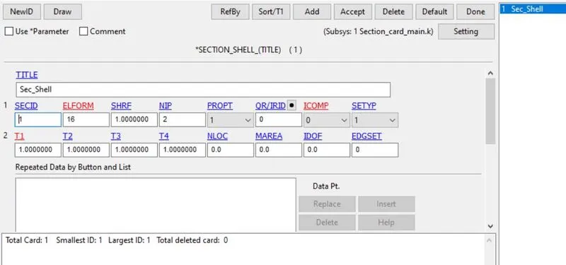
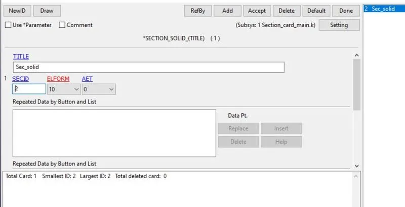
Defining section and mat id in parts:
open the part in ls-dyna. now go to the part card. define section and material id in the part card.
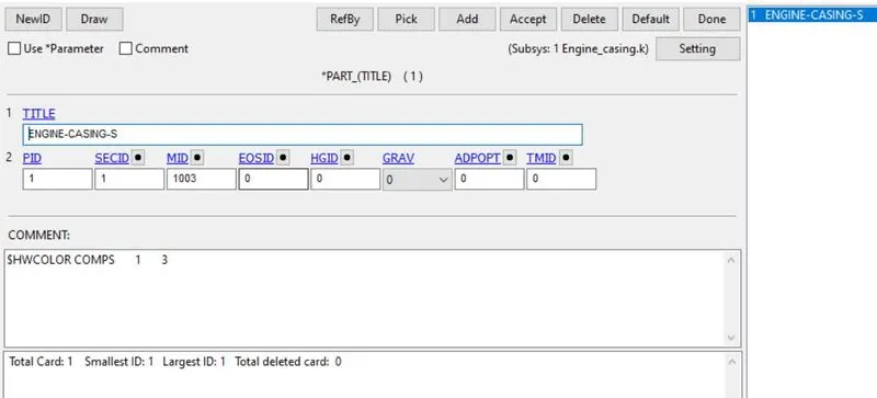
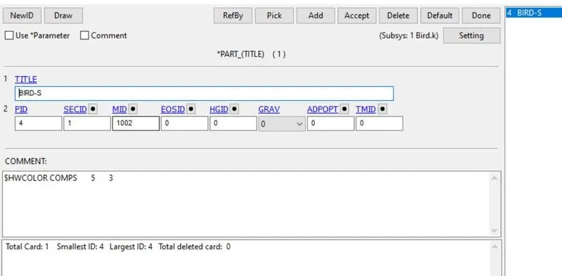
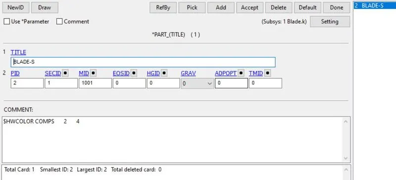
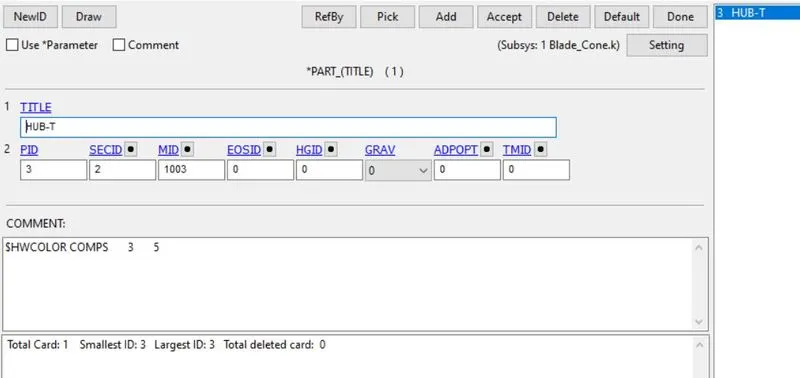
Defining boundary conditions:
Now Define boundary conditions for engine casing, blades and bird model. Now create node-set for the model using model>create entity>set_node. create four set of nodes for four different models. Now open an empty file. Go to model>keywords>Boundary>spc_set. Now define the engine casing node-set and fix all the DOF's.
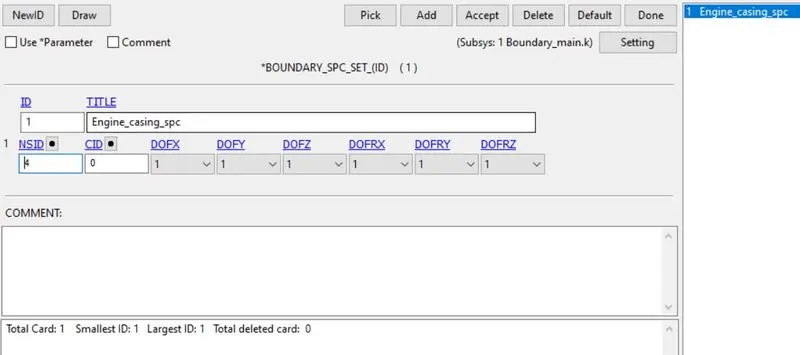
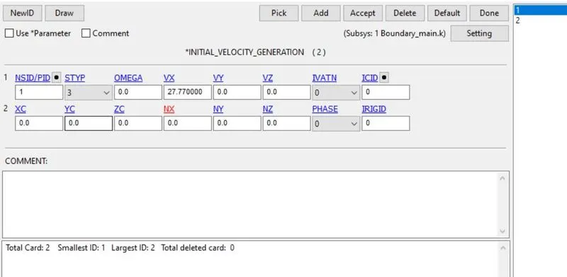
Now define the initial velocity for blades and bird. Now go to initial>velocity_generation. define initial velocity for blades. here we need to define angular velocity for blades. the blade will rotate at 3000 RPM.
`2pir/60=(2*pi*3000)/60`=314rad/sec=0.31 rad/ms.
So angular velocity is 0.31rad/ms and NX is x-direction cosine.
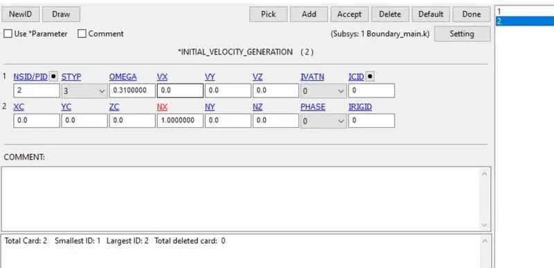
Define the initial velocity for the bird. here we need to define velocity in the x-direction at 27.77mm/ms(100kmph).
Defining contact card:
Now we need to define contact cards for engine casing and blades, blades and hub, blades and bird.
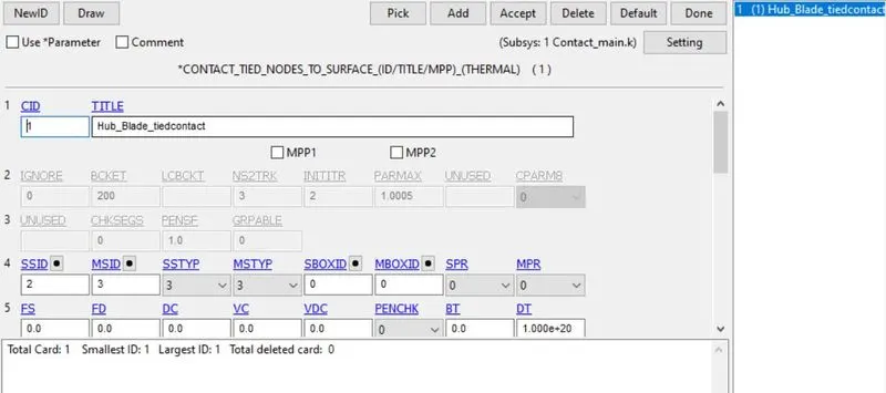
Contact b/w blades and hub:
define contact card using model>keywords>contact>automatic_tied nodes to surface. define slave and master set type as part id. now define slaves as blades because we need to find stress and strain in the blades. master as a hub. here we need a hub to rotate with the blades in the same angular velocity that why do we use tied nodes to surfaces.
Contact b/w blades and bird:
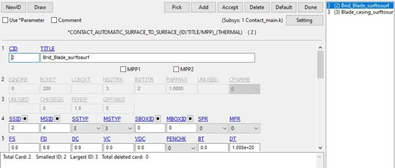
define contact card using model>keywords>contact>automatic_surface to surface. define slave and master set type as part id. now define slaves as blades because we need to find stress and strain in the blades. master as a bird.
Contact b/w blades and casing:
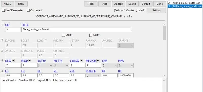
define contact card using model>keywords>contact>automatic_surface to surface. define slave and master set type as part id. now define slaves as blades and master as engine casing.
Self-contact with blades:
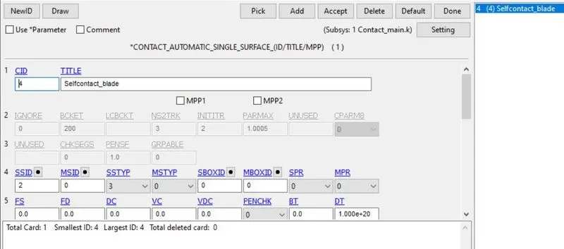
define contact card using model>keywords>contact>automatic_single_surface. define slave master set type as part id. now define slaves as blades. here we should define only slave part because it will contact itself.
Defining Database:
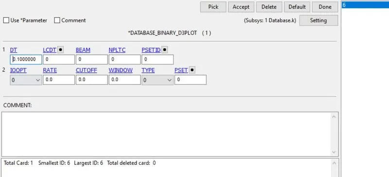
here define database using model>keywords>database. we need to define ASCII, binary d3plot, Extent_binary. In ASCII, we should define GLSAt, MATSUM, NODOUT, RCFORC,SLEOUT. define DT value as 0.1.
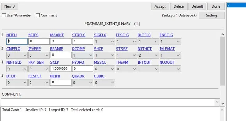
For binary d3plot, define DT value is 0.1. For Extent_binary, assign STRFLAG as 1. STRFLAG is used to define plastic strain data outputs.
Defining control card:
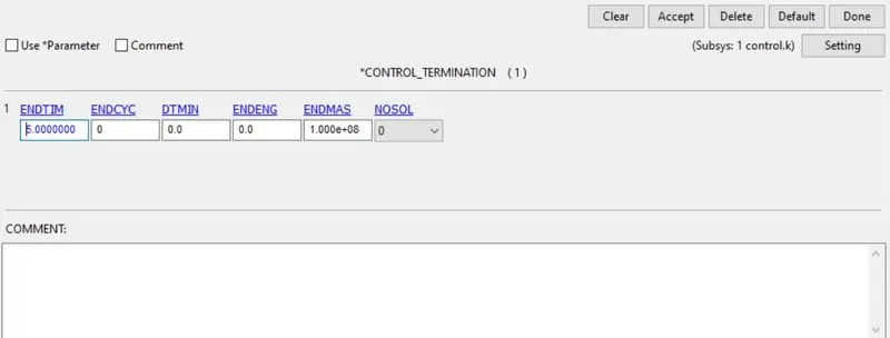
define control termination card in model>keywords>control>termination. assign end time as 5ms.
Define control time step card in model>keywords>control>timestep. here assign TSSFAC and DT2MS values to reduce the timestep of the simulation. Define TSSFAC as 0.9 and -5.0e-4.
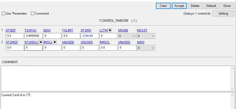
The final value is assigned for TSSFAC & DT2MS:
Including all sub files into a single file:
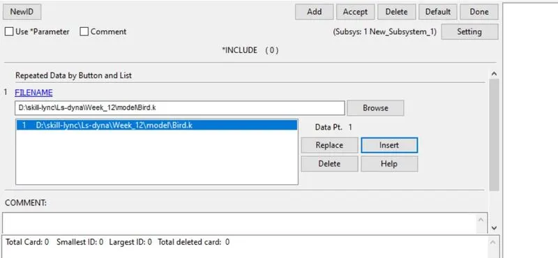
Now open an empty file. go to model>keywords>include>include. Now browse the subfiles in the file directory. Now select insert to include the subfiles. After including all sub-files. select save and done. Now all sub-files are included in a single file.
Now run the simulation. here we have to do a trial and error method to reduce the time step using the control_timestep card.
At first, TSSFAC=0.96 and DT2MS=-5.0E-4. now we have more mass is added and time step also increased. so we need to decrease the value. do the same step till the mass percentage will come below 5%.
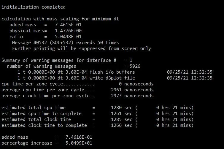
TSSFAC=0.96 and DT2MS=-4.0E-4
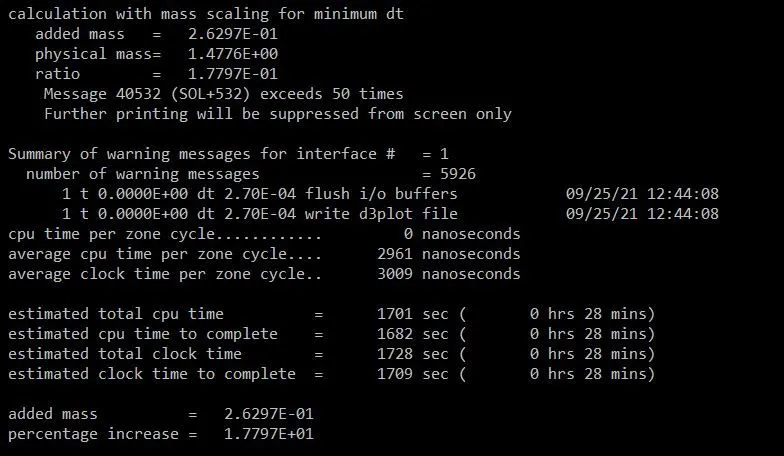
TSSFAC=0.96 and DT2MS=-3.0E-4
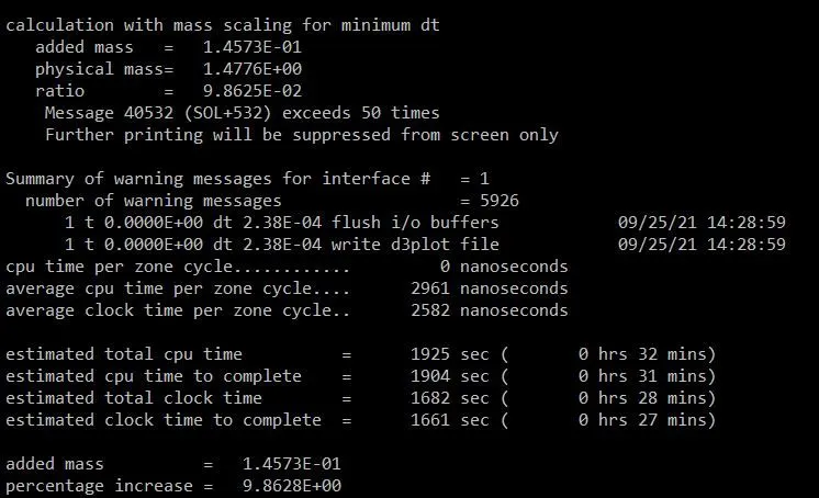
TSSFAC=0.96 and DT2MS=-2.70E-4
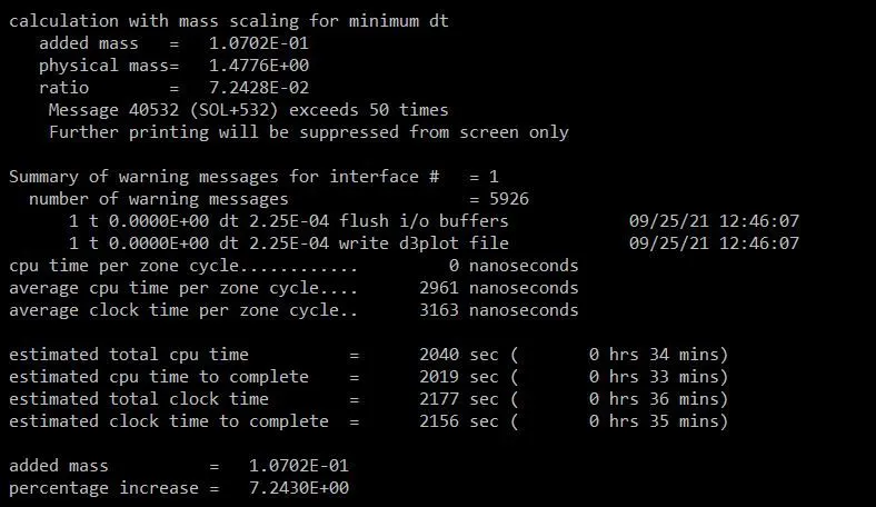
TSSFAC=0.96 and DT2MS=-2.5.0E-4
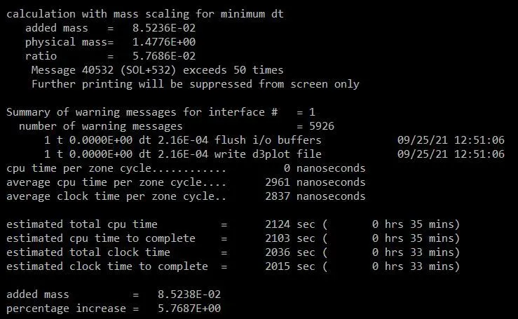
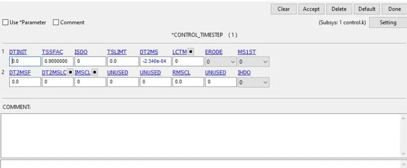
TSSFAC=0.96 and DT2MS=-2.34.0E-4
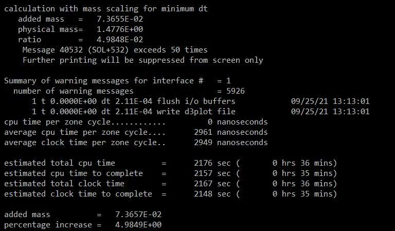
Now run the simulation using control_timestep card values as TSSFAC=0.96 and DT2MS=-2.34.0E-4.
Results:
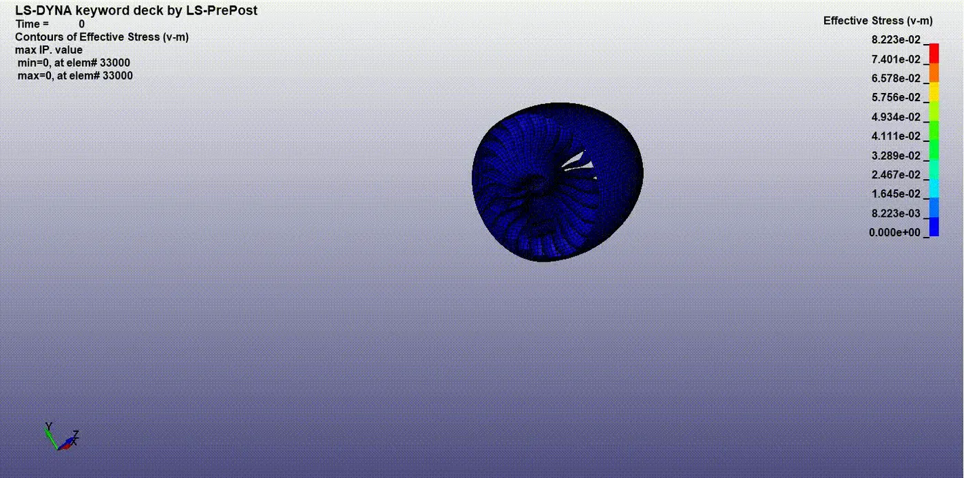
Effective stress:
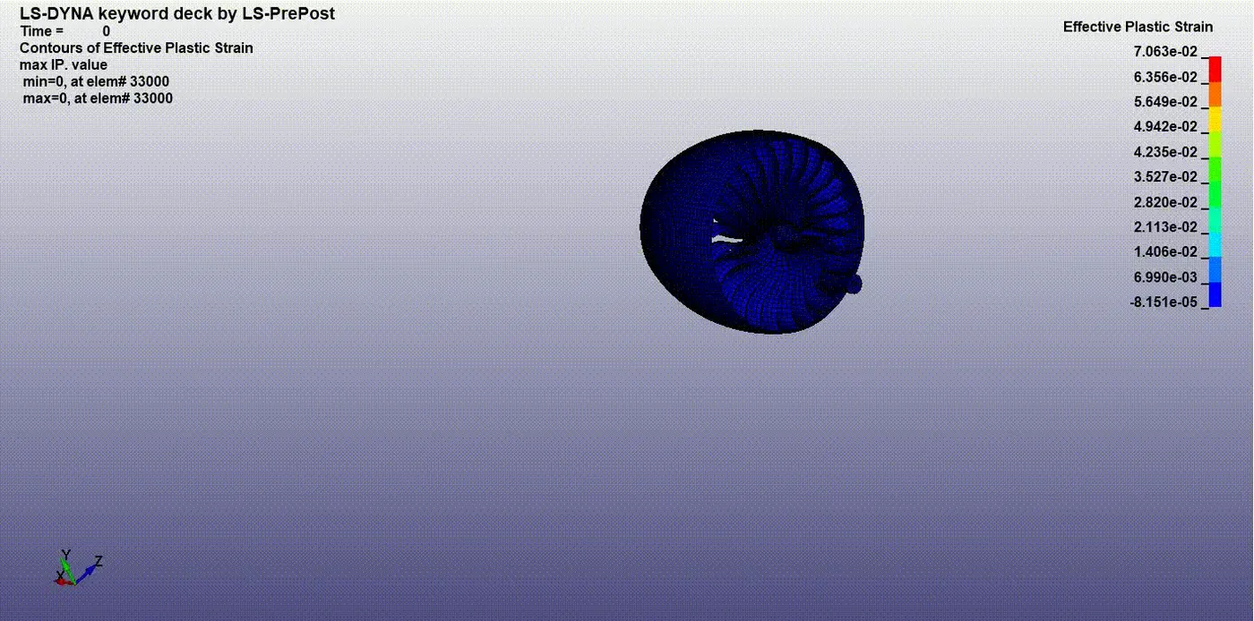
Effective plastic strain:
Effective stress vs time plot:
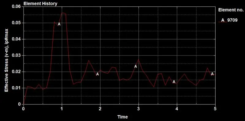
When the bird had an initial velocity of 100kmph when it hit the blades. The maximum stress is induced on the blade of 0.057Gpa at 1ms. the blades were rotated at 0.31 rad/ms.
Effective plastic strain vs time plot:
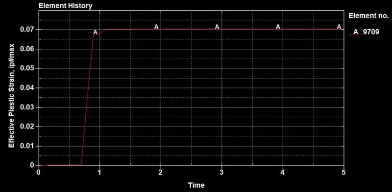
When the bird had an initial velocity of 100kmph when it hit the blades. The maximum plastic strain is induced on the blade of 0.07 at 1.1ms. the blades were rotated at 0.31 rad/ms.
Global statistics energy plot:
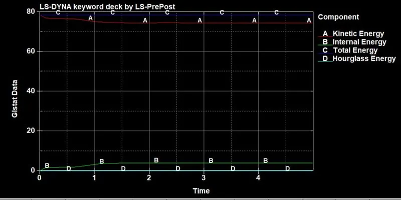
In explicit analysis, the bird hit the blades due to the impact. the kinetic energy decreases and the loss of energy are absorbed internally. so that the internal energy increases at the time of impact. Hourglass energy is zero and constant due to the element formulation.
Contact energy plot:
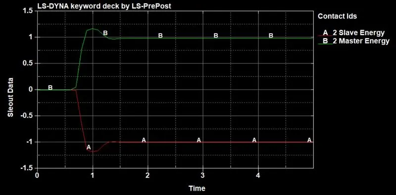
The contact energy between the bird and the blades is shown below. it shows that when the time of impact the blades as slaves are absorbing the kinetic energy from the bird as a master segment.
sliding energy plot:
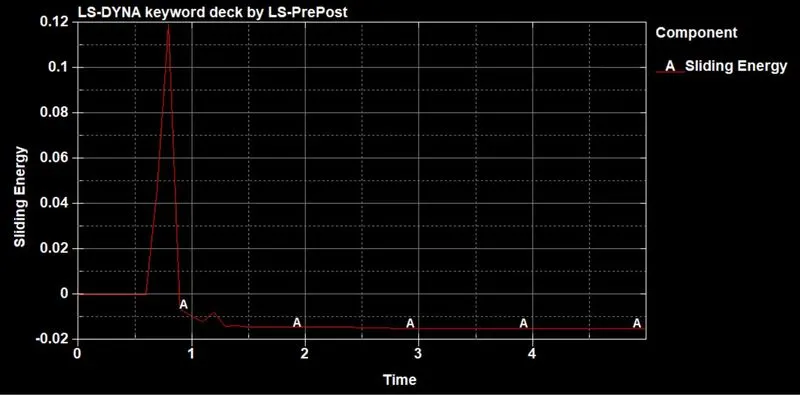
After the time of impact, the bird slides over the blades slightly. so that the sliding energy occurs slightly after the impact. it is shown above.
Conclusion:
The given model is assigned by different parts id, material, section, contact, boundary, control, and database cards. Mass scaling is performed and obtained results below 5%. The energy and stress-strain plots are obtained using the output results.