Assignment 2-RADIOSS Engine File Editing & 3D Meshing Challenge
Objective:
To answer the given questions by calculating the speed of sound and edit the RADIOSS engine file.
Procedure:
1. Calculate the speed of the sound in steel rail.
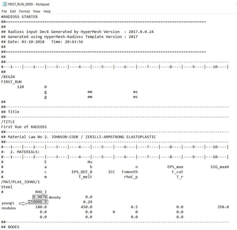
Young's modulus(E)= 210000MPa
density(ρ)= 0.0078 g/mm3
Speed of sound, c=`root`(E/`rho`)
c=`root`(210000/0.0078)= 5188.75 mm/ms
2. Time taken for a shock wave to travel a length of 1000mm from one end of the rail to other end.
Length, l=1000mm
Time taken,`Delta`t =l/c=1000/5188.75= 0.1927ms
3. The length of the rail is the value mentioned in above question.2.
So, Length is 1000mm, so time taken is 0.1927ms.
4. Here we have question for the termination time is equal to the time takes to travel the length of the rail.so the calculated time taken value above the question.2 is equal to termination time.
So, the termination time is 0.1927ms.
5. For 20 animation steps given in the question.
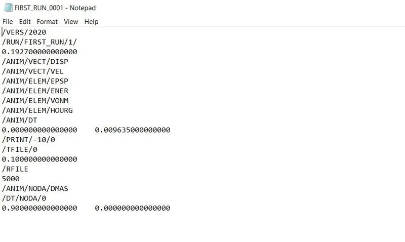
So, Tfreq= time taken/no.of.steps = 0.1927/20= 0.009635ms
6. All the answer for the above question and change print -10 value assign in engine file as shown below.
Result:
Conclusion:
The given questions are calculated as per the formula and the engine fileis edited as per the given question.
7.3D Meshing of the given component.
Objective:
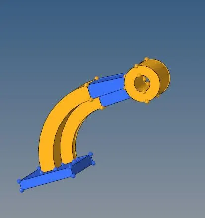
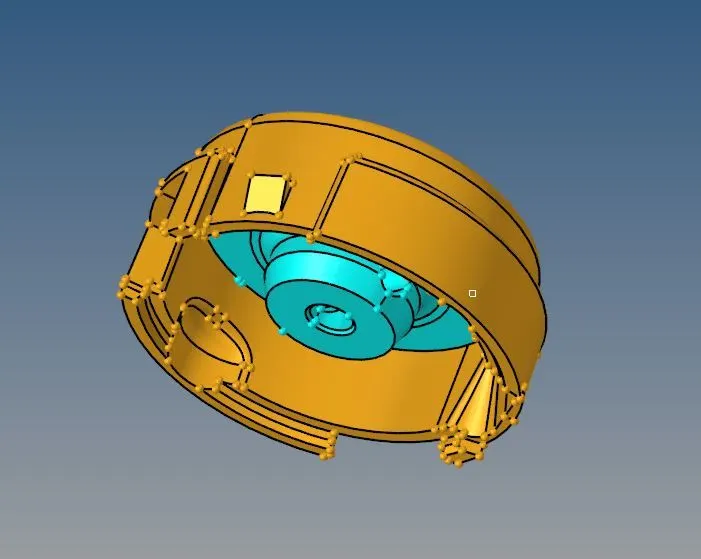
To mesh the given components using 3D elements. The arm bracket is to be meshed using Hexa 3D elements. The Housing component is to be meshed using tetra meshed elements. Check the elements as per the given quality criteria.
Target element length=5mm (Tetra)
Target hexa element length=10mm
Tet collapse=0.150
Procedure:
Model images:
Arm bracket
Housing
Hexa meshing for Arm bracket:
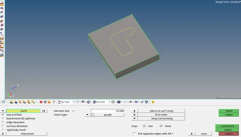
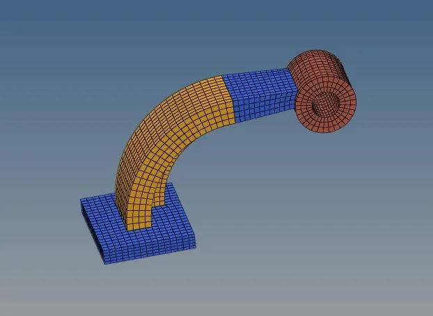
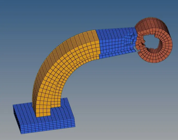
1. At first we have to mesh the top face of the base part which is attached to arm curve. Here we use automesh tool for mesh the surface 2D>automesh. assign target element length as 10mm and element type as quad.
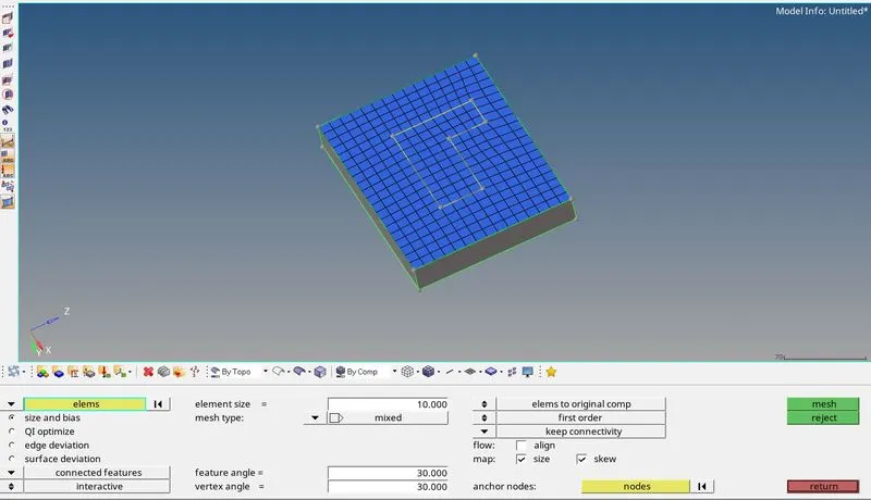
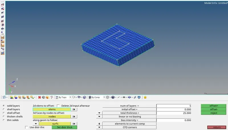
2. Now we should create hexa elements using 2D quad elements by element offset tool in 3D>element offset. Select elements and select the along side surface as side surface of the base part. assign no.of.layers as 5 and thickness as 25. Now select drag + to create hexa elements over unmeshed surfaces.
3. Now we should mesh the arm curve area. We can generate 3D elements using the elements within imprint in the base of arm curve. we should select the tool 3D>spin for creating 3D elements. We need to given spin value as 90, no.of.layers as 25, set the axis of rotation as x direction & base point (it can be created using geometry>nodes>arc centre and select the curve line of the arm curve). Now select spin + for generate 3D elements.
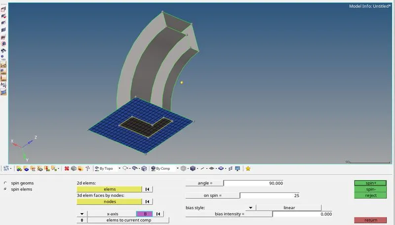
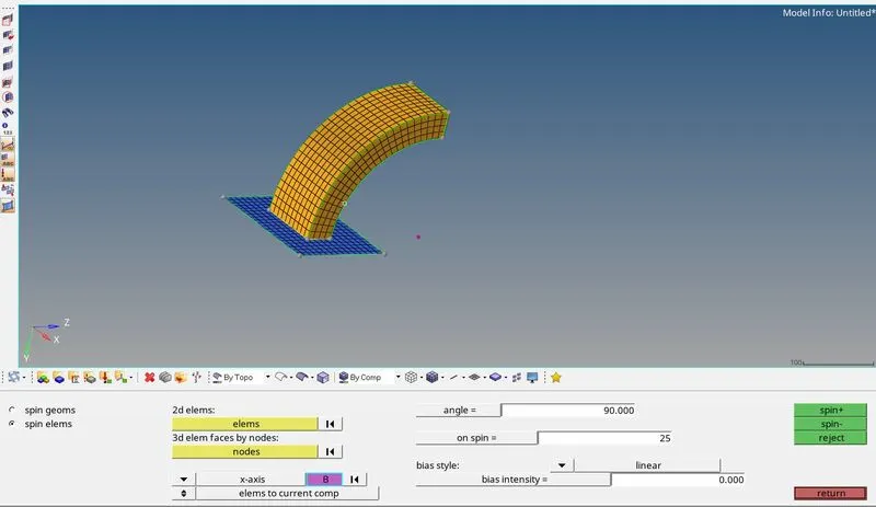
4. Now we have to mesh the arm straight part by using linear solid tool in 3D>linear solid. For this we have to mesh the other end surface and match the meshed surface with the mesh generated in imprint area of arm straight part in arm curve part. After matching the mesh we can use linear solid tool for generate the 3D elements. select the elements in one end surface and select the elements from other end surface individually. Now select the reference nodes in one end surface and select the same nodes in the other end. Now assign no.of.layers as 12. select solids to generate the 3D hexa elements.
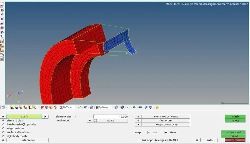
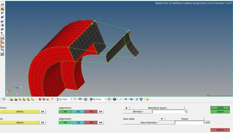
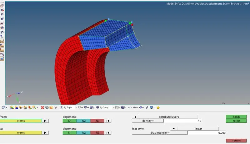
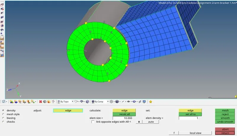
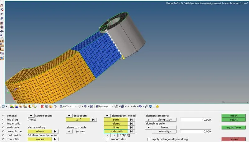
5. Finally we need to mesh the boss part. Here we have other method to generate the elements called solid map in 3D>solid map. We should map the one end ofelements into other end so, we should mesh the one end surface using 2D shell elements without rotating quads. We can match the meshing nodes equally for good mesh flow. After meshing, we should project the end nodes to the end line for mesh path using tool>project. After project the node, We can generate the mesh by selecting destination surface as other end surface, select elements for mapping, select line and nodes over the elements there to path for mapping. Now select mesh to generate 3D mesh over boss part.
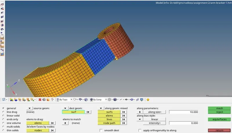
6. Now delete the 2D shell elements using delete tool. Also Equivalence the nodes using tool>edges>equivalence.
Tetra meshing for Housing component:
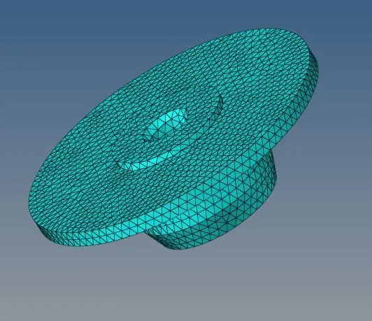
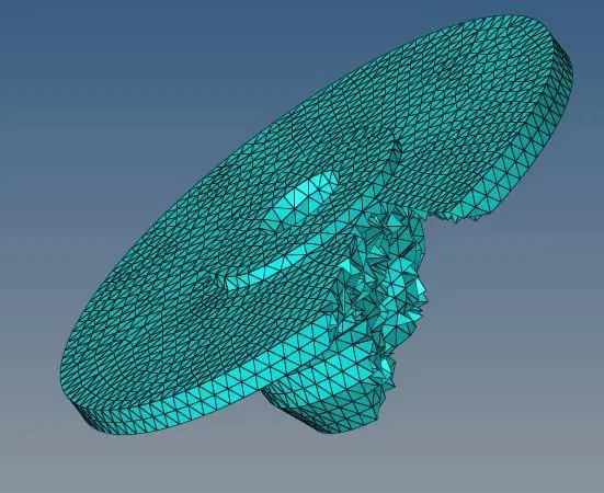
1. Here this model has two components such as cover and hub. We should do the mesh one by one first cover part and then do for hub part. Now we can go for mesh before that assign target element as 5mm and element type as tria. we can mesh directly over the surfaces.
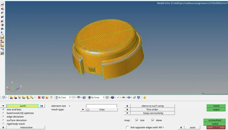
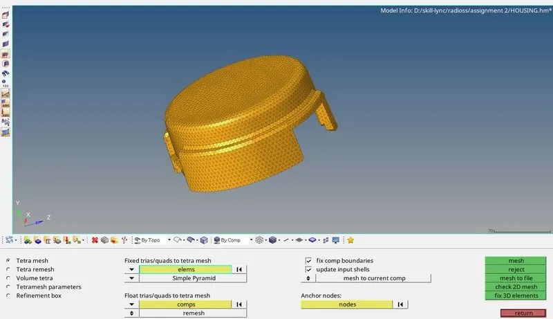
2. After the 2D tria elements are generated. We can move to create 3D tetra elements using 3D>tetramesh. Select the 2D tria elements and select mesh. Now the 2D tria elements are changed into solid tetra elements. After this we can check for element failed for tet collapse in tool>check elements>tet collapse as 0.150.
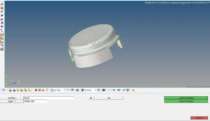
3. Now we should delete the 2D tria elements by using delete tool. select this config as tria3 for this.
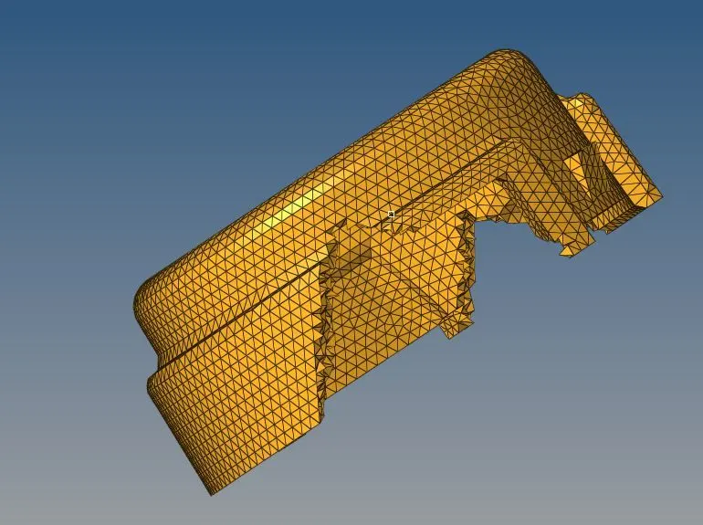
4. We can repeat the same procedure for hub part.
3D mesh model:
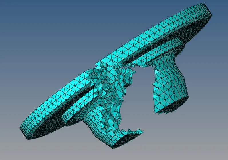
Result:
Arm bracket
cover

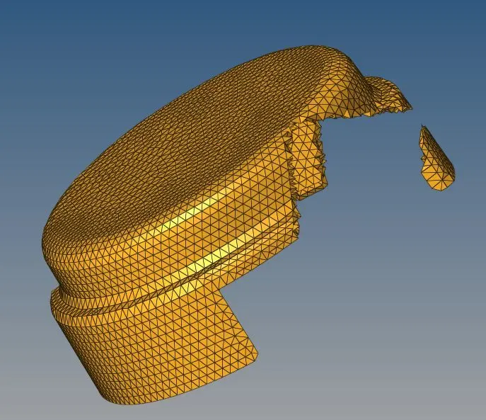
hub
Conclusion:
The given Arm bracket and housing components are 3D meshed as per the given quality criteria.