Stress Concentration on a Plate with hole
Objective:
- To design the two different rectangular plates with different kinds of holes using the Ansys space claim modeler.
- To Perform Static analysis on the plates using structural steel material.
Procedure:
Case:1
Design the Rectangular plate with a thickness of 30mm.
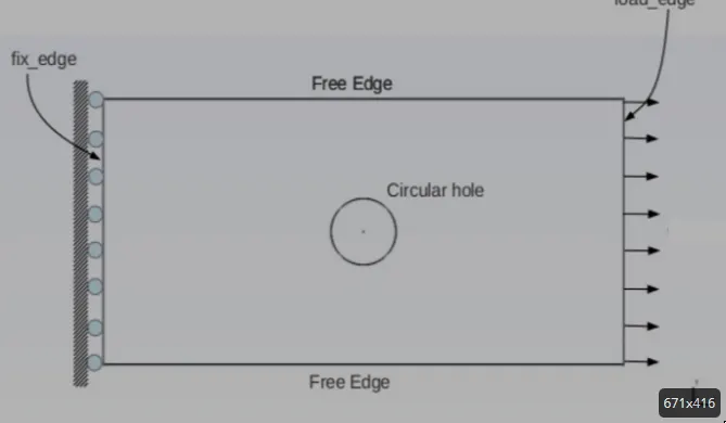
Plate dimensions:
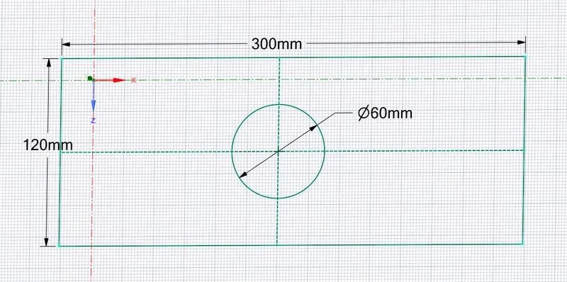
Length=300mm
Height=120mm
Thickness=30mm
Circular Hole at the center:
Diameter=60mm
Now using a space claim modeler, Create 2d rectangular geometry with a hole at the center of 60mm.
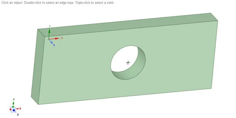
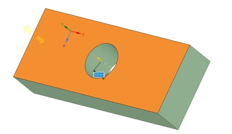
Now extrude the geometry using the pull tool in the space claim. Here we have extruded model with a thickness of 30mm.
Defining material:
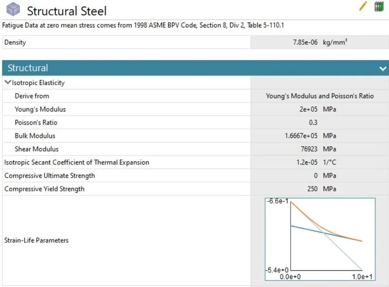
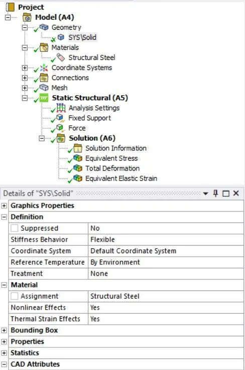
Now go to material>edit>structural steel. Assing the material for the geometry.
Creating mesh:
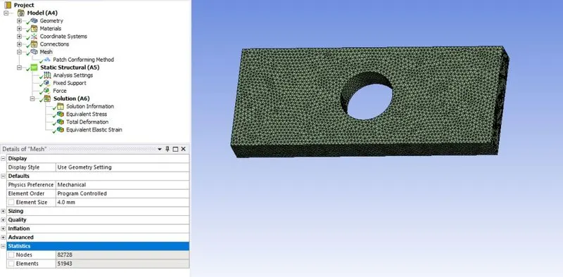
Now go to mesh>edit. Define element size as 4mm and element type as tetrahedral. Now right click>generate mesh.
Defining boundary conditions:
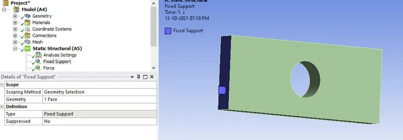
Now define fixed support on the left side of the geometry using right clk>insert>fixed support. Now select the face and click ok.
Now define force on the right side of the geometry using right clk>insert>force and assign value as 500N. Now select the face and click ok.
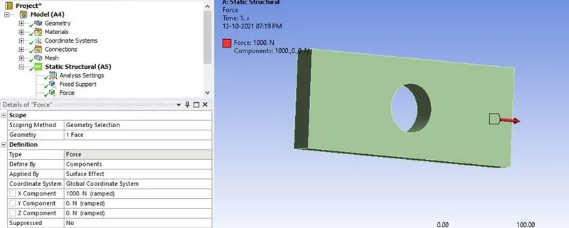
Defining outputs:
Now define outputs for the geometry using solution>right clk>insert>Total deformation, Von mises stress.
Case-1 results:
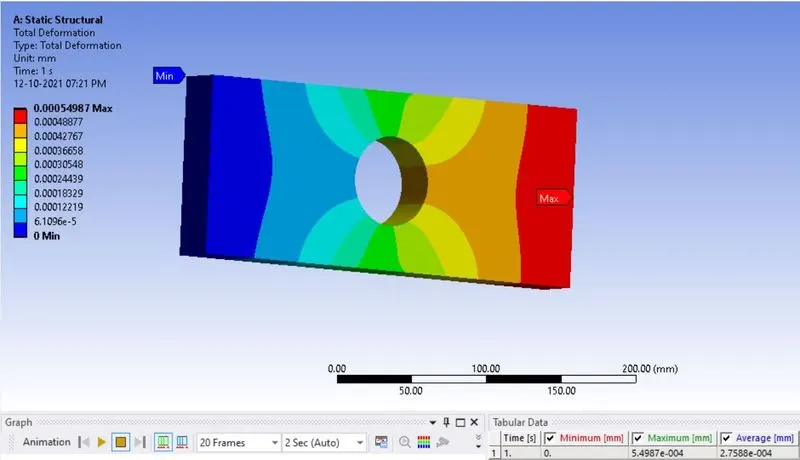
Total deformation:
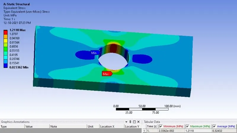
Von-mises stress:
Case:2
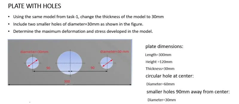
Design the Rectangular plate with a thickness of 30mm.
Length-300mm, height-120mm, thickness-30mm.
Now using a space claim modeler, Create 2d rectangular geometry with a hole at the center of 60mm dia and small holes beside the center hole of 30mm dia.
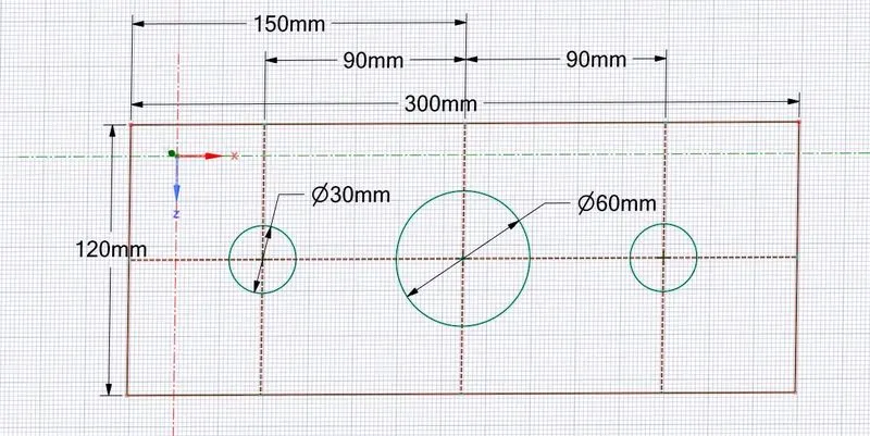
Now extrude the geometry using the pull tool in the space claim. Here we have extruded model with a thickness of 30mm.
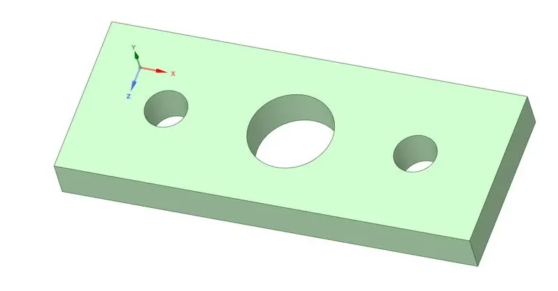
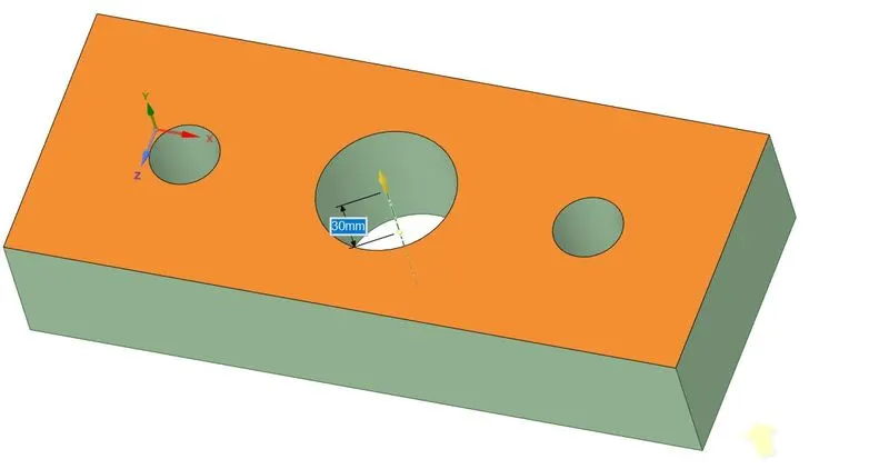
Defining material:
Now go to material>edit>structural steel. Assing the material for the geometry.
.
Creating mesh:
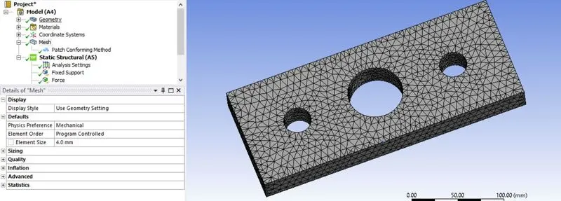
Now go to mesh>edit. Define element size as 4mm and element type as tetrahedral. Now right click>generate mesh.
Defining boundary conditions:
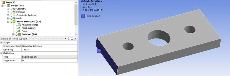
Now define fixed support on the left side of the geometry using right clk>insert>fixed support. Now select the face and click ok.
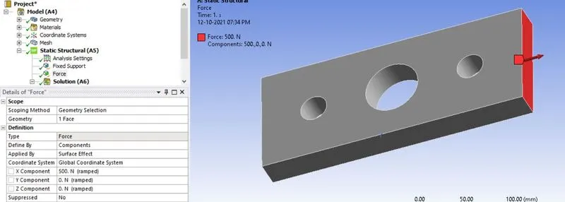
Now define force on the right side of the geometry using right clk>insert>force and assign value as 500N. Now select the face and click ok.
Defining outputs:
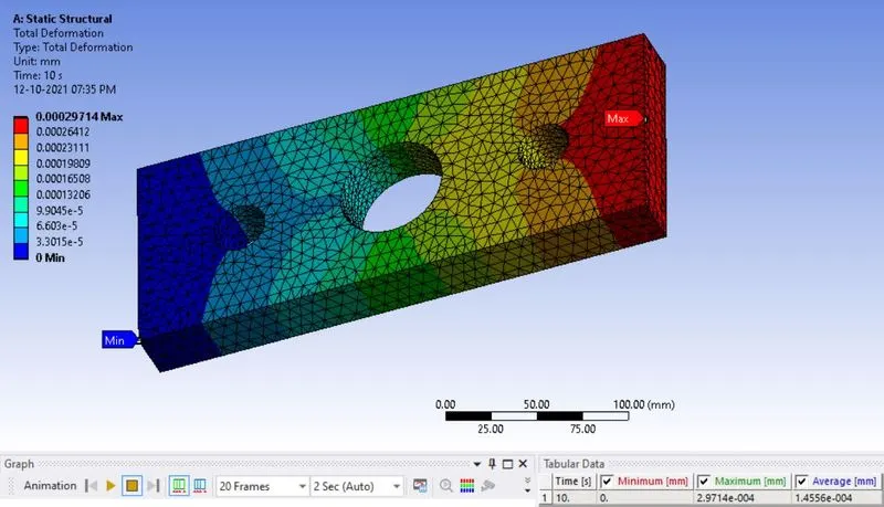
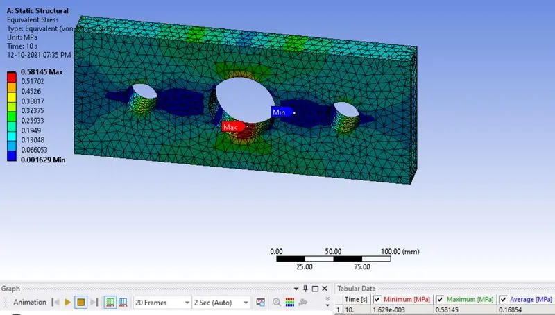
Now define outputs for the geometry using solution>right clk>insert>Total deformation, Von mises stress.
Case-2 results:
Total deformation:
Von-mises stress:
Results discussion:
| Solution | Case-1 | Case-2 |
| Maximum deformation(mm) | 5.498e-4 | 2.97e-4 |
| minimum deformation(mm) | 0 | 0 |
| Average deformation(mm) | 2.75e-4 | 1.45e-4 |
| Maximum equivalent stress(Mpa) | 1.2118 | 0.58145 |
| Minimum equivalent stress(Mpa) | 2.33e-2 | 1.629e-3 |
| Average equivalent stress(Mpa) | 0.3243 | 0.16854 |
Here in case-1, the maximum deformation occurs at 0.000549mm. In case-2, The maximum deformation occurs at 0.000297mm. When compared both cases, the deformation of case-2 is smaller than case-1 because the geometry has three holes at the position so that the deformation has a slower rate in case-2 compare to case-1.
Here in case-1, the maximum stress occurs at 1.2118Mpa. In case-2, The maximum deformation occurs at 0.58145Mpa. When compared both the cases, the Maximum stress of case-2 is smaller than case-1 because the geometry has three holes at the position so that the stress is distributed evenly to the model. so case-2 has less stress concentration on the hole area compare to case-1.
From an analysis standpoint:
In this point of view, Case-1 has a higher stress concentration on the hole area. In case-2, the stress concentration is lower in hole areas when compare to case-1. so that case-2 geometry has a lesser failure rate when compared to case-1 geometry.
From a manufacturing standpoint:
From a manufacturing point of view, case-1 geometry has a tip because it has less material wastage when manufacturing the model. The operations have gone through for the case-1 model as lesser than as case-2.
Conclusion:
The Geometry is created as per the dimensions given and the model gets meshed and done a static structural analysis on the model. The results are shown above and compared with another case.