Creating the various connectors like spot,seam,bolt to connect the various parts in given components from using tool of 1D,2D,3D using hypermesh
Challenge 9: Creating the various connectors like spot,seam,bolt to connect the various parts in given components from using tool of 1D,2D,3D.
Objective:
To create various connectors to attach the various parts of the given components.the connectors are used such as spot,seam,bold,spotweld.
Procedure:
- first import the model.
- the frame assembly consists of 9 components such as right rail 1&2,left rail 1&2,front truss 1&2,rear truss 1&2,reinf plate.
- connect those components with various connectors and assign material & property of thickness 1mm.
- we know which connectors to connect the components as given above use that connectors to connect.
| s.no | connecting parts | connectors | type |
| 1 | Right Rail 2 & Front truss 1 | seam | quad(angled+capped+L) |
| 2 | left Rail 2 & Front truss 1 | seam | quad elements |
| 3 | Right Rail 1 & Front truss 1, front truss 2 | spot | weld(3 layers with dia 5mm) |
| 4 | left Rail 1 & Front truss 1, front truss 2 | seam | hexa(adhesive) |
| 5 | Right Rail 2 & rear truss 2 | bolt | connector(general) |
| 6 | left Rail 2 & rear truss 2 | bolt | connector(general) |
| 7 | Right Rail 1,Right Rail 2 | spot weld | rigid elements |
| 8 | left Rail 1,left Rail 2 | spot weld | spring elements |
| 9 | Reinf plate & front truss 2 | spot | weld(3 layers with dia 5mm) |
| 10 | Front truss 2 & left Rail 2 | bolt | CBAR |
| 11 | Front truss 2 & right Rail 2 | spot weld | weld |
| 12 | Right Rail 1 & rear truss 2 | spot weld | spring |
| 13 | left Rail 1 & rear truss 2 | seam | hexa(adhesive) |
| 14 | rear truss 1 & rear truss 2 | spot weld | rod |
Right Rail 2 & Front truss 1:
- first hide all components and then unhide these two components.
- create a connector for these two components using seam as given below [1D+connector+seam+quad(angled+capped+L)]
- assign tolerance-10mm,spacing-4,weld angle-60,cap angle-45,run-off angle-10.
- now select the nodes and select the components and then create.
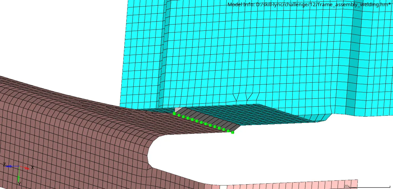
img.1 seam quad(angled+capped+L)
- after create the connector,some distortion on the 2D mesh, we have clear the mesh while using remesh or quality index.
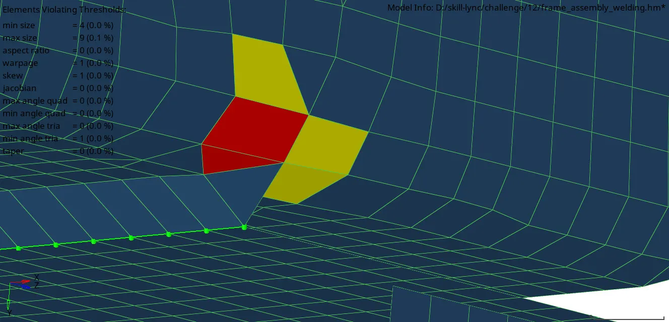
img.2 distorted mesh
- we can go with remesh those elements and get a good mesh flow.
left Rail 2 & Front truss 1:
- now hide that two components and then unhide these two components.
- first create a connector for these two components using seam quad by select[1D+connector+seam+quad]
- select tolerance as 10mm, spacing-4and then create.
- here we dont have any distortion in 2D mesh.
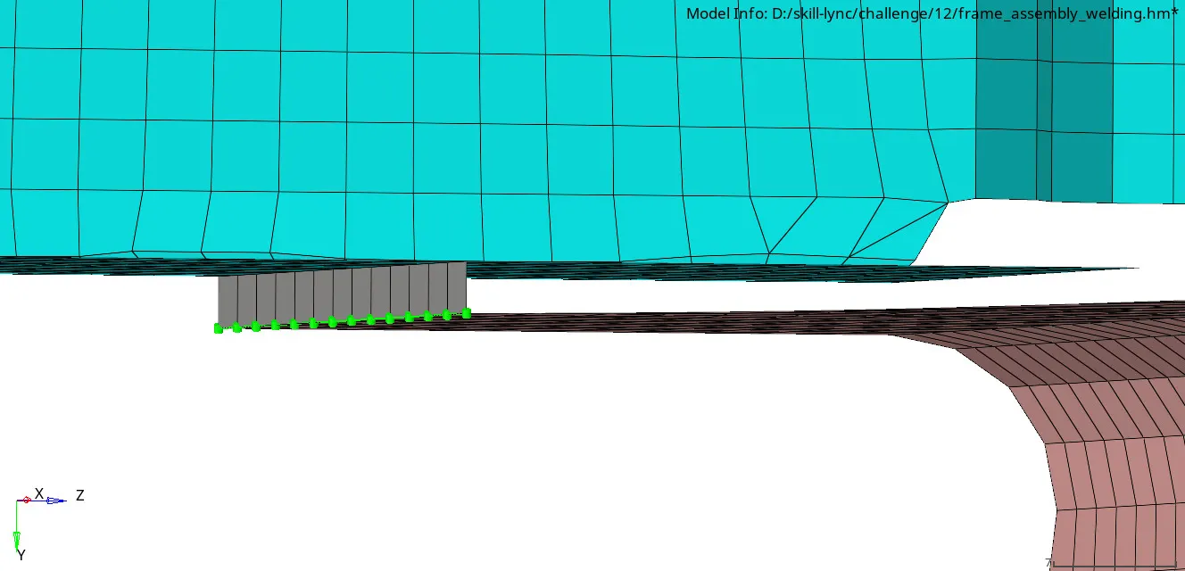
img.3 seam quad elements
Right Rail 1 & Front truss 1, front truss 2:
- now hide existing two components and then unhide these three components.
- first create a connector for these two components using spot-weld by select[1D+connector+spot+weld]
- select tolerance as 10mm, spacing-4, layer-3, diameter-5mm and then create.
- select the nodes & components to create the connectors.
- now the 2D mesh has no distortion.
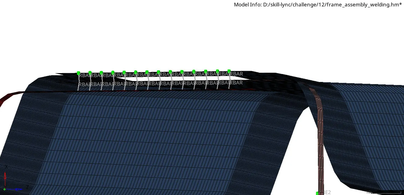
img.4 spot-weld connector
left Rail 1 & Front truss 1, front truss 2:
- hide all parts, now unhide these components.
- now we have to create seam+hexa(adhesive) by select(1D+connector+seam+hexa(adhesive)).
- assign tolerance-10mm, spacing-4, strip-1, coat-1 and then select node path and components.
- now create the connector.here we have no distorted 2D mesh.
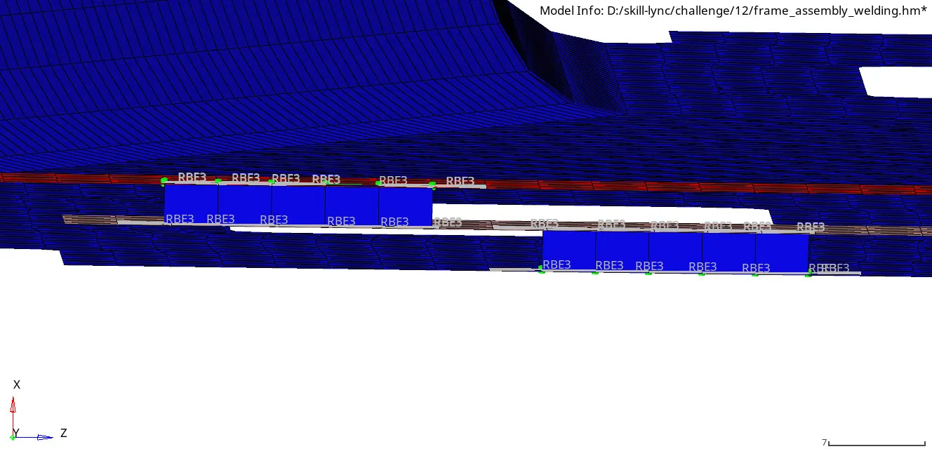
img.5 seam hexa (adhesive) connector
Right Rail 2 & rear truss 2:
- hide the componets and unhide these components
- to create bolt(general) connector 1D+connector+bolt+bolt(general)
- select tolerance-10mm, create hole if none, layer-2
- select nodes and components
- we had no distorted mesh.
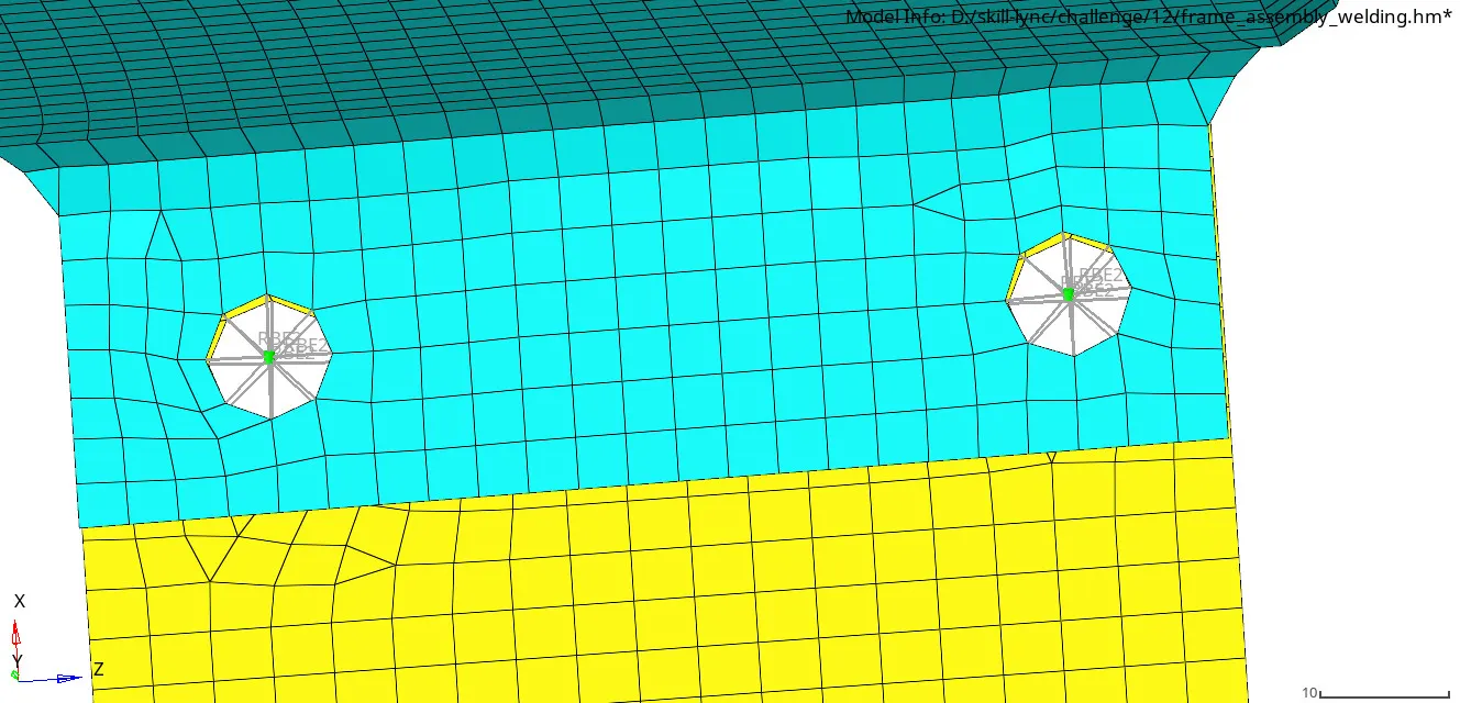
img.6 bolt general connector.
left Rail 2 & rear truss 2:
- hide all parts, now unhide these components.
- now we have to create bolt(connector) by select(1D+connector+bolt+bolt(general)).
- assign tolerance-10mm, create hole if none, layer-2 and then select node path and components.
- now create the connector.
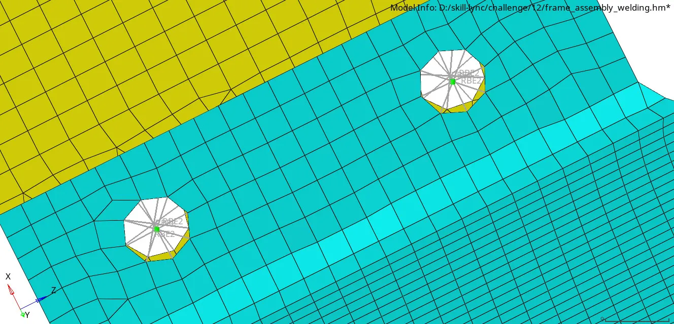
img.7 bolt general connector.
Right Rail 1,Right Rail 2:
- hide the other components and unhide these two.
- now select 1D+spot weld+rigid
- now select independent and dependent nodes and then create.
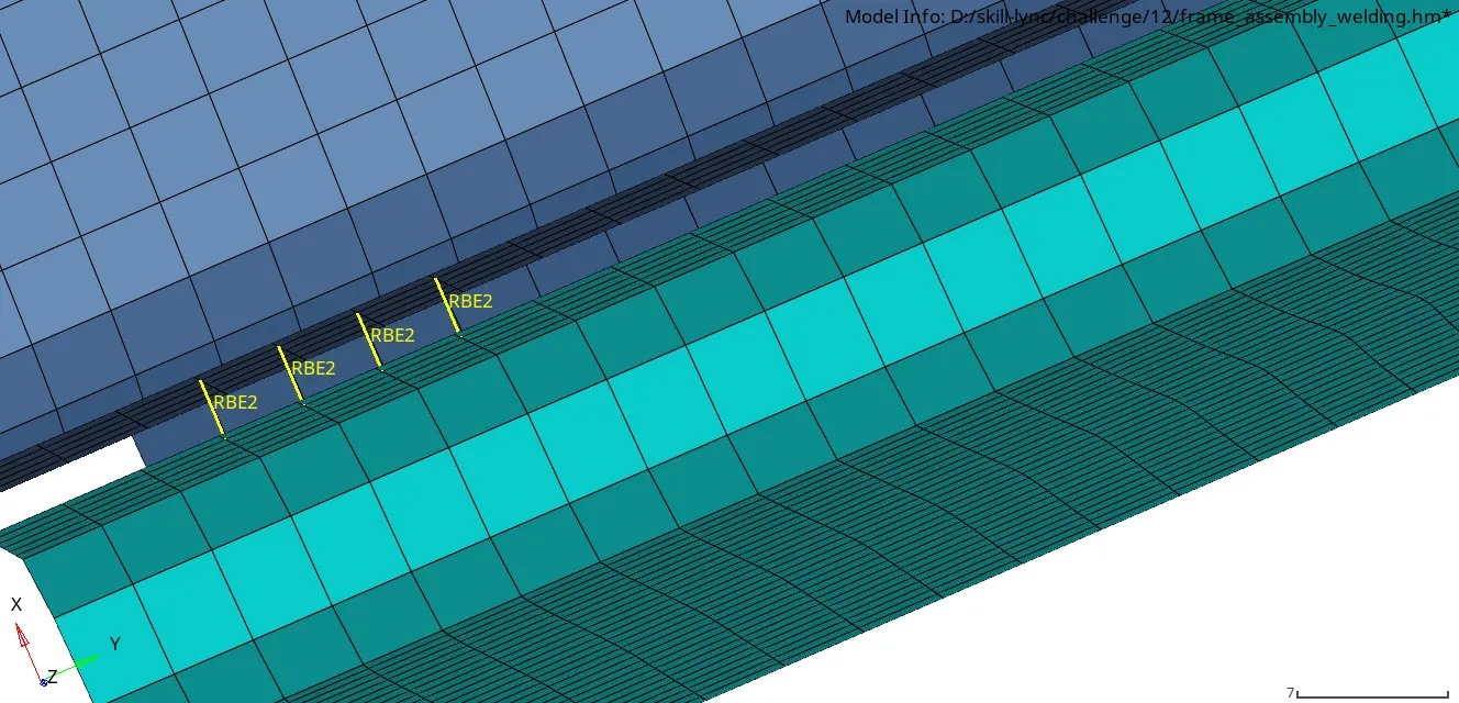
img.8 spot weld - rigid connector
left Rail 1,left Rail 2:
- now create the same connector but type will be spring.
- select 1D+spot weld+spring
- now select independent and dependent nodes and then create.
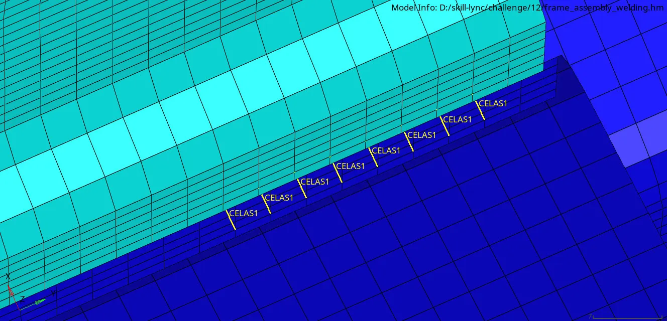
img.9 spot weld-spring connector
Reinf plate & front truss 2:
- now hide the components and then unhide these components.
- first create a connector by select[1D+connector+spot+weld]
- select tolerance as 10mm, spacing-4, layer-3, diameter-5mm and then create.
- select the nodes & components to create the connectors.
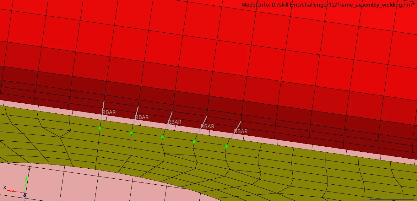
img.10 spot-weld connector
Front truss 2 & left Rail 2:
- hide the componets and unhide two components
- create bolt(CBAR) connector 1D+connector+bolt+bolt CBAR
- select tolerance-10mm, create hole if none, layer-2
- select nodes and components and then create.
- the 2D mesh do not distorted due to the connector.
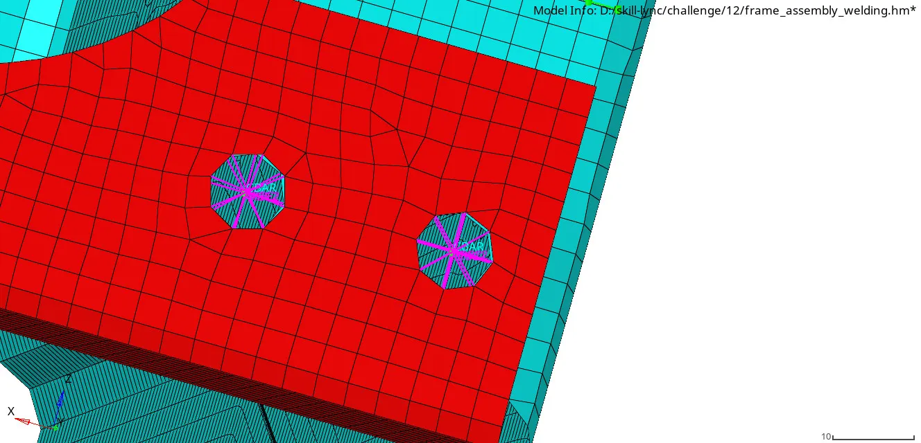
img.11 bolt CBAR connector
Front truss 2 & right Rail 2:
- hide the other parts and unhide these parts.
- now select 1D+spot weld+weld.
- now select using nodes and then select independent and dependent nodes and then create.
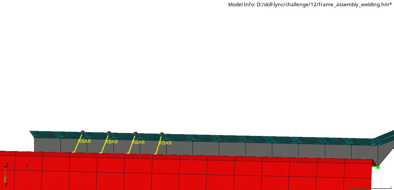
img.12 spot weld-weld connector
Right Rail 1 & rear truss 2:
- now unhide these components and hide others.
- To create the spot weld(spring) connector, select 1D+spot weld+spring
- now select independent and dependent nodes and then create.
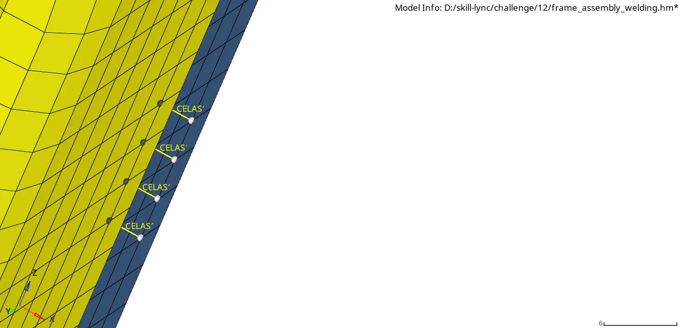
img.13 spot weld- spring
left Rail 1 & rear truss 2:
- hide all parts, now unhide these two components.
- now to create seam+hexa(adhesive) connector by select(1D+connector+seam+hexa(adhesive)).
- assign tolerance-10mm, spacing-4, strip-2, coat-2 and then select node path and components.
- now create the connector.here there is no distortion in the mesh.
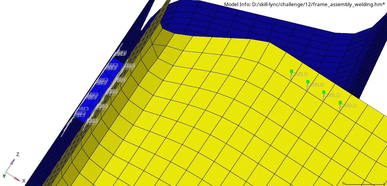
img.14 hexa (adhesive) connector
rear truss 1 & rear truss 2:
- hide the other parts and unhide these two.
- now to create the rod connector, select (1D+spot weld+rod).
- now select using nodes and then select independent and dependent nodes and then create.
- there is no distortion in the mesh.
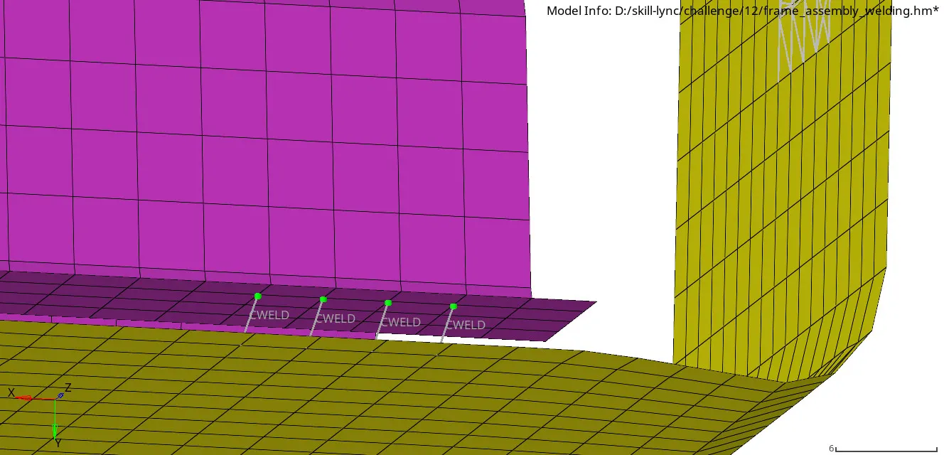
img.15 spot weld-rod connector
Result & conclusion:
- Now we created various connectors in various parts of the components to attach each other.
- Due to this challenge, now we get a idea to create the 1D,2D,3D connectors to attach the various parts of the components.
--------------------------------------------------------------