Week 2 Bevel Gear Challenge
Objective:
- To perform the grid dependency test for the bevel gear simulation for the mesh sizes 6, 5, and 4mm.
- To compare the simulations of all three cases of total deformation, von-mises stress, plastic strain.
Theory:
Grid dependency test:
Grid dependency test is to investigate how the solution depends on the grid size by running the simulation with refined mesh that is finer the mesh, higher is the accuracy of the result but with additional cost on computation time and computational power. Since solutions are interpolated at the nodes to get an approximate result, the higher the number of nodes and elements higher is the computational time and power required to complete the simulation. So, the grid dependency test helps in determining optimal mesh size where the accurate result could be obtained keeping in the mind the cost of time and power. Since the result obtained are approximate, Refining the mesh further would result in a negligible percent change is the result but only increase the computational cost.
Procedure:
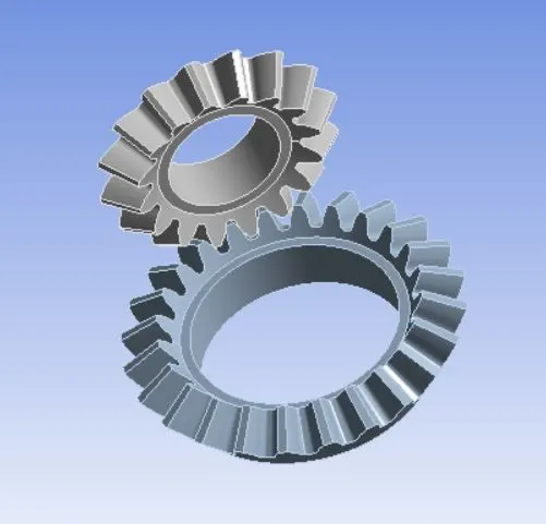
Model:
Material selection:
Open ansys>static structural>geometry>import. Now the model will be shown in the space claim window.
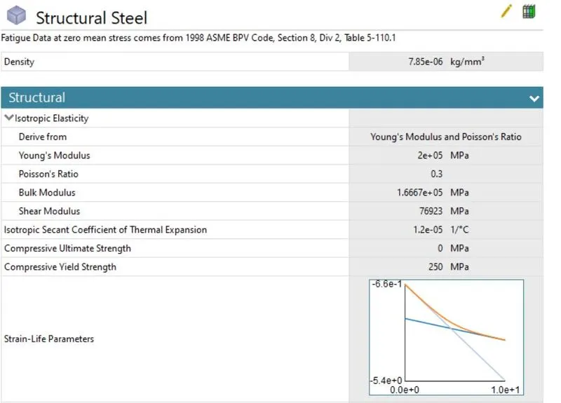
Go to material>edit>engineering sources. Now define the material or add new material. here choose the existing material structural steel.
Connections:
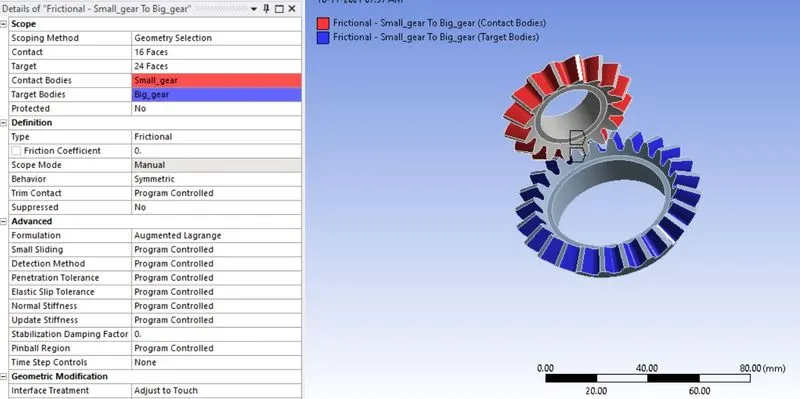
Here we need to create contact between the bevel gears. Select the contact tab. we have a contact card already. we need to change to rename by definition by clicking right click>rename by definition. Now select the tooth faces and select apply. Now assign type as frictional. Behavior as symmetric. Assign formulation as Augmented Lagrange. Treatment interface as adjust to touch.
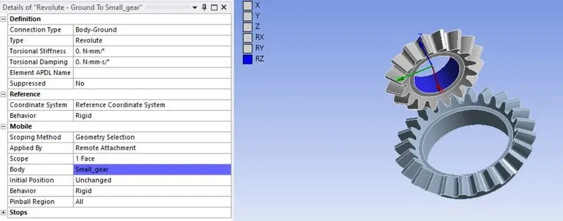
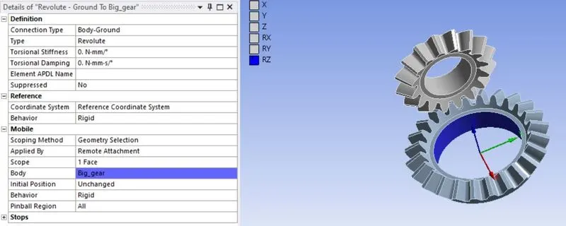
Now assign joint contact to the bevel gears. Here right clk>Joint. Now select the inner circular faces. Define connection type as Body-ground and joint type as revolute for both gears.
Meshing:
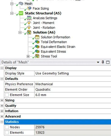
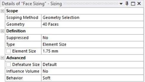
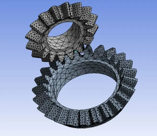
Here we need to define element size as 6mm for case-1 and 5 & 4mm for the other two cases. Now right-click on mesh>insert>sizing. Here we need to reduce the mesh size of the tooth of the gears because we need closer results over the contact area. so in the sizing tab, define element size as 1.75mm. Also, check for elements and nodes that exceed the level given in the student version.
Analysis settings:
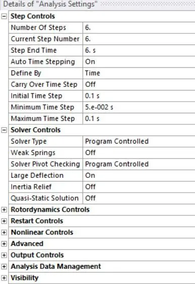
Now assign no. of. timesteps as 6 because we need to rotate the gear for 120 degrees and define auto time stepping as ON. Carry time step as OFF. Define by as time. assign large deflection tab as on. Initial time step as 0.1. Max time step as 0.1. Min time step as 0.05.
Defining Load:
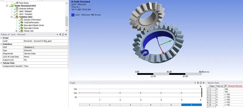
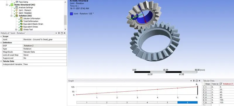
Now create a joint load for the geometry. For small gear, Right clk>insert>joint load. Now define DOF as rotation Z, Type as rotation, magnitude as tabular data. Now create tabular data as 20, 40, 60, 80, 100, 120. For big gear, define DOF as rotation Z, Type as moment, magnitude as tabular data. Now create tabular data as 100N/mm.
Defining Output results:
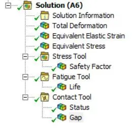
Now define outputs for the geometry using solution>right clk>insert>Total deformation, Von mises stress, von-mises strain, Contact tool, fatigue tool(life), stress tool(safety factor).
Results:
Total deformation:
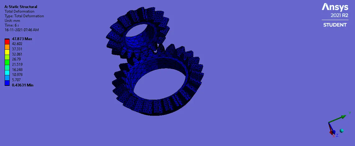
Case-1_mesh_6mm:
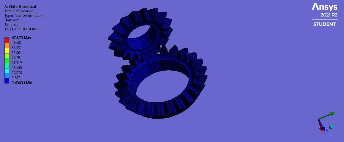
Case-2_mesh_5mm:
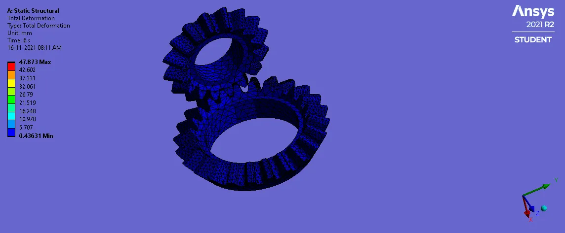
Case-3_mesh_4mm:
Von mises stress:
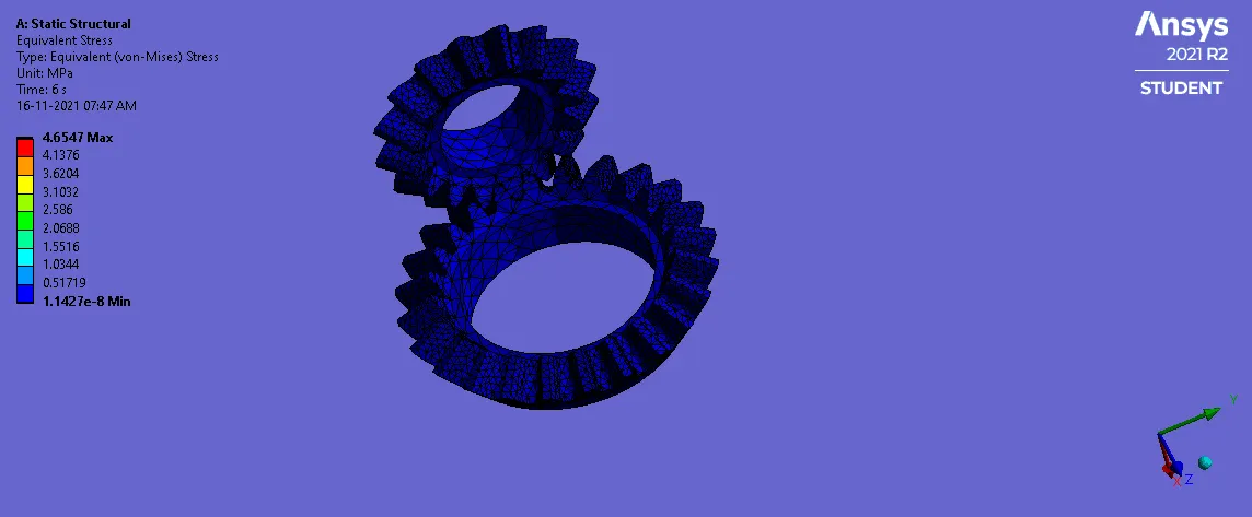
Case-1_mesh_6mm:
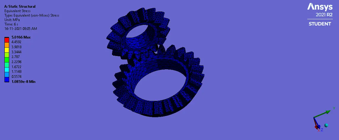
Case-2_mesh_5mm:
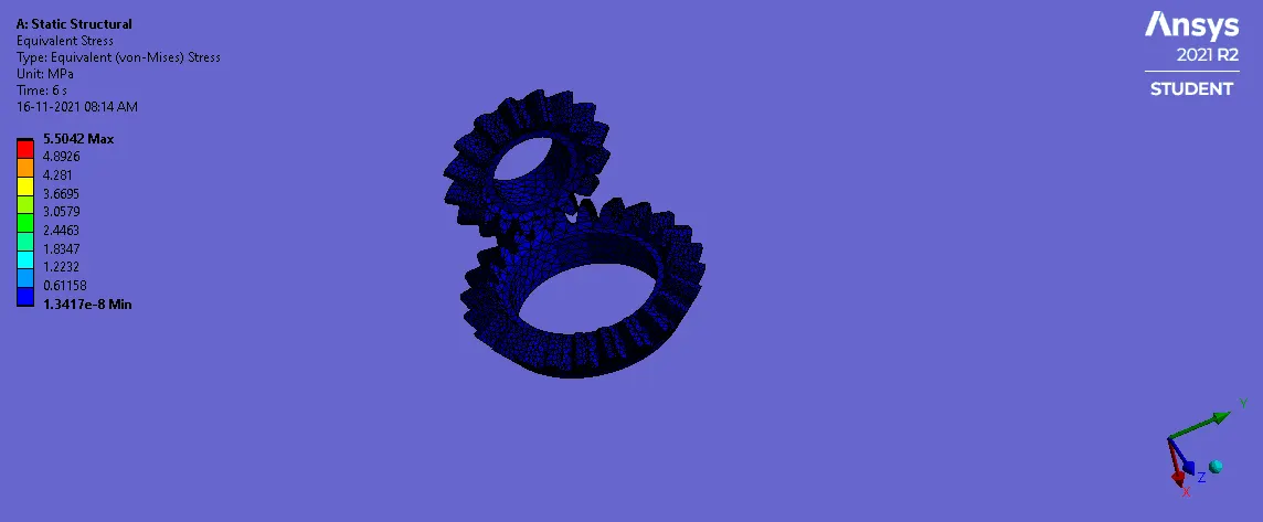
Case-3_mesh_4mm:
von-mises strain:
Case-1_mesh_6mm:
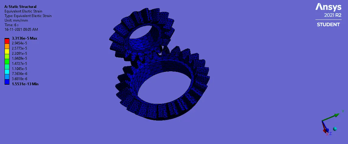
Case-2_mesh_5mm:
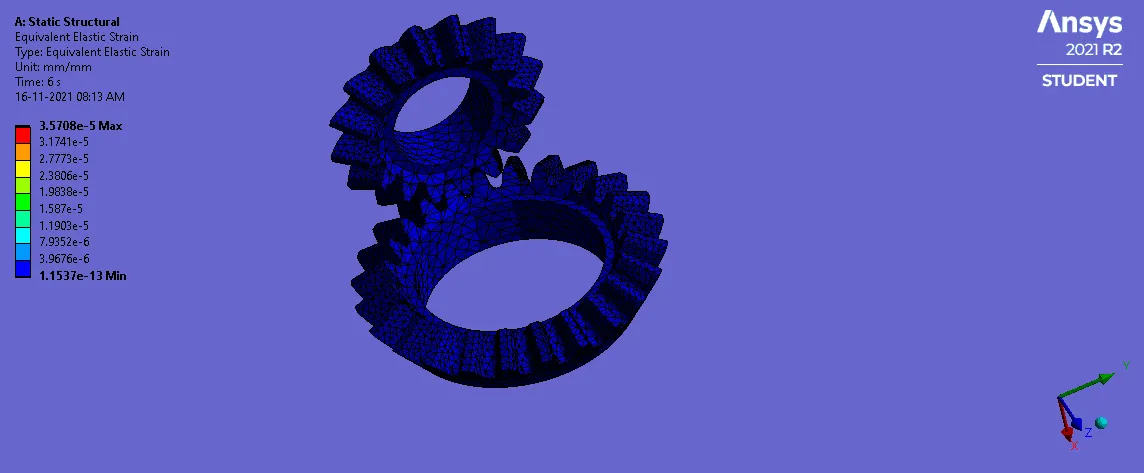
Case-3_mesh_4mm:
Comparison of results:
| Cases/parameters | Mesh_6mm | Mesh_5mm | Mesh_4mm |
| Max deformation (mm) | 47.873 | 47.873 | 47.873 |
| Max stress (Mpa) | 4.65 | 5.02 | 5.50 |
| Max strain (No unit) | 2.03e^-5 | 3.31e^-5 | 3.57e^-5 |
Here we have performed mesh with different element size for each case. The maximum deformation was induced at 47.873mm in all three cases. The maximum stress was induced at 4.65MPa in case-1 (mesh size 6mm). When we lower the element size, the results may get vary. The maximum stress for element size 5mm was induced at the tooth of the gear on 5.02MPa. The maximum stress on case-3(mesh size 4mm) was 5.50MPa. The stress on case-3 is the maximum value because we had used the mesh size as 4mm. Lower the mesh the results will be closer but solver may take very large time to solve. The mesh of the model depends upon the application of the model. We can't say this case is preferable that case is preferable. Here we are not getting the accurate results of the model. We can get the approximate results over the analysis. The results depend on its applications.
Factor of safety for all cases:
Case-1:
The factor of safety=yield strength/working stress
yield strength of the structural steel=250MPa
Working stress of the model=4.65MPa
FOS=250/4.65=53.76.
We got 53.76. It is ok. the material will not fail. The standard FOS ranges from 1-5 in industries.
Case-2:
The factor of safety=yield strength/working stress
yield strength of the structural steel=250MPa
Working stress of the model=5.02MPa
FOS=250/5.02=49.80
We got 49.80. It is ok. the material will not fail. The standard FOS ranges from 1-5 in industries.
Case-3:
The factor of safety=yield strength/working stress
yield strength of the structural steel=250MPa
Working stress of the model=5.50MPa
FOS=250/5.50=45.45
We got 45.45. It is ok. the material will not fail. The standard FOS ranges from 1-5 in industries.
Conclusion:
The structural steel material has been defined for the model. The model has meshed with different mesh sizes 4, 5, 6mm. The contacts, loads, boundary conditions have been applied for the model for all three cases. The output results have been solved for the cases. The results are discussed above.