Pedestrian Head Impact using LS-Dyna
Objective:
To study and perform the pedestrian head impact analysis and calculate the HIC value for the below-given cases and plot the stress-strain graphs for all cases.
1. Simple head model impacting on the rigid wall.
2. Pedestrian child head dummy model impacting on the rigid wall.
3. Pedestrian child head dummy model impacting on the Car hood.
Theory:
Head impact theory:
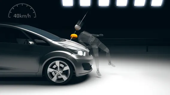
car-pedestrian accidents account for a considerable number of automobile accidents in industrialized countries. Head injury continues to be more concerned in Automobile impacts. Because the head is the most seriously injured part in many collisions including in pedestrian automobile collisions. Head injuries are the most common cause of pedestrian deaths in the car to pedestrian collisions. To reduce the severity of such injuries international safety committee has proposed subsystem tests in which headform impactors are impacted upon the car hood. Pedestrian protection has become an increasingly important consideration in vehicle crash safety. Pedestrian-vehicle crashes cause a significant number of pedestrian fatalities and injuries globally. Computer models are powerful tools for understanding how to reduce the severity of injuries in such crashes. Headform impactors are used to test the behavior of vehicle structures such as the hood.
In a pedestrian-vehicle impact, the kinematics and severity of pedestrian injuries are affected by the impact locations on the vehicle and body velocities after impact. Head injuries cause a serious threat to life and recovery is often incomplete. Therefore, it is most important to evaluate injury risks to the head. The objective of this project is to analyze the pedestrian kinematics in a Pedestrian-Car accident scenario and determine the Head Injury Criteria (HIC) from the head resultant acceleration, for head impacts at various locations on the vehicle hood. This analysis shows the effects of variations in pedestrian height on head impact position and on the potential head injury risk to the pedestrian.
Methodology:
The first step is to choose the vehicle and create a 3D model of the bonnet and head forms child and adult) has been created for the purpose of this study. These headforms were based on EEVC WG10. The same models are imported in Hypermesh for preprocessing. In preprocessing certain materials should be assigned to the bonnet as well as the head forms. After assigning the material and material properties proper thickness is given to models. Boundary conditions such as constraints to the bonnet are specified. FE model of headform is used in the simulation of impact to the bonnet.
Impact conditions were in accordance to them that were prescribed by EEVC WG10. The results of the headform to vehicle bonnet impact were compared to check the HIC values. The points on the bonnet are selected depending upon the impact angle as specified and the value of HIC is compared. To obtain a frame of reference for pedestrian head impact test conditions, it is necessary to know the impact points, impact speeds, and impact angles for the pedestrian heads.
Wrap Around Distance: The WAD is a good indicator of where head impacts are likely to occur on the bonnet. By use of the WAD, it can reasonably estimate where on a vehicle a child or adult pedestrian's head may impact.
Defining WAD:
Mark on the bonnet top, windscreen, A-Pillars, or roof (depending on the size and shape of the vehicle being tested) the 1000mm,1250mm,1500mm,1700mm,1800mm, and 2100mm wrap-around lines. These are the geometric traces described on the top of the bonnet by the end of the flexible tape or wire 1000, 1250,1500,1700,1800, or 2100mm long, when it is held in a vertical plane of the car and traversed across the front of the bonnet and bumper.
Head impacts:
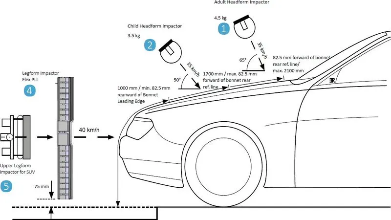
Two headforms are used to simulate this type of head impact: a child headform with a mass of 2.5 kg and an adult head form with a mass of 4.8 kg. The child headform strikes are to the front of the bonnet (wrap-around distance 1000mm to 1500mm) while the adult headform strikes are to the rear of the bonnet or beyond (wrap around distance 1500mm to 2100mm).
Six tests are conducted with each headform, based on three equal transverse zones and two impacts within each zone. One impact location is chosen for the highest injury potential, such as above engine parts, suspension mounting points, or bonnet hinges. The other is chosen to be the least injurious. Where the left and right zones have similar structures judged to be the most injurious the next worst location is chosen for one of the zones.
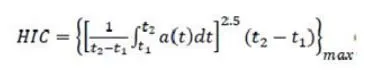
Accelerometers in the headform are used to determine Head Injury Criterion (HIC). Euro-NCAP assigns a red (poor) rating if the test results in a HIC of 1500 or more (HIC) is assumed but the deceleration curve is typically a spike of less than 8mins duration.
The Head Injury Criteria value can be calculated from the following
Procedure:
Case-1:Simple head model impact on the rigid wall.
Open the model using Open>LS-dyna keyword file. Now the model appears on the screen.
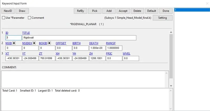
Now we need to create rigid wall for the model using model-part>Create entity>rigidwall>create>planar>N1+NL. Now select the node and create perpendicular to the z-axis and translate the rigid wall on z-axis at 15mm.
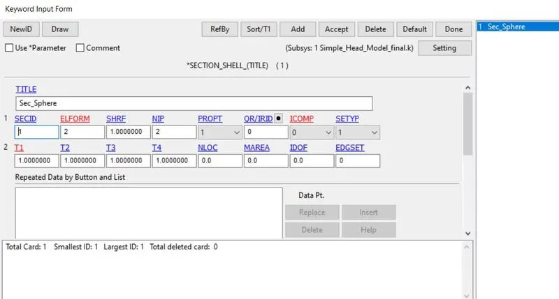
Now create section id using model-part>keywords>section>shell. now assign sec id and elform as 2 and thickness as 1mm.
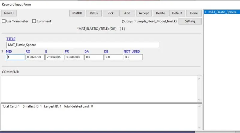
Now create the material card for the model using model-part>keywords>MAT_Elastic. Assign id, young's modulus, poisson's ratio, density values.
now create initial velocity for the simple head.
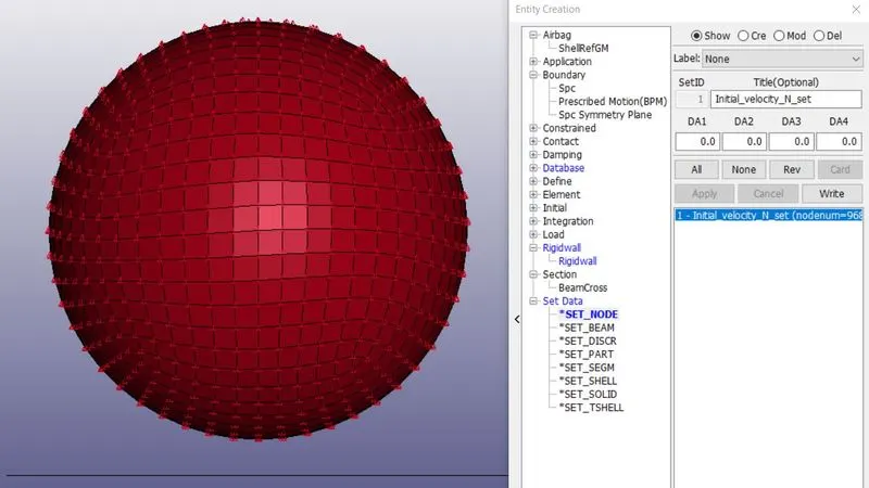
At first, we need to create a node-set for assigning initial velocity. For Node set id creation, go to Model & part>Create entity>Set data>set node>create>pick by part>assign a title and set id>apply>done. We need to assign a set id and title and then pick the nodes using the part tool. After that click apply and done.
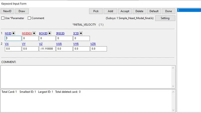
Now go to Model & part>keywords>initial>velocity. Assign value as -11.11mm/ms (40kmph) through z-axis and assign node-set id value. Now accept and done.
Creating History node for particular node:
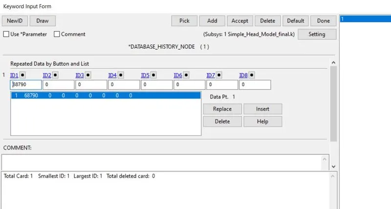
Now go to Model & part>Create entity>database>History >create>node. Now pick the node and select apply and done. Now a node was assigned.
Creating output requests:
Now we need to give output requests for the graphs we want to plot. By clicking Model & part>keywords>Database>ASCII. Here we need to assign DT for GLSTAT, MATSUM, NODOUT. Assign DT value as 0.1ms.
Creating animation output file:
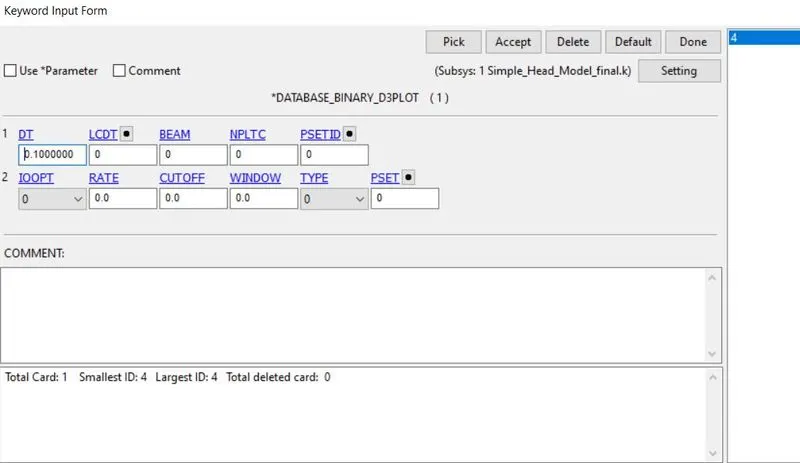
we need to give output requests for the animation. By selecting Model & part>keywords>Database>Binary D3plot. Here assign DT value as 0.1ms.
Creating EXTENT_BINARY card:
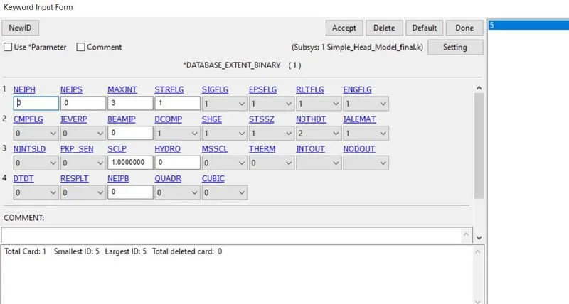
we need to give output requests for the Strain values for the model. By selecting Model & part>keywords>Database>EXTENT_BINARY. Here assign STRFLAG as 1.
Creating control termination card:
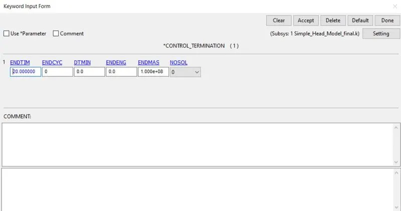
We need to put end time for the simulation for that select Model & part>keywords>Control>termination. Now assign end time as 20ms.
Case-2: Child head dummy model impacting on rigid wall.
Here we need to define a transform tool for rotating the head as per the standard degrees as 35 to 75. Here we need to open a new file. Now go to Model & part>keywords> Define>transformation. here we have parameters A1 to A7. we need to assign 010000 and A7 values as 35 degrees. assign transid as 1.
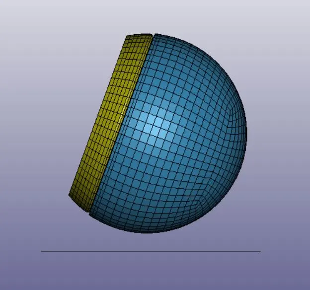
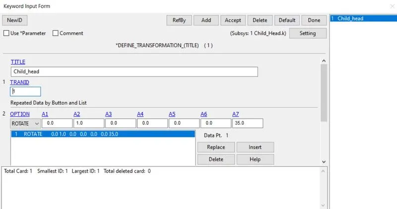
Now we need to include the pedestrian head dummy into the empty keyword file. After defined transformation, we go to Model & part>keywords>include>Transform. now select the pedestrian head dummy file. now save it with a new name. Assign transid as 1.
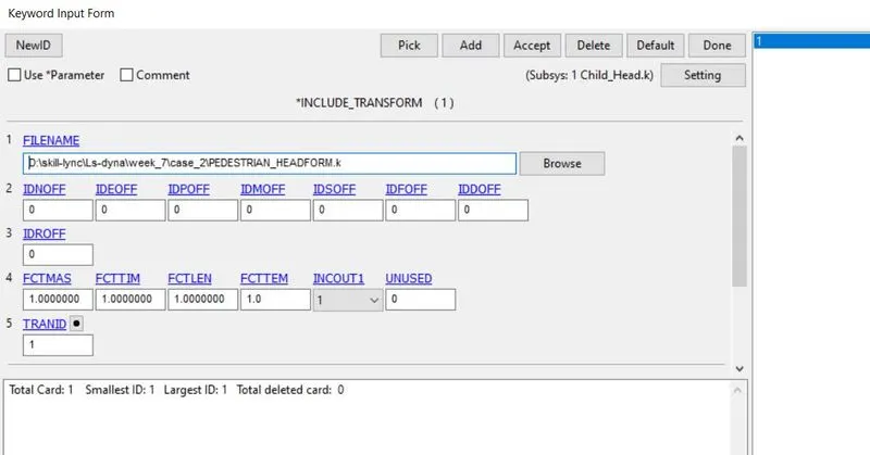
Now reopen the file using Open>LS-dyna keyword file. Now the head dummy rotated as per the standard given as 35 degrees.
Now define rigid wall for the model by model-part>Create entity>rigidwall>create>planar>N1+NL. Now select the node and create perpendicular to the z-axis and translate the rigid wall on the z-axis at 15mm.
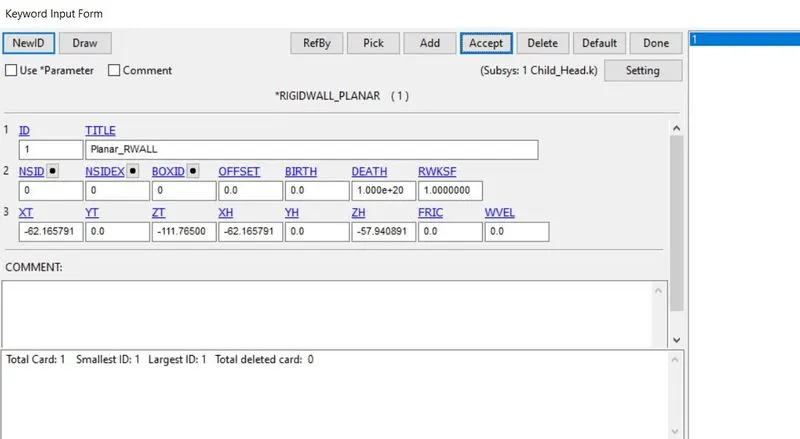
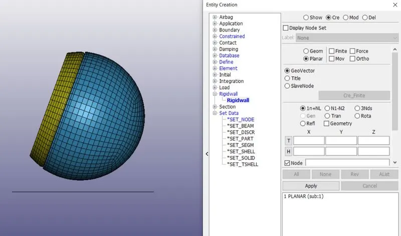
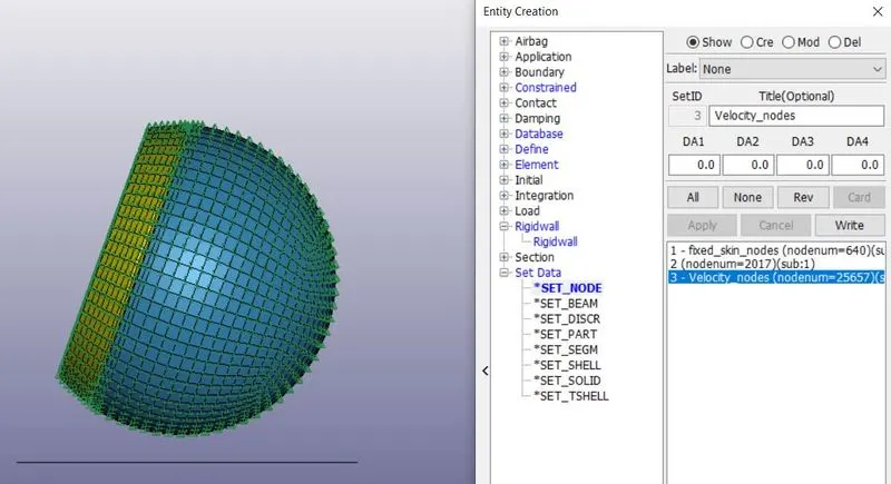
At first, we need to create a node-set for assigning initial velocity. For Node set id creation, go to Model & part>Create entity>Set data>set node>create>pick by part>assign a title and set id>apply>done. We need to assign a set id and title and then pick the nodes using the part tool. After that click apply and done.
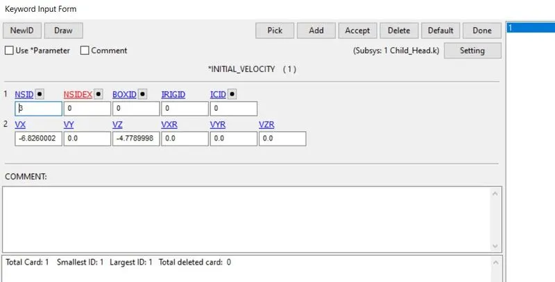
Now go to Model & part>keywords>initial>velocity. the velocity vector is in x-z plane. The Velocity value is 30kmph(8.3333mm/ms).
Vx=-8.3333cos 35=-6.826 mm/ms.
Vy=-8.3333sin 35=-4.779 mm/ms.
Now assign the values.
Defining contact:
Contact card has already been assigned for the head dummy as Automatic_surface_to_surface contact for skin and skull of the head dummy.
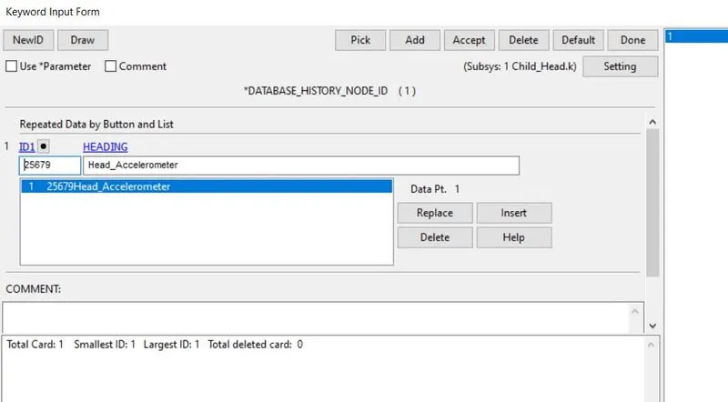
Creating History node for particular node:
Now go to Model & part>Create entity>database>History >create>node. Now pick the node and select apply and done. Now a node was assigned.
Creating output requests:
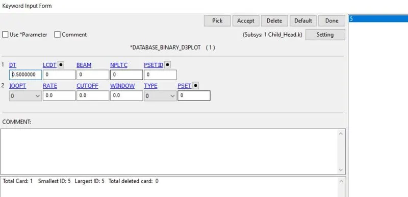
Now we need to give output requests for the graphs we want to plot. By clicking Model & part>keywords>Database>ASCII. Here we need to assign DT for GLSTAT, MATSUM, NODOUT. Assign DT value as 0.5ms.
Creating animation output file:
we need to give output requests for the animation. By selecting Model & part>keywords>Database>Binary D3plot. Here assign DT value as 0.5ms.
Creating EXTENT_BINARY card:
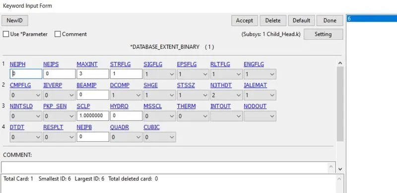
we need to give output requests for the Strain values for the model. By selecting Model & part>keywords>Database>EXTENT_BINARY. Here assign STRFLAG as 1.
Creating control termination card:
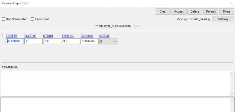
We need to put end time for the simulation for that select Model & part>keywords>Control>termination. Now assign end time as 40ms.
Case-3:Pedestrian head form impacting on the meshed hood.
Here we need to define a transform tool for rotating the head as per the standard degrees as 35 to 75. Here we need to open a meshed hood file. Now go to Model & part>keywords> Define>transformation. here we have parameters A1 to A7. we need to assign 010000 and A7 values as 35 degrees. assign transid as 1.
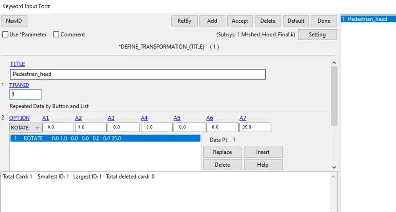
Now we need to include the pedestrian head dummy into the meshed hood keyword file. After defined transformation, we go to Model & part>keywords>include>Transform. now select the pedestrian head dummy file. Assign transid as 1. now save it with a new name.
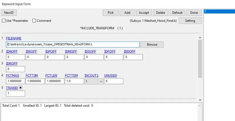
Now reopen the file using Open>LS-dyna keyword file. Now the head dummy rotated as per the standard given as 35 degrees in the meshed hood file.
At first, we need to create a node-set for assigning initial velocity. For Node set id creation, go to Model & part>Create entity>Set data>set node>create>pick by part>assign a title and set id>apply>done. We need to assign a set id and title and then pick the nodes using the part tool. After that click apply and done.
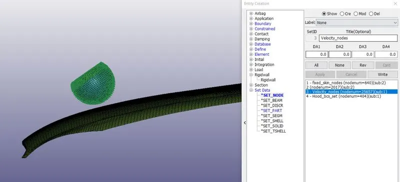
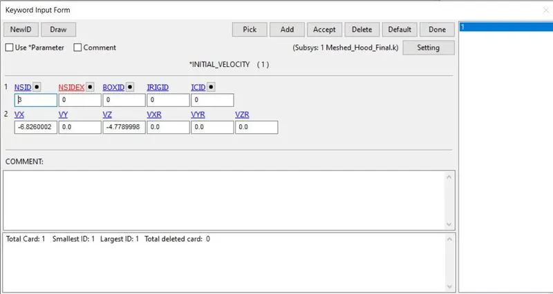
Now go to Model & part>keywords>initial>velocity. the velocity vector is in x-z plane. The Velocity value is 30kmph(8.3333mm/ms).
Vx=-8.3333cos 35=-6.826 mm/ms.
Vy=-8.3333sin 35=-4.779 mm/ms.
Now assign the values.
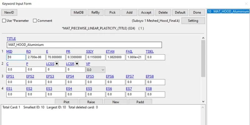
Define material card for the hood by using Model & part>keywords>MAT_024_piecewise. The material is aluminium. Assign aluminium material properties.
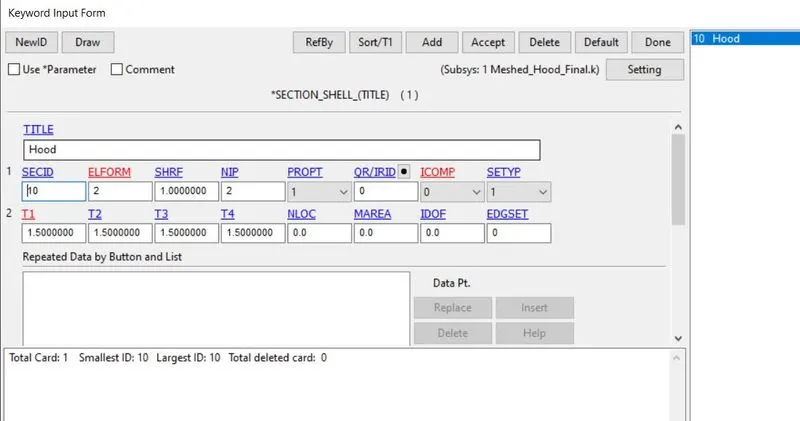
Define section id for the hood using Model & part>keywords>section. assign section id, elform as 2 and thickness as 1.5mm.
Creating contact card:
At first, we need to create a node-set for assigning the control card.
For part set id creation, go to Model & part>Create entity>Set data>set part>create>pick by part>assign a title and set id>apply>done.
We need to assign a set id and title and then pick the parts using the part tool. After that click apply and done.
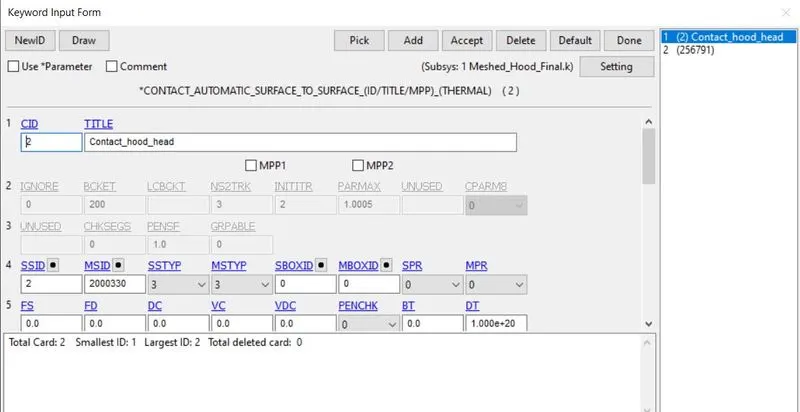
Here we need to assign surface contact for the model. So we can give slave set id and master set id to assign surface contact by clicking Model & part>keywords>Contact>Automatic_surface_to_surface. Assign the slave set id type as 2 for part set id and put SSID (Head dummy). Master set id type as 2 for part set id and put MSID (Hood). Click accept and done.
Creating boundary SPC card:
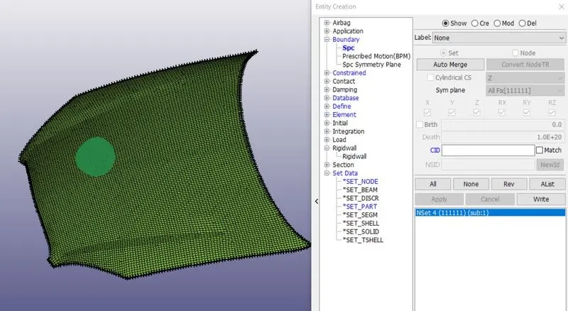
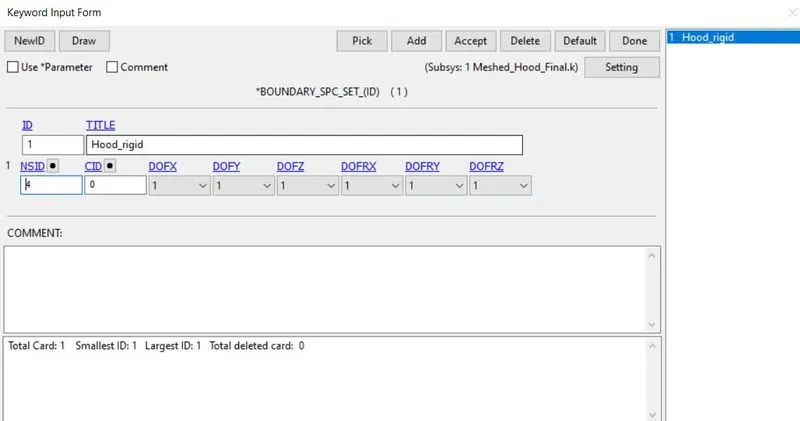
We need to create boundary SPC for the outline nodes on the hood. We need to create boundary SPC using Model & part>Create entity>Boundary>spc. Select the outer line nodes on the hood and lock all DOF's. give apply and done.
Creating History node for particular node:
Now go to Model & part>Create entity>database>History >create>node. Now pick the node and select apply and done. Now a node was assigned.
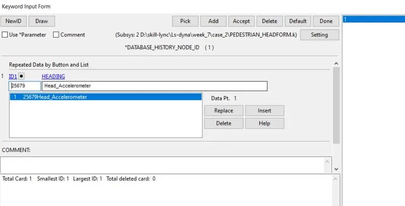
Creating output requests:
Now we need to give output requests for the graphs we want to plot. By clicking Model & part>keywords>Database>ASCII. Here we need to assign DT for GLSTAT, MATSUM, NODOUT, RCFORC. Assign DT value as 0.5ms.
Creating animation output file:
we need to give output requests for the animation. By selecting Model & part>keywords>Database>Binary D3plot. Here assign DT value as 0.5ms.
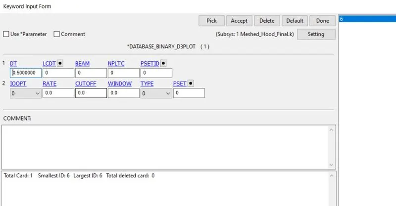
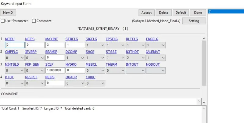
Creating EXTENT_BINARY card:
we need to give output requests for the Strain values for the model. By selecting Model & part>keywords>Database>EXTENT_BINARY. Here assign STRFLAG as 1.
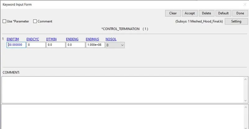
Creating control termination card:
We need to put end time for the simulation for that select Model & part>keywords>Control>termination. Now assign end time as 30ms.
Results:
Case:1-Simple head model:
Von mises stress:
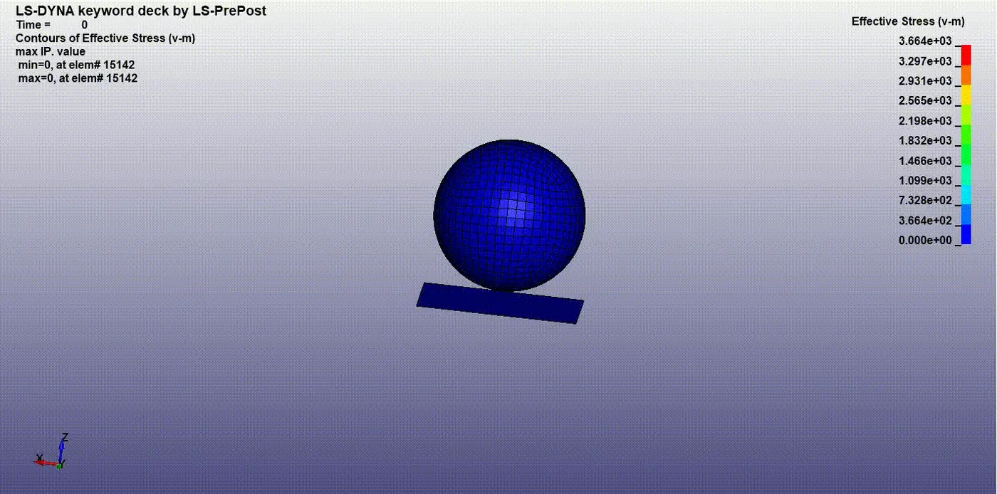
The maximum stress value induced in the model at 3.664gpa.
Effective plastic strain:
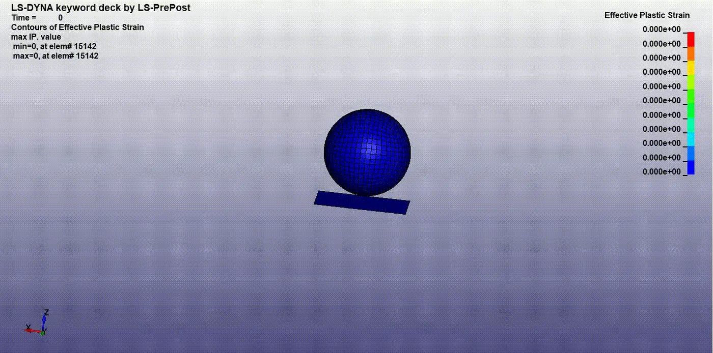
Here there is no strain value induced due to the material card we defined as elastic.
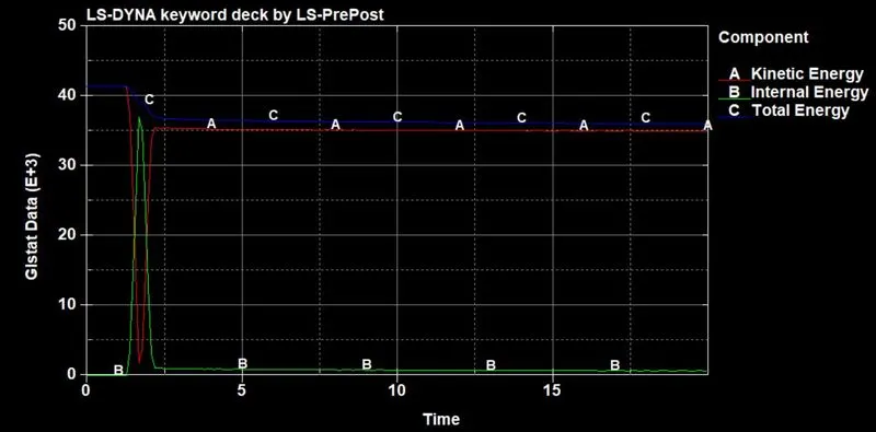
The maximum internal energy induced of 35kJ at the time of impact. At that time, the I.E absorbs the maximum K.E and converts it into internal energy.
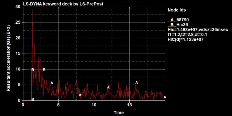
In this graph, the HIC value is taken by HIC36. The HIC(d) value was 1.123e^7 on the sphere.
Case:2-Child headform:
Von mises stress:
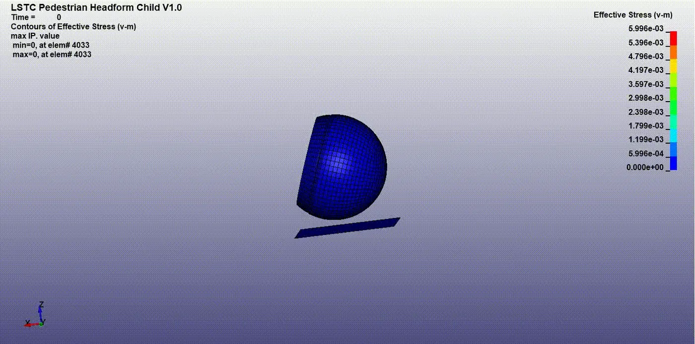
Effective plastic strain:
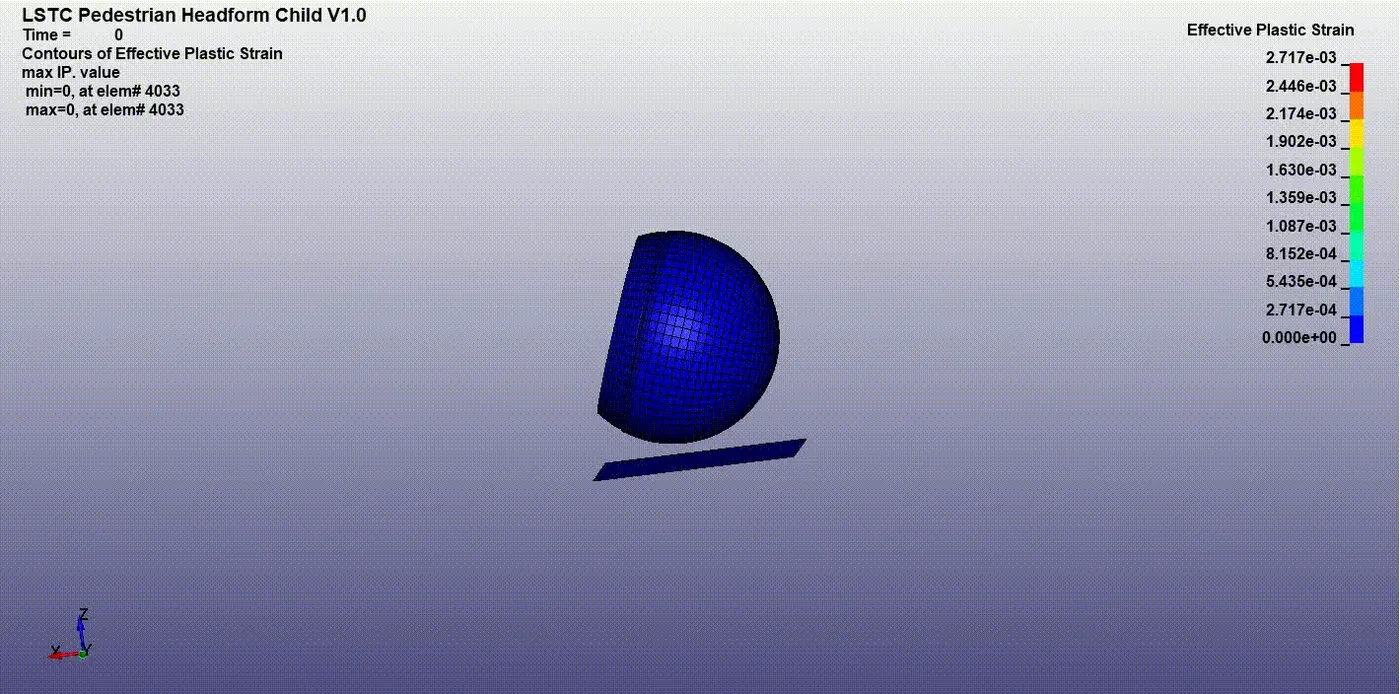
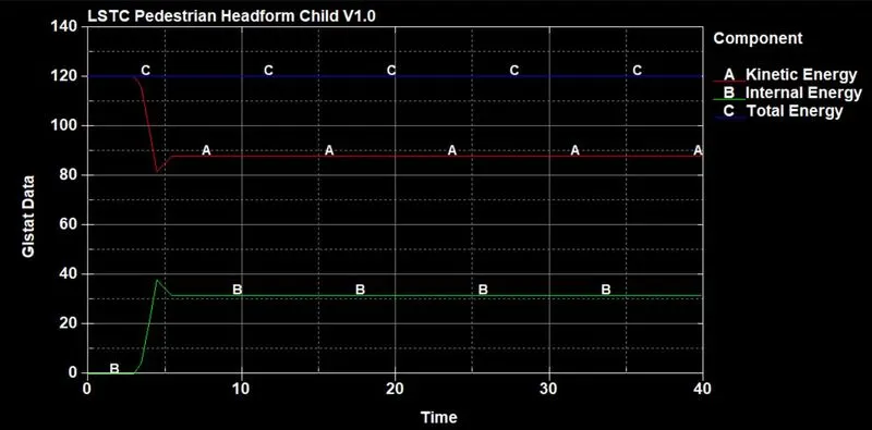
the maximum internal energy was absorbed at the time impact of 38kJ. Afte that the energy got constant throughout the simulation.
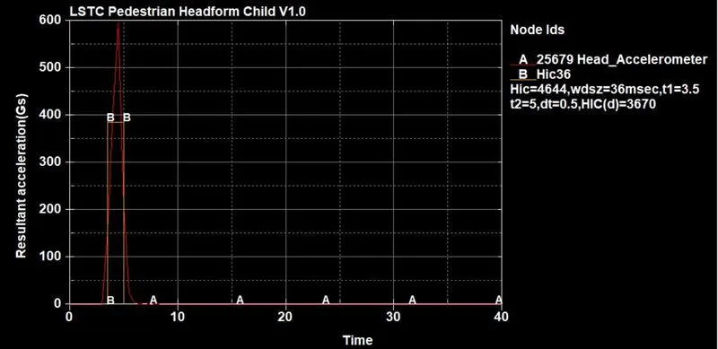
The accelerometer was placed inside the head form to calculate the maximum acceleration induced in the accelerometer. The maximum HIC(d) value was 3670. the accelerometer was helped to calculate the HIC value of the headform. After the impact, the headform got to a halt at some time after bounce back.
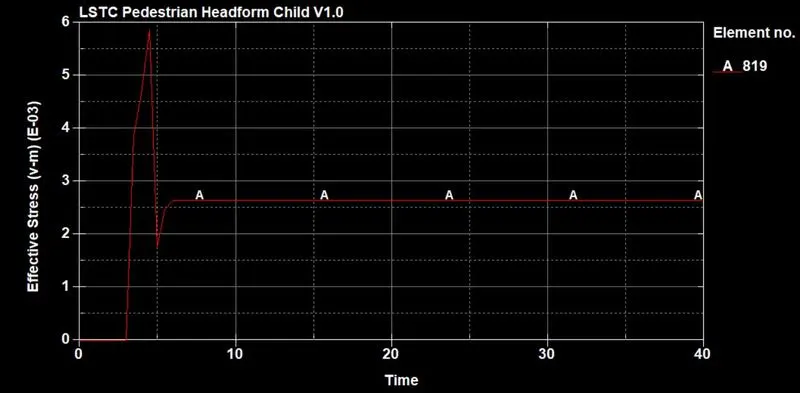
The maximum stress was induced at 5.9e^-3 Gpa on 3ms. After that, the headform bounces back due to the force acting on the headform when the impact happens.
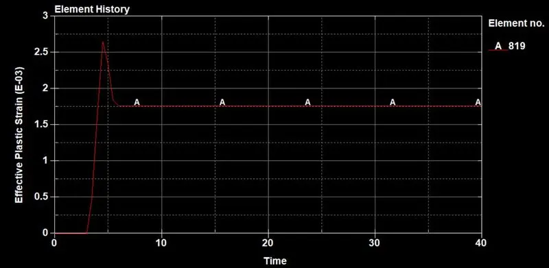
The maximum strain value was induced at 2.7e^-3. The strain rate was low in the headform because the rigidwall didn't deform, the maximum strain were induced only in headform.
Case:3
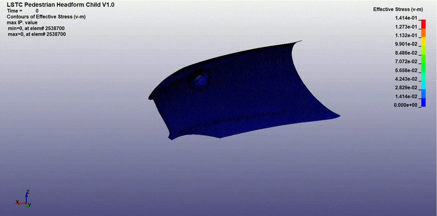
Effective stress:
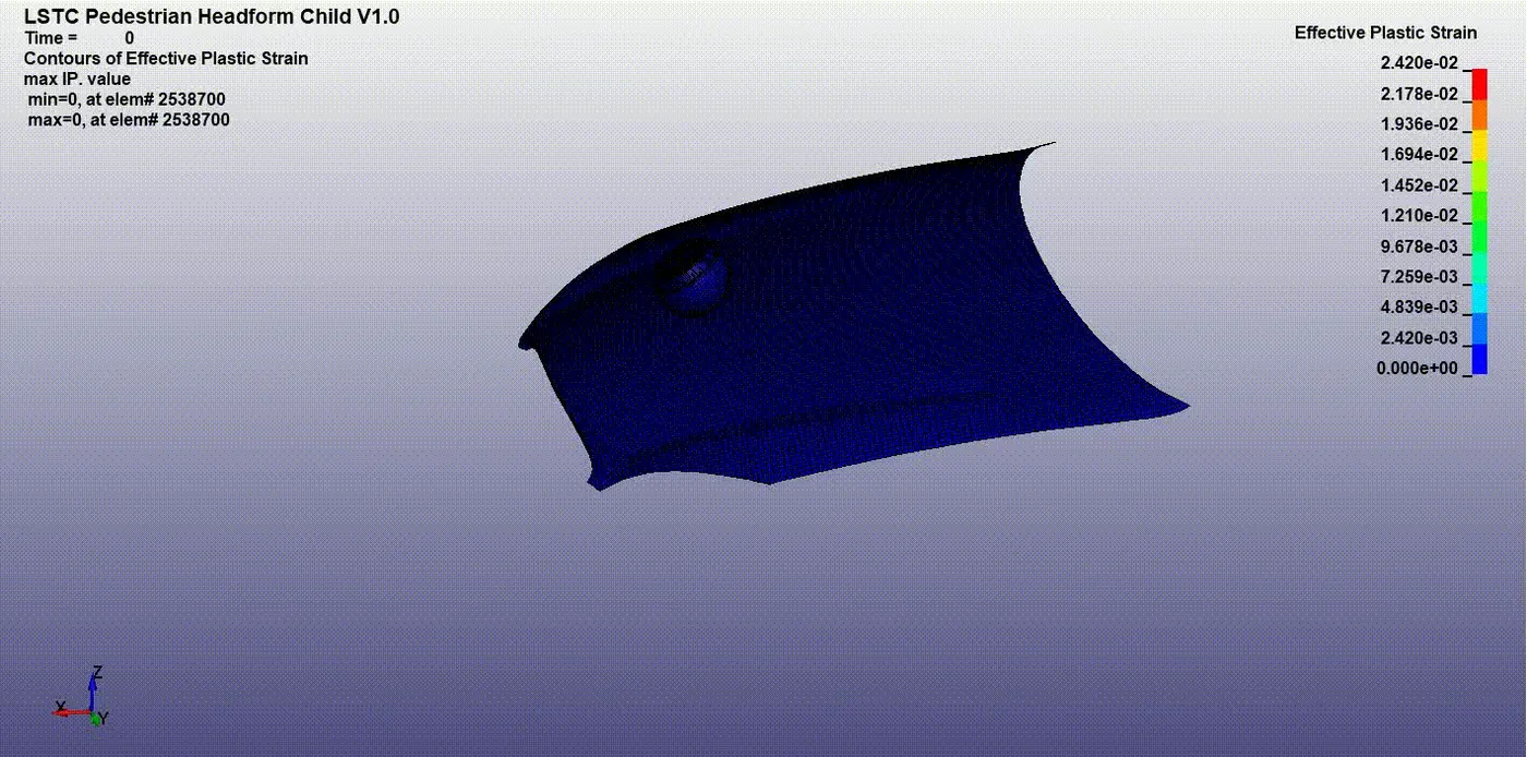
Effective plastic strain:
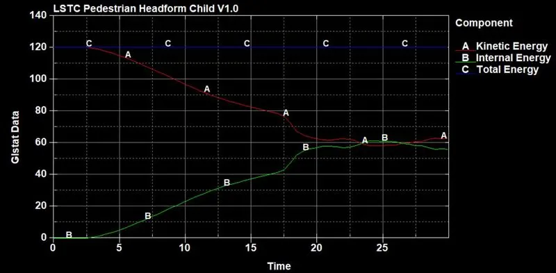
The maximum internal energy was induced of 60KJ at the time of impact. the kinetic energy absorbed by the model and turned to internal energy. the energy was transferred throughout the simulation because the deformation takes place in the hood during the impact. After that, the energy values got constant.
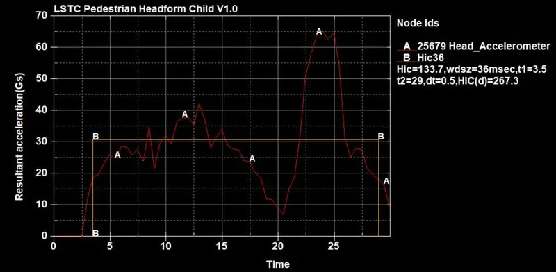
The Maximum HIC value is 133.7. The maximum HIC(d) value is 267.3. The HIC36 was taken in the graph. the Accelerometer has measured the HIC value. it was placed in the centre of the headform. The hood deforms when the headform was impacted on the hood.
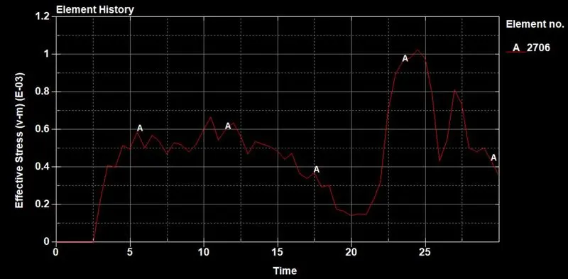
The maximum stress value was induced at 1e^-3 Gpa at 23ms. The stress got maximum due to the impact of headform. The hood deformed maximum after the impact took time.
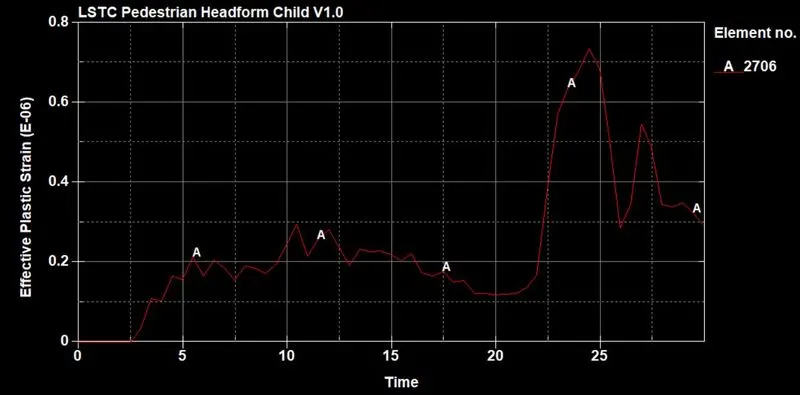
The maximum strain value was 0.7e^-6. It was very low when compared to above both cases.
Conclusion:
The given child headform model was analyzed with different kinds of cases and the results were compared with all cases. The HIC values were taken on the graph and compared with all the cases.