Week 2 Railwheel and Track
Objective:
- To perform the static structural analysis on the rail wheel simulation with different bearing loads as 100KN and 500KN.
- To compare the simulations of two cases of total deformation, von-mises stress, plastic strain.
- To carry out the user-defined results for both cases.
Procedure:
Model:
Material selection:
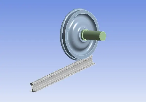
Open ansys>static structural>geometry>import. Now the model will be shown in the space claim window.
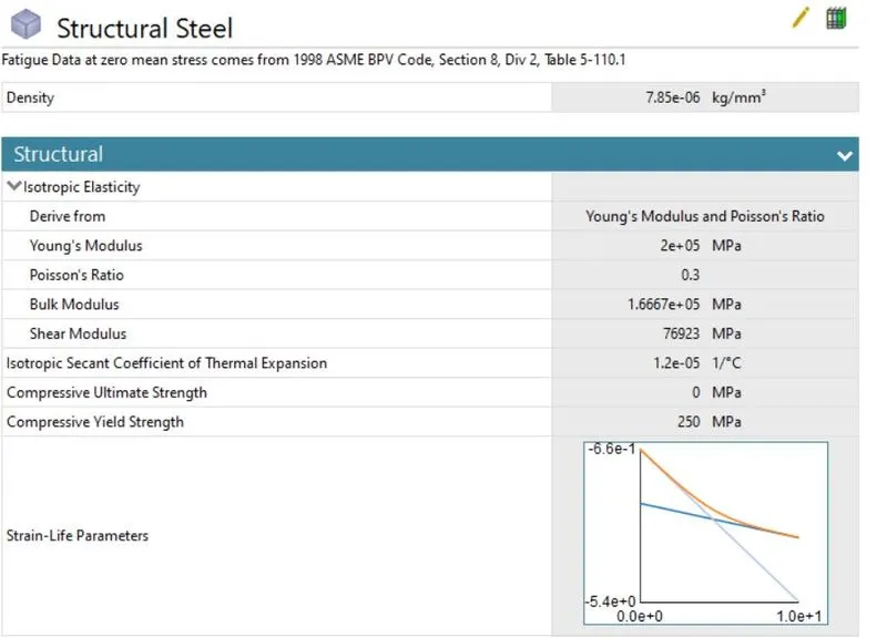
Go to material>edit>engineering sources. Now define the material or add new material. here choose the existing material structural steel.
Connections:
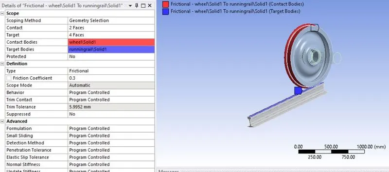
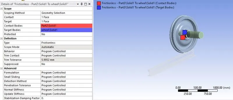
Here we need to create contact between the rail, wheel, and shaft. Select the contact tab. we have a contact card already. we need to change to rename by definition by clicking right click>rename by definition. Now select the faces need to contact and select apply. Now assign type as frictional for wheel and rail and friction coefficient as 0.3. define type as Frictionless for wheel and shaft.
Now assign joint contact to the rail, wheel, and shaft. Here right clk>Joint. Define connection type as Body-ground for all three connections.
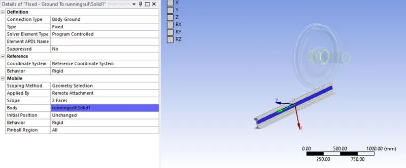
For rail, define type as fixed. select the face of the rail and apply. Here we need to fix the rail for translating the wheel over the rail.
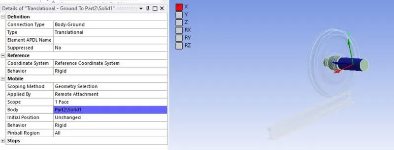
For the shaft, define type as translational. select the face of the shaft and apply.
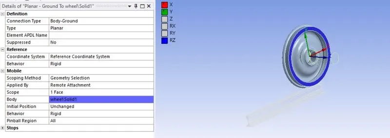
For wheel, define type as planar. select the face and apply.
Meshing:
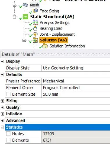
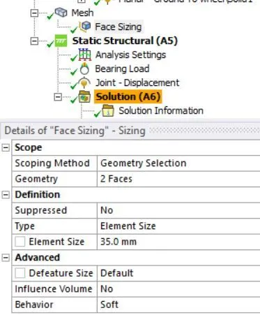
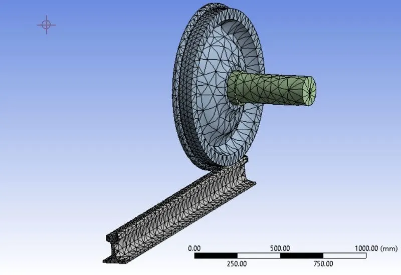
Here we need to define element size as 50mm. Now right-click on mesh>insert>sizing. Here we need to reduce the mesh size of the contact faces of the rail and wheel because we need closer results over the contact area. so in the sizing tab, define element size as 35mm. Also, check for elements and nodes that exceed the level given in the student version.
Analysis settings:
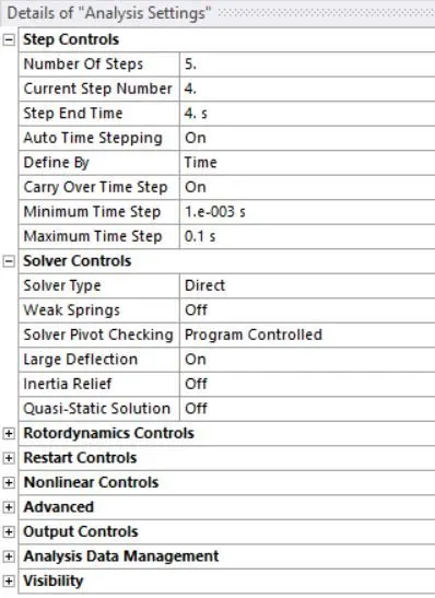
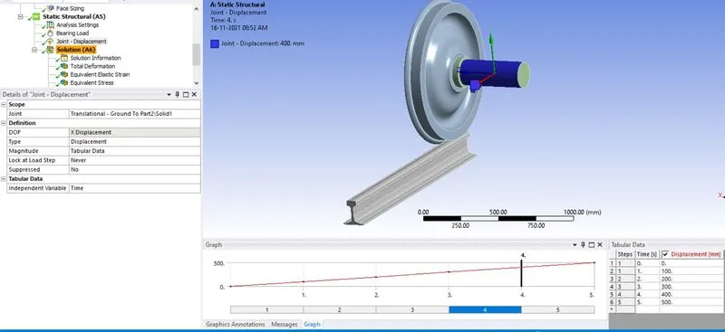
Now assign no. of. timesteps as 5 because we need to move the wheel for 500mm on the rail and define auto time stepping as ON. Carry time step as ON. Define by as time. assign large deflection tab as on. Max time step as 0.1. Min time step as 0.001. Solver type as direct.
Defining Load:
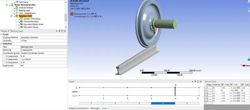
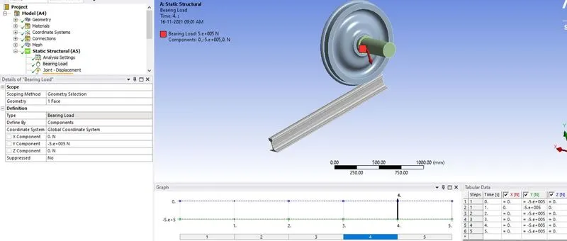
Now create a joint load and bearing load for the geometry. For wheel and shaft, Right clk>insert>joint load. Now define DOF as rotation X, Type as displacement, magnitude as tabular data. Now create tabular data as 100, 200, 300, 400, 500. For the shaft, define the type as bearing load. defined by components, Load axis as y-axis and bearing load as 100KN for case-1 and 500KN for case-2.
Defining Output results:
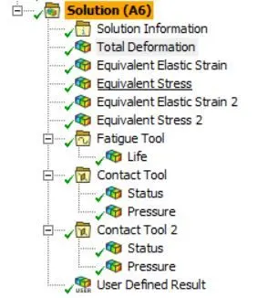
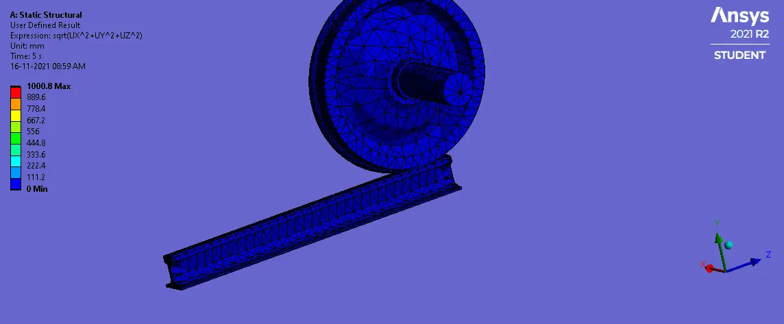
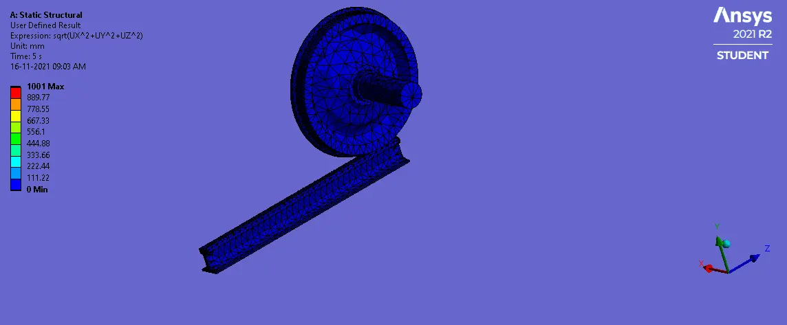
Now define outputs for the geometry using solution>right clk>insert>Total deformation, Von mises stress, von-mises strain, Contact tool, fatigue tool(life). Here we need to define user-defined output for the model. Now solution>insert>user-defined. Now define the expression as the total deformation formula. The formula for total deformation= Squareroot of the sum of all displacements (sqrt(UX^2+UY^2+UZ^2)). output unit as displacement. Now solve the model.
Results:
Total deformation:
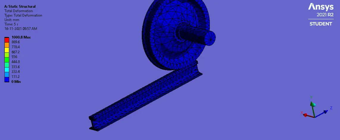
Case-1(bearing load_100KN):
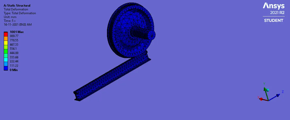
Case-2(bearing load_500KN):
Von mises stress:
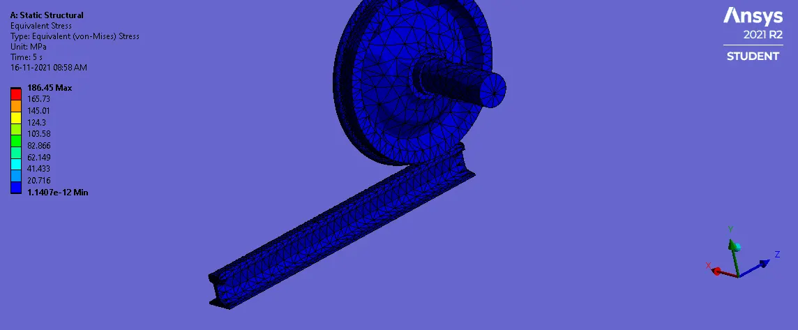
Case-1(bearing load_100KN):
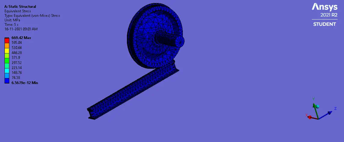
Case-2(bearing load_500KN):
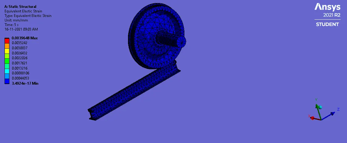
von-mises strain:
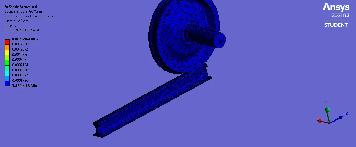
Case-1(bearing load_100KN):
Case-2(bearing load_500KN):
Fatigue life:
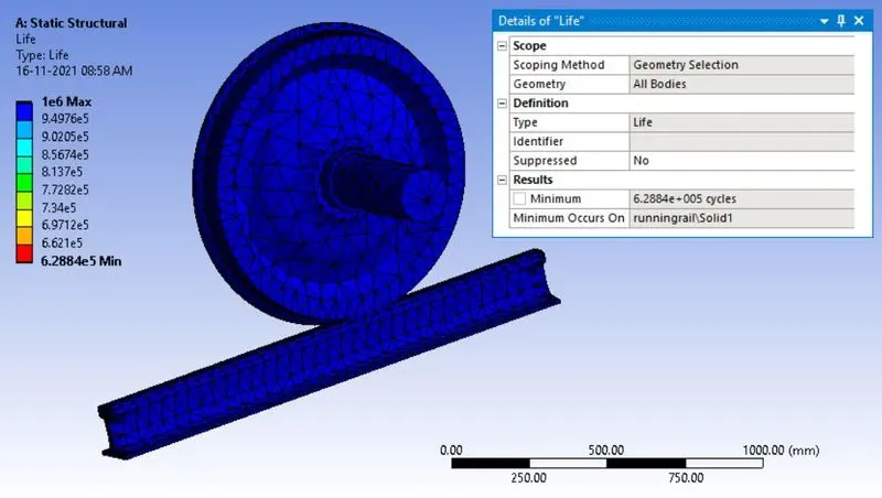
Case-1(bearing load_100KN):
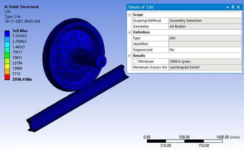
Case-2(bearing load_500KN):
User-defined result:
Case-1(bearing load_100KN):
Case-2(bearing load_500KN):
Comparison of results:
| Cases/parameters | Bearing load (100KN) | Bearing load (500KN) |
| Max deformation(mm) | 1000.8 | 1001 |
| Max stress(Mpa) | 186.45 | 669.42 |
| Max stress intensity(Mpa) | 0.0016 | 0.0039 |
| Fatigue life(cycles) | 6.2884e^5 | 2998.4 |
| User-defined total deformation results (mm) | 1000.8 | 1001 |
Discussion:
- Here we have defined two different bearing loads on the rail wheel.
- In case-1, the maximum stress was induced on the contact area of the rail and wheel at 186.45MPa. The total deformation of the model in case-1 is 1000.8mm.
- In case-2, the maximum stress was induced at 669.42MPa. The total deformation of the model in case-1 is 1001mm.
- When comparing both cases, the maximum stress value with a bearing load of 100KN is less than the yield strength of the material. so that the wheel and rail can sustain the load but in case-2 the maximum stress is higher than the yield strength and ultimate strength of the material so that the rail and wheel cannot sustain the bearing load of 500KN.
- The maximum fatigue life of the wheel and the rail with a bearing load of 100KN is 6.288e^5. So that it has infinite life over the period but for case-2 The maximum fatigue life of the wheel and the rail with a bearing load of 500KN is 2998. So that it may lead to failure over a short period of time.
- The maximum deformation of both cases is almost similar. The total deformation and user-defined results are similar. so it is fine.
- Here I will be concluding that the case-1 the rail and wheel with a bearing load of 100KN is preferable because it will long last. So it is better to go with structural steel material with a bearing load of 100KN for the rail and wheel.
The factor of safety for both cases:
Case-1:
The factor of safety=yield strength/working stress
yield strength of the structural steel=250MPa
Working stress of the model=186.45MPa
FOS=250/186.45=1.34.
We got 1.34. It is ok. the material will not fail. The standard FOS ranges from 1-5 in industries.
Case-2:
The factor of safety=yield strength/working stress
yield strength of the structural steel=250MPa
Working stress of the model=669.42MPa
FOS=250/669.42=0.34
We got 0.34. It is not ok. the material will fail because the standard FOS ranges from 1-5 in industries.
Conclusion:
The structural steel material has been defined for the model. The model has meshed and the contacts, loads, boundary conditions have been applied for the model for both cases. The bearing load of 100KN and 500 KN are applied for the cases. The output results have been solved for the cases. The results are discussed above.