Project-1- Meshing of side door plastic component using Hypermesh
Project 1: Follow the Quality Criteria and mesh the following component and assign thickness:
Objective:
To Extract the midsurfsace manually or automatic for the given side door component and mesh the component with good mesh quality and assign thickness for the component.
| s.no | quality criteria | value |
| 1 | Aspect Ratio | 5 |
| 2 | Skewness | 45 |
| 3 | Warping | 15 |
| 4 | Taper | 0.5 |
| 5 | Min. Length | 2mm |
| 6 | Max. Length | 6mm |
| 7 | Min angle Quad | 45 |
| 8 | Max angle Quad | 135 |
| 9 | Min angle Tria | 20 |
| 10 | Max angle Tria | 120 |
Now do the mesh for the given quality criteria for get a good quality mesh.
Procedure:
- First import the given side door component.
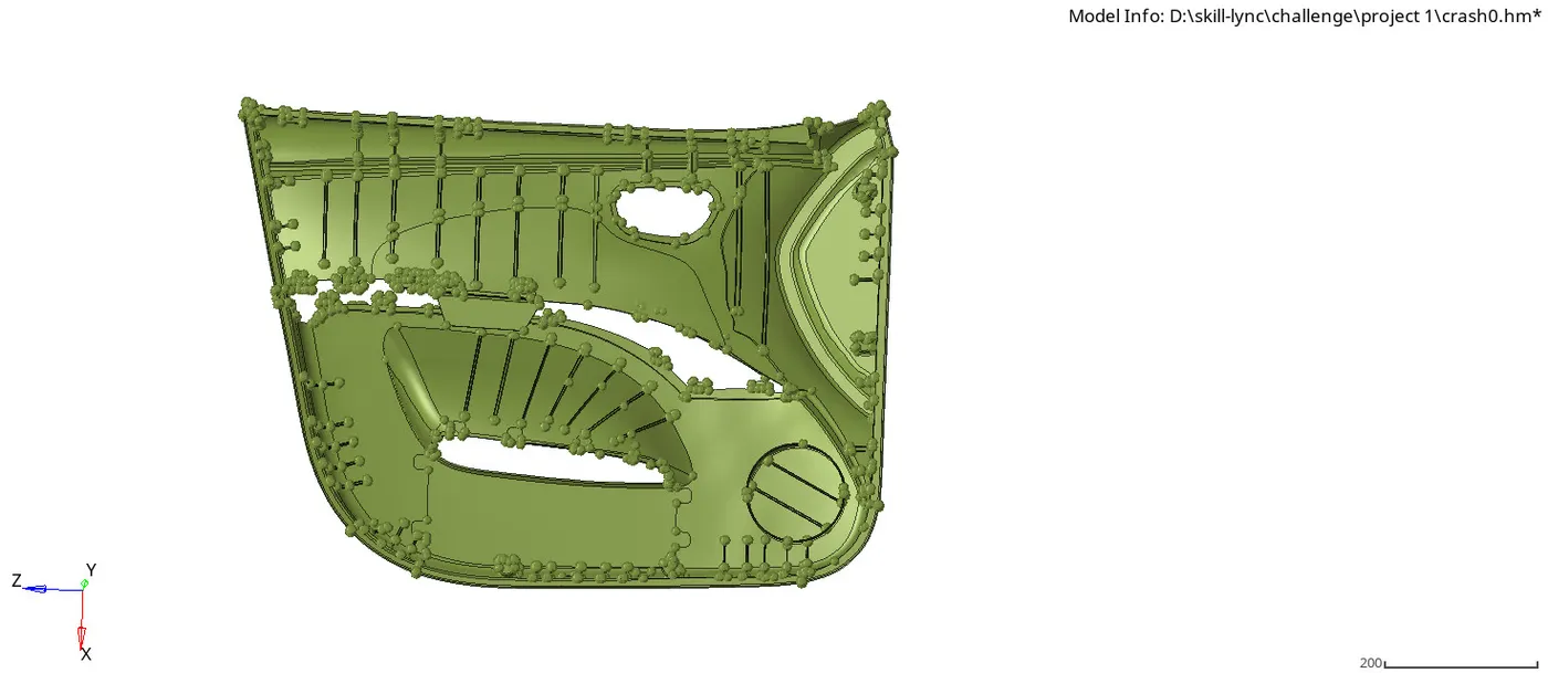
img.1 side door component
- the side door components has different componenet to attached, we have to put it in separate collector and extract the midsurface and do the mesh.
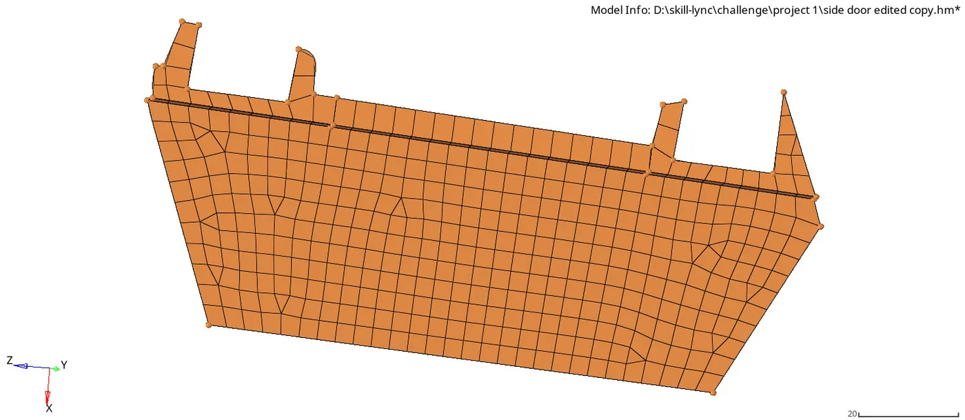
img.2 differnet component to attached with side door
- The component has different thickness in ribs and surfaces, we have to create for those different thickend surfaces and ribs by ( create+collector).
- now move the component which is connected by rivets in parent geometry and move the component to the new collector by using(tool+organise+surf+dest component+move)
- first cleanup the geometry by quick edit & surface edit tool for toggle the lines which will fail for min element size, delete the surface has glitches and recreate it.
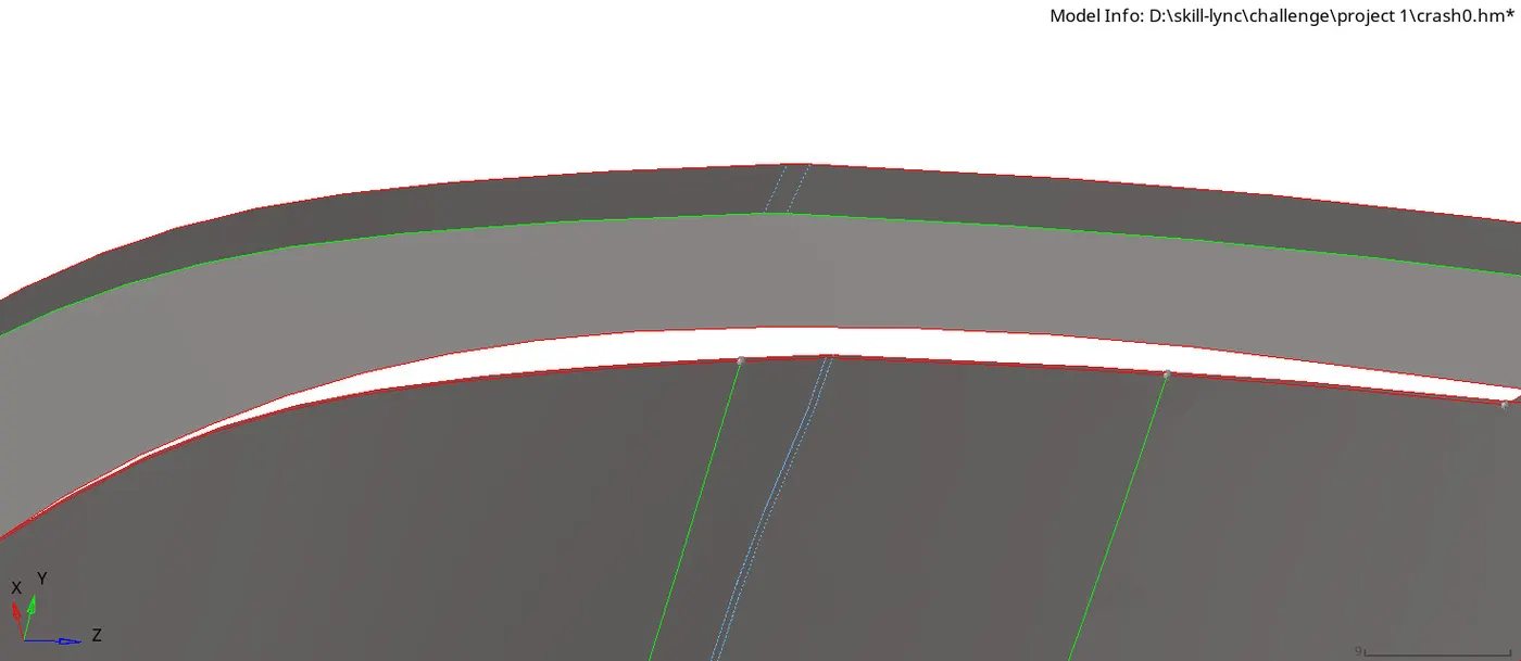
img.3 missing edge to recreate
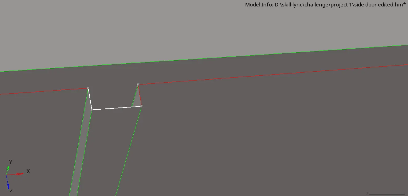
img.4 toggle the free edge lines
- now defeature the fillet which has minimum radius which will fail for min element length by (geometry+defeature+surf fillet+ assign min radii as 0.5 & max radii as 5mm), now deafeature the min fillet by this tool.
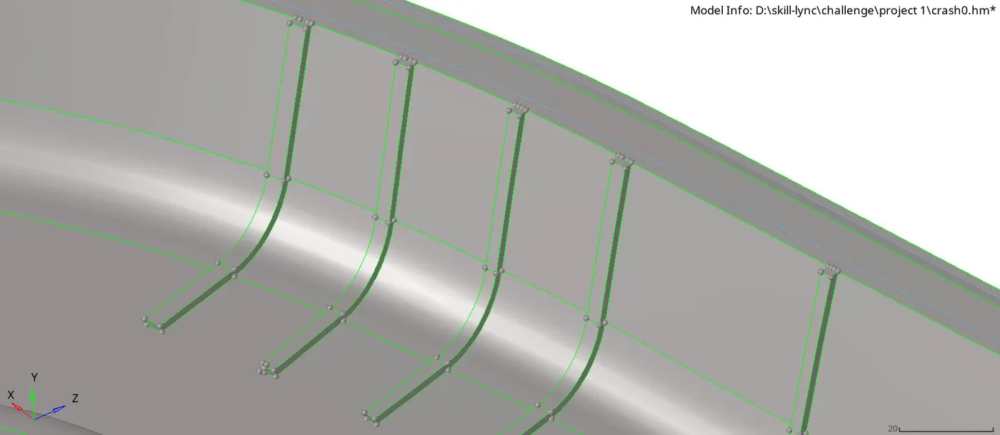
img.5 defeature the fillet
- now extract the midsurfaces for the component we will do both auto & manual midsurface here, While taking manual mid surface for all it will show errors in the surfaces, so first extract the midsurface by auto extract for the component.tool-(midsurface+auto extract+extract).
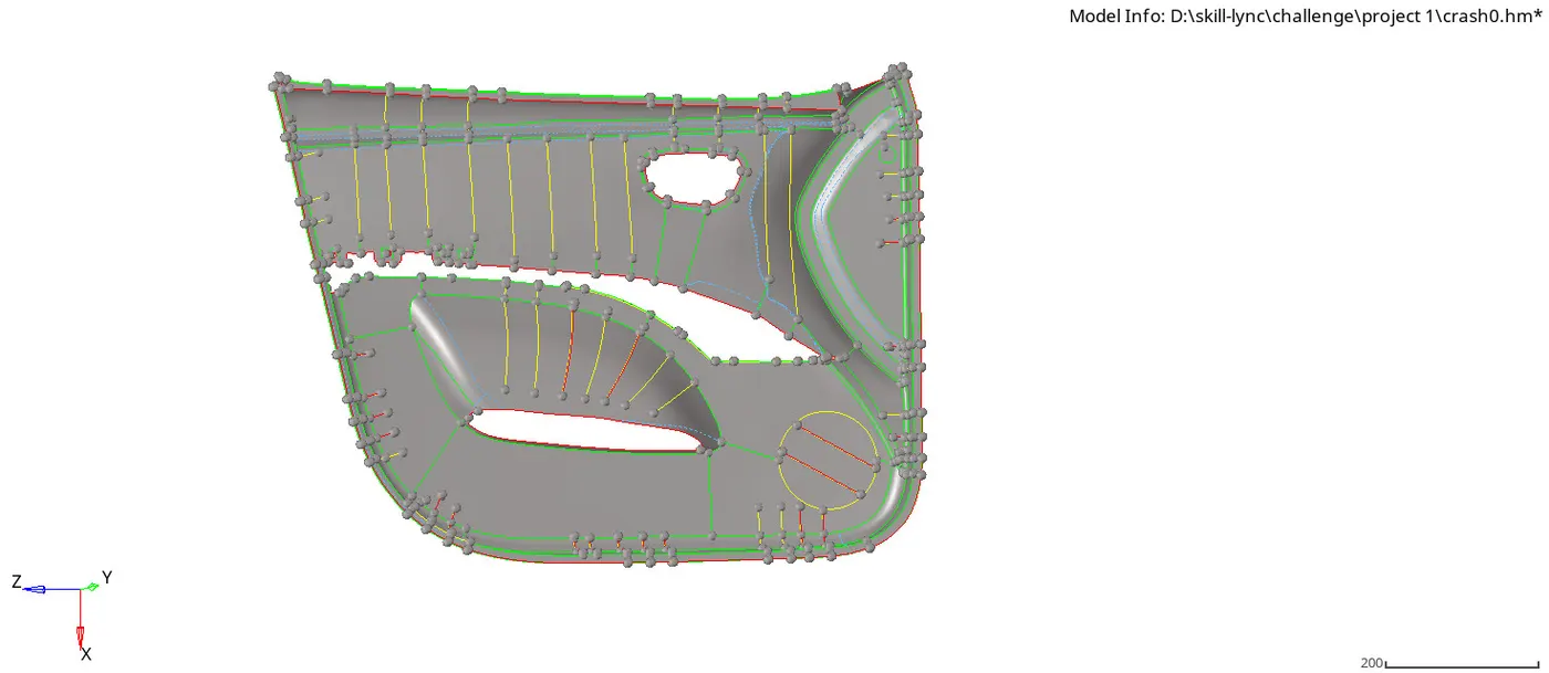
img.6 midsurface of the side door
- now create manual midsurface for the ribs because ribs has some undeleted fillet, we have to fix it manuallly and also has different thickenss of ribs in this component, so for manual midsurface use tool as (geometry+surface edit+offest+discontinuous offest+surf(duplicate)+magnitude+vector+offset).
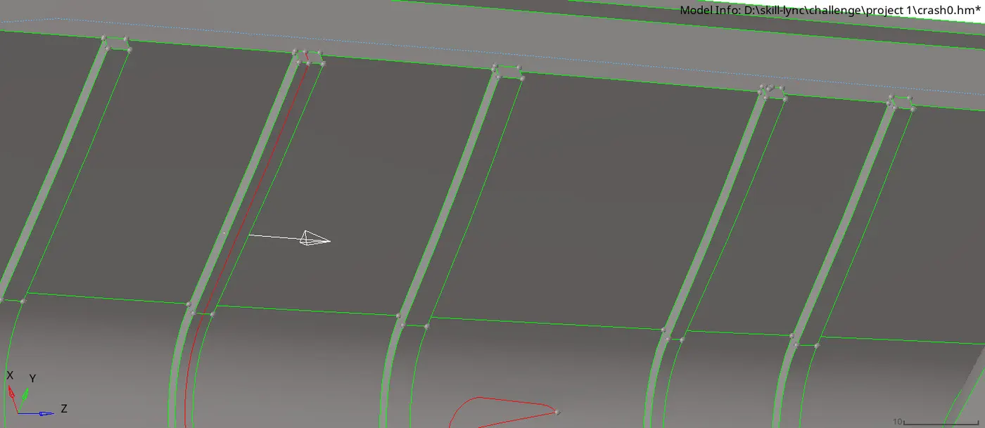
img.7 manual midsurface of the ribs
- While offset the ribs we have to check for a thickness of the ribs because it has different type of thickness, now offset the ribs as per thickness and now collect the ribs in the new collectors as per the thickness of ribs.move the ribs to the new collectors by this tool(tool+organise+dest comp+move)
- now ribs are created , the rib surfaces are hang on air due to offset, we have to fix it with the surfaces using extend tool (surface edit+extend+extend over edges+distance+create), after this trim the extend surfaces by the tool (surface edit+ trim with surf & planes) using this tool trim the extended surfaces and delete the trimmed surface by delete tool.
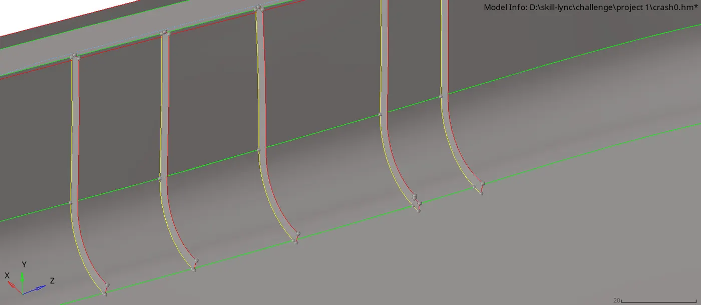
img.8 final midsurface of ribs
- After extract the midsurfce by auto and manually, now go for mesh tool, here create the mesh for the component after geometry cleanup the extract midsurfaces.
- toggle the lines by quick edit tool (quick edit+ toggle) for using this tool we can toggle the lines which are fail for min element size.
- now create the mesh by automesh tool (2D+automesh+surf+element size 4mm).
- create the mesh by surface by surface and split the surfaces to avoid maximum mesh errors.
- now start the mesh in cup holding gab surfaces and mesh it properly.
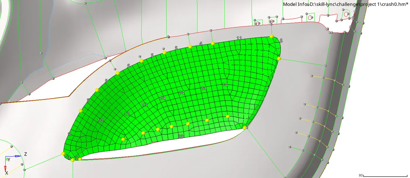
img.9 automesh of the surface as element size 4mm
- To avoid errors, follow the trias management rule and avoid rotational quads and bacl to back trias and opposite trias in the mesh.
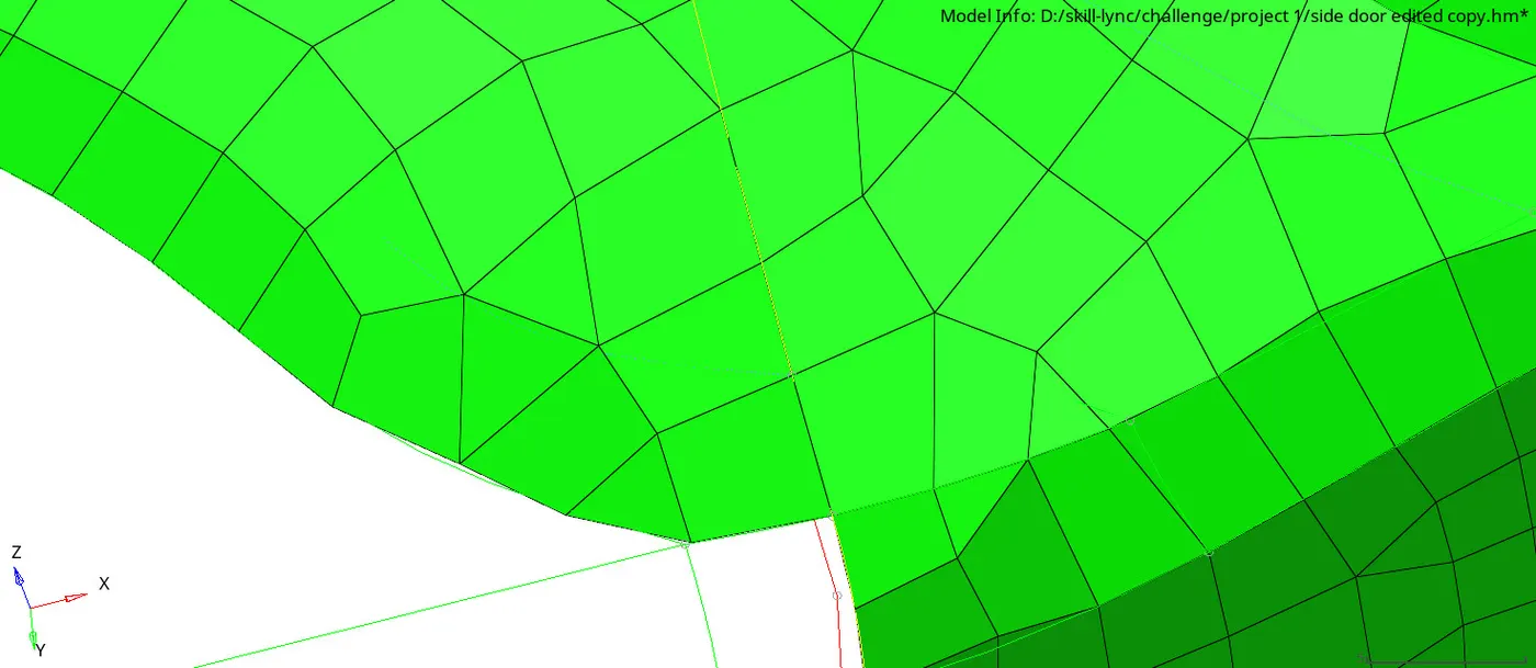
img.10 back to back trias error
- while we should face a issue called min element length failing, we can fix this with changing the distance of the elements. by tool (geometry+distance).
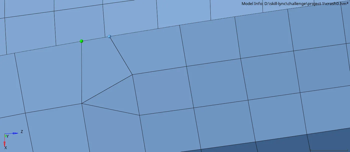
img.11 minimum length error
- we can face the warpage issue in some fillet areas, we can fix this by translate tool (tool+translate+vector) or by using autocleanup tool called element cleanup (2D+element cleanup+elements+cleanup), we should use this for few errors while using for all warpage issues we can face back to back trias error.
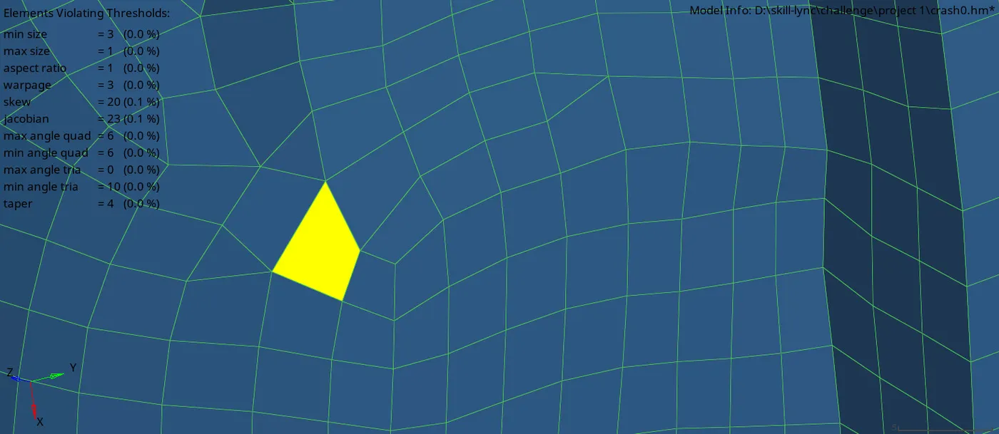
img.12 warpage error
- while meshing ribs we can face connectivity issues ,we can fix this with replace tool (2d+replace+assign nodes).
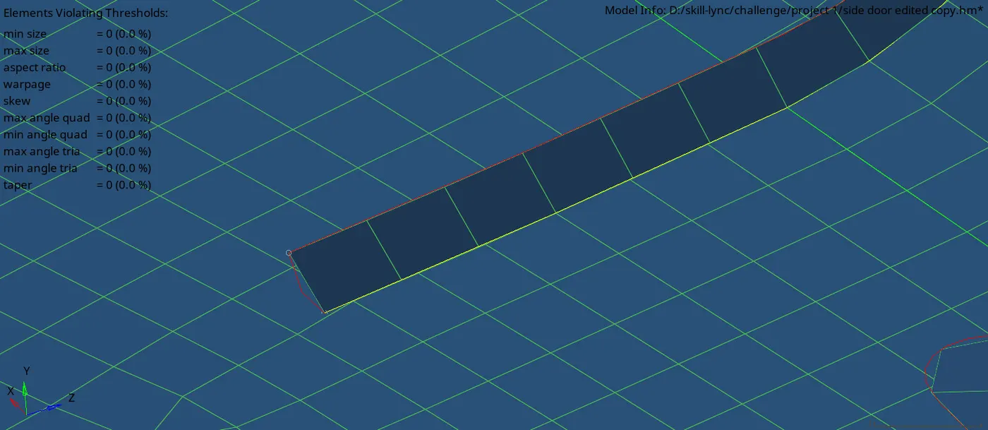
img.13 connectivity error
- now mesh the cylindrical part of the component, whwn mesh this we can face errors in connectivity,we can fix this with replace node tool above seen.,
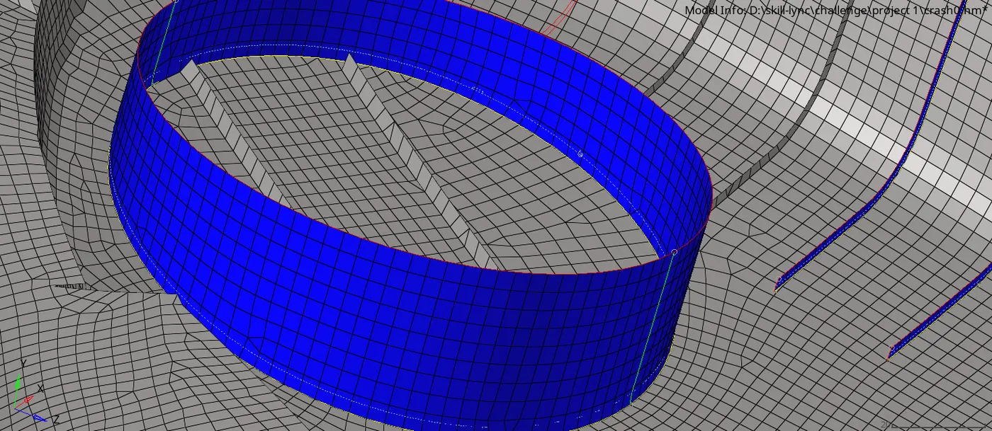
img.14 meshing of the cylindrical part
- now mesh the ribs we can get min & max size errors to fix this by distance tool or optimize the elements by using quality index tool (2d+quality index+element optimize).
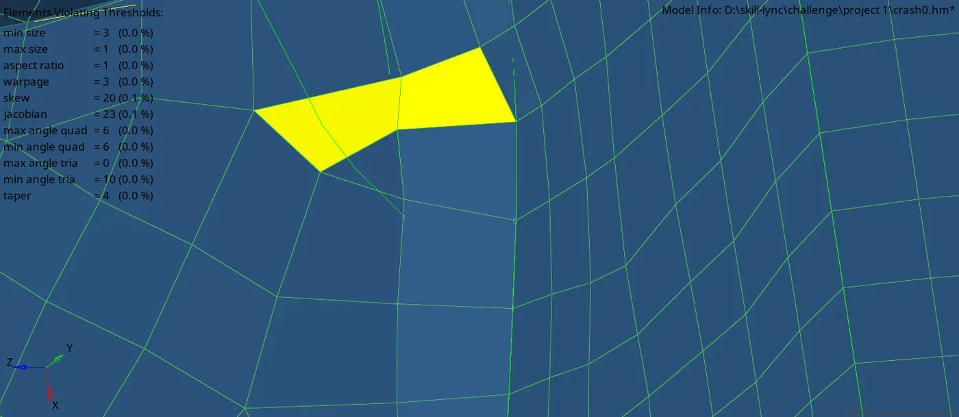
img.15 minimum length error
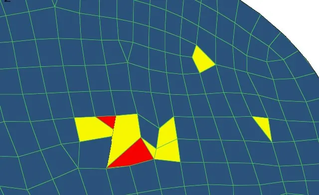
img.16 min & max element size errors
- when fixing the connectivity errors, we can face the elements are overlapping or elements are failed, when this error can be fix by edit elements tool (edit element+create or split or combine) using this tool we can edit the elements individually.
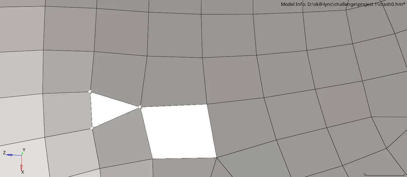
img.17 creating elements while errors
- while meshing the component,we can check for free edges in the mesh by using tool (tool+edges+elements displayed+find edges) using the find edges tool we can fix the connectivity errors easily by using replace tool.
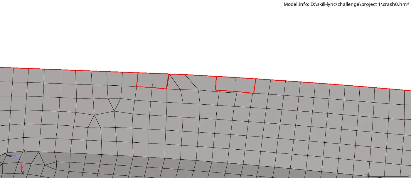
img.18 free edges error
- while mesh the ribs we can also face connectivity errors, can br rectify by replace tool.
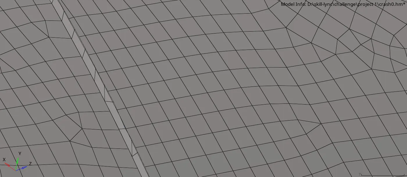
img.19 replacing nodes to fix connectivity in ribs
- when we forgot to connect the ribs while meshing, we can connect by tool mesh edit (mesh edit+ assign source as node path+destination as elements+layes as 2 or 3+select imprint).
- after this, we can easily connect the elements by replace tool, and when using this tool we can get some distortion in the mesh. we can fix this manually by quality index tool.
- while edit the distorted mesh, we can get more trias , we can fix this by drag trias tool to connect the opposite trias,(2d+quality index+drag trias), we use anothore method to solve this by remesh the elements by tool (automesh+elements+element size 4mm+mesh).
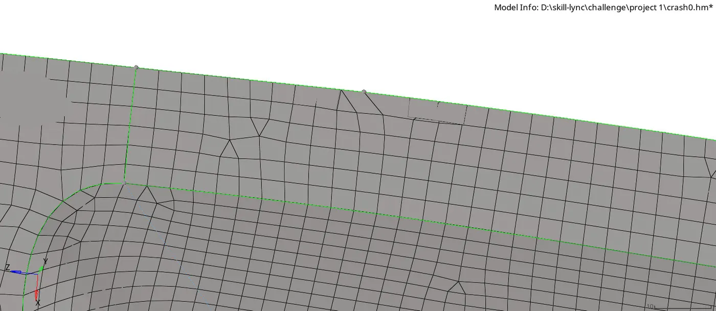
img.20 fixing trias error
- After all the errors are fixed,now we assign the property and thickness for the individual collectors by (create+property+thickess). after this assign the property for the collectors by right click the collector+select assign+assign prperty as per the collector.
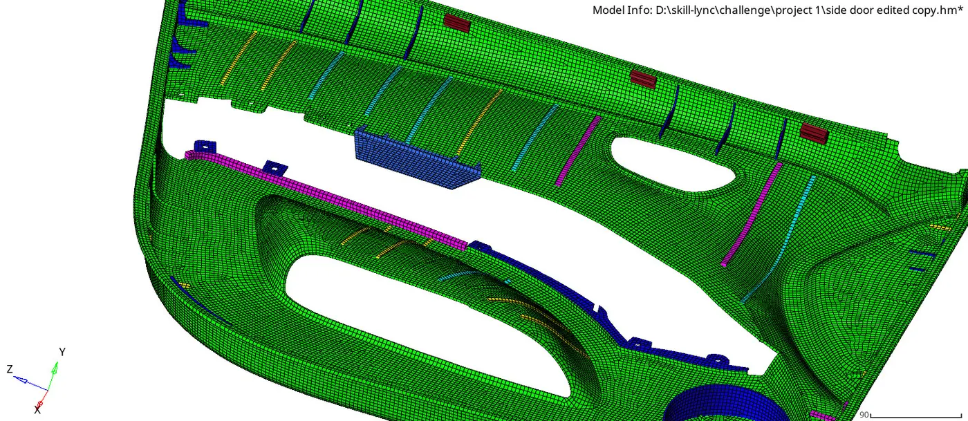
img.21 after assign property and thickness
Result & conclusion:
- The side door components are mesh by target element size 4mm and clear all quality criteria errors.The given side door component is achieved with the result of zero in quality criteria and proerty assigned and thickess were assigned for respective collectors.
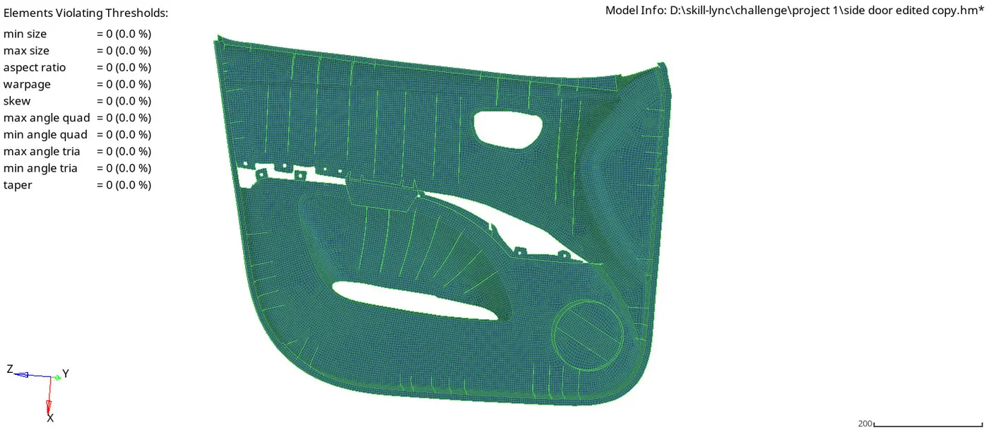
img.22 result of the mesh with zero errors
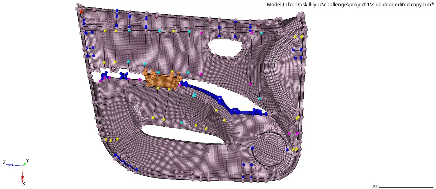
img.23 final mesh of the side door component