Project - 2 - Meshing on the suspension Assembly using ANSA
Objective:
- To mesh the given suspension assembly model as per given quality criteria in 2D and 3D mesh after fix all errors in the geometry. Deploy suitable connections for the given geometry after taking mesh for all the components and mirror the assembly.
Quality Criteria for Surface Meshing of Tyre and Rim (Element type: Tria) :
|
S.No |
Quality Criteria |
Value |
|
1 |
Target/Average length |
6.5 |
|
2 |
Minimum Length |
5 |
|
3 |
Maximum Length |
10 |
|
4 |
Skewness |
45 |
Quality criteria for Surface Meshing of Non Uniform thickness components other than Tyre and Rim (Element type: Tria) :
|
S.No |
Quality Criteria |
Value |
|
1 |
Target/Average length |
4 |
|
2 |
Minimum Length |
2 |
|
3 |
Maximum Length |
6 |
|
4 |
Skewness |
45 |
Quality Criteria for Volume meshing of all Non Uniform thickness components (Element type: Tetra Elements):
|
S.No |
Quality Criteria |
Value |
|
1 |
Tet-collapse |
0.2 |
Quality criteria for Mid surfacing of Uniform thickness part which has thickness less than 5 mm (Element type: Mixed elements) :
|
S.No |
Quality Criteria |
Value |
|
1 |
Target/Average length |
4 |
|
2 |
Minimum Length |
2 |
|
3 |
Maximum Length |
6 |
|
4 |
Aspect |
3 |
|
5 |
Warpage |
15 |
|
6 |
Skewness |
45 |
|
7 |
Jacobian |
0.7 |
|
8 |
Minimum Quad Angle |
45 |
|
9 |
Maximum Quad Angle |
135 |
|
10 |
Minimum Tria Angle |
30 |
|
11 |
Maximum Tria Angle |
120 |
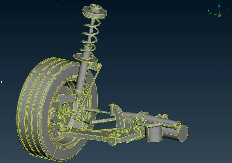
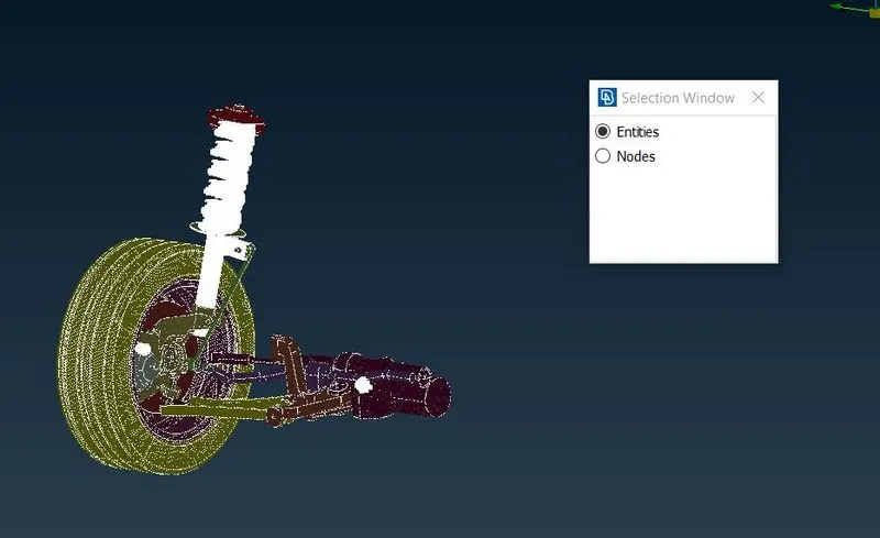
Model image:
Procedure:
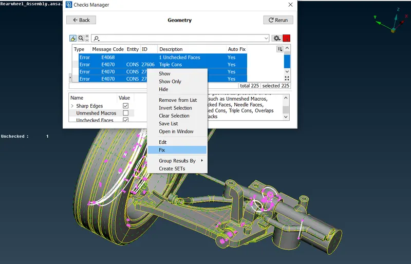
- First import the model and do topo for the geometry using faces>topo. After that we should the check the geometry which has errors and then fix all by using Checks>geometry>right click all>fix. if it has any issue after do this. we should do it manually.
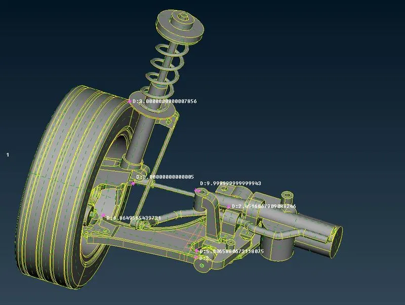
- Now use measure tool from toolbar to check the measurements for to decide which type of mesh should we carried out. As we have a rule like less than 5mm of thickness we should go for 2D shell mesh using mixed elements. if it has higher than that we must go for 3D mesh using trias and tetra mesh but we must use tetra mesh for tyres & rims.
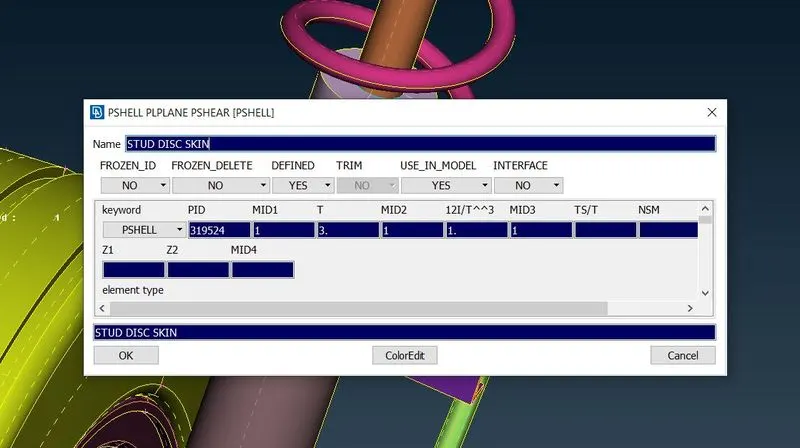
- Now we have to separate the assembly into sub components using PIDs.Assign PIDs for components. Use thickness that we measured earlier as a tool to assign PIDs using Faces>set PID. After the window appears, assign the name and thickness. If it should go for tetramesh, it doesn't had a proper thickness because its a volume mesh.
- For 2D mesh, defeature some areas to avoid minmum element fail while meshing. Take midsurface which part require 2d mesh using mixed elements.Use offset tool (faces>offset) for taking midsurface. After this, prepare the midsurface for meshing using faces>cut. Deploy the mesh using mixed elements and Check for given quality criteria. assign thickness for 2d mesh. For 3D mesh, use trias as elements and check for quality criteria before define volumes.
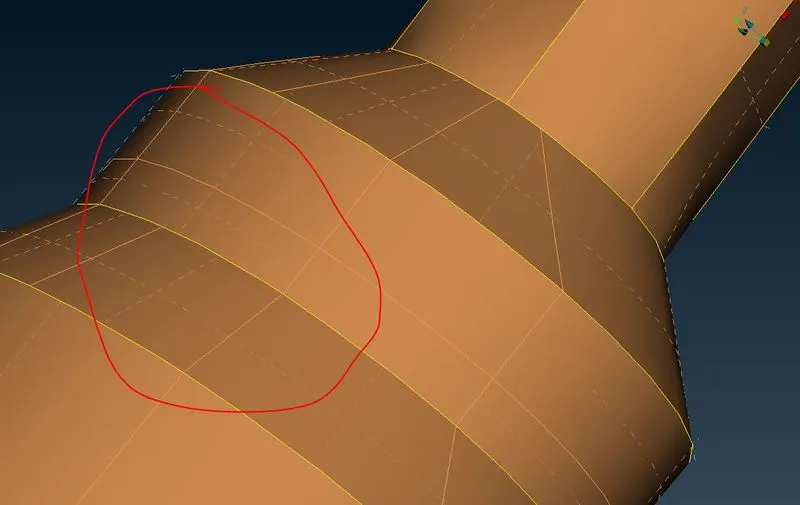
- Before mesing, we need to assign perimeter and macros length using perimeters>length in mesh module. assign value as target element length.
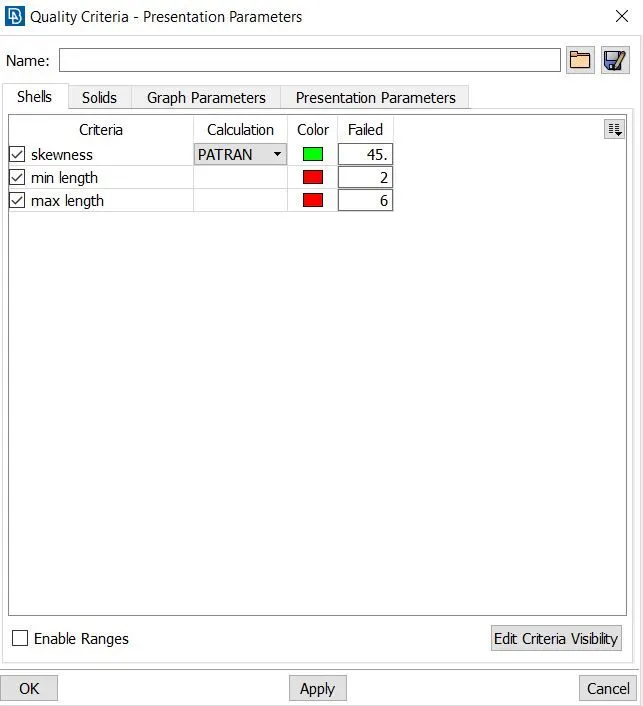
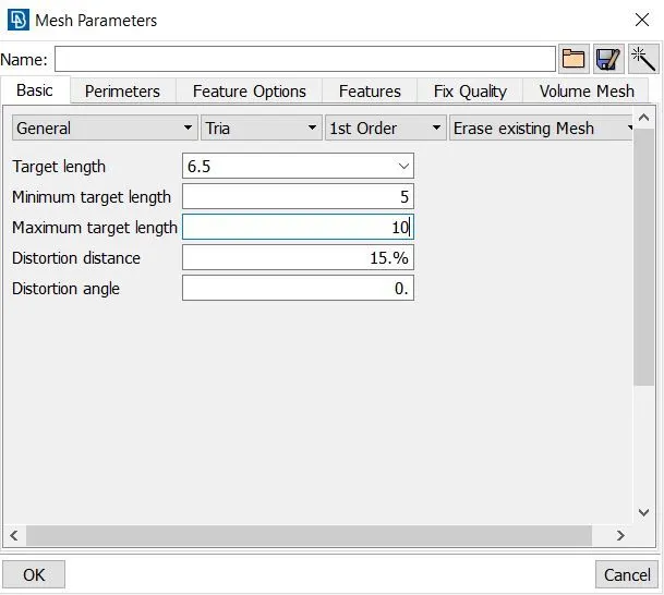
- Now Assign mesh parameters and quality as per requirements of mesh variety.
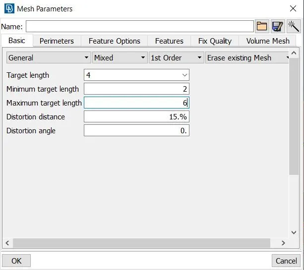
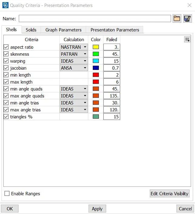
- parameters for 2D meshing lesser than 5mm thickness.
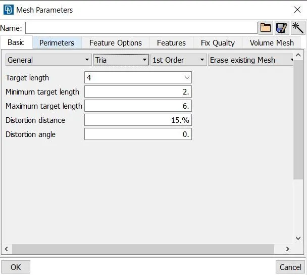
- parameters for remaining parts (using trias) excluding tyre & rim.
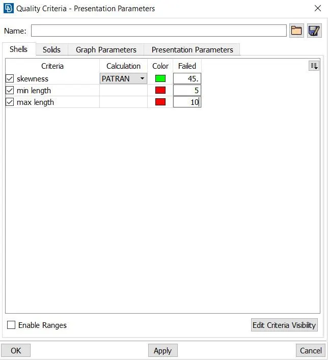
- parameters for tyre & rim 3D meshing.
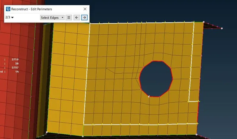
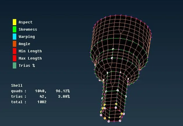
- Now start with 2D mesh using mesh generation>spot or best mesh in mesh module. I have started the mesh in less than 5mm thickness parts.If it has any elements fail just do reconstruct the mesh using shell mesh>reconstruct and use smooth tool in shell Elements>smooth to smoothening the mesh to avoid element fail.
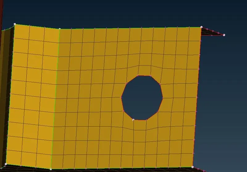
- Now start with volume mesh areas. first we have to do 2D mesh using trias in all surfaces of the part and then define the volume for the 2d mesh. so first start with rim and tyres to do meshing using trias. Mesh the surface using mesh generation>spot or best mesh in mesh module. reconstruct and smooth the mesh if it has any element fail.
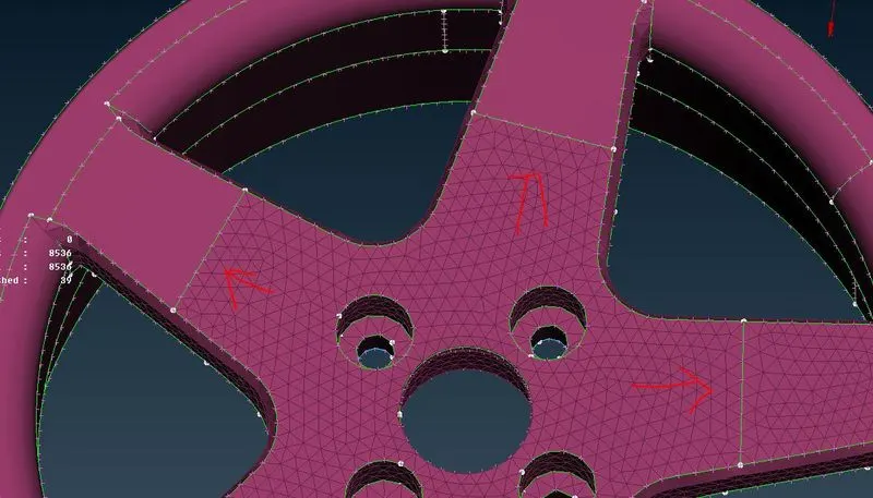
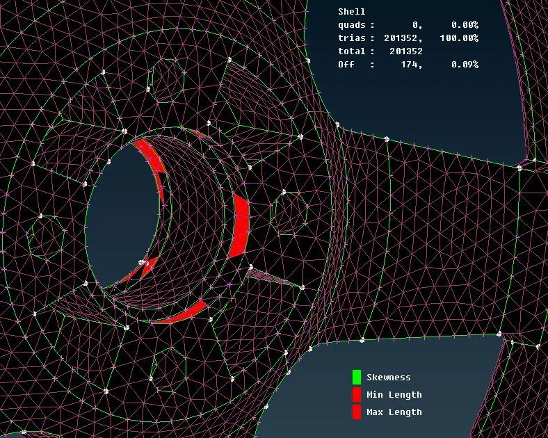
- Some areas have OFF elements (failed elements) due to some feature constraints.
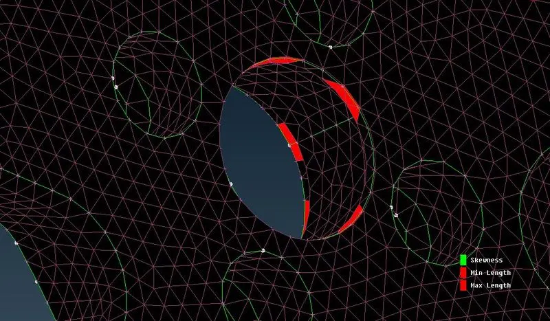
- After done all the parts now start assigning volumes for the 3D meshing parts. tihis is done by using Define>volumes>manual in volumetric mesh module. then select the region for assign volume. After assign the region now create the PID for volume mesh.
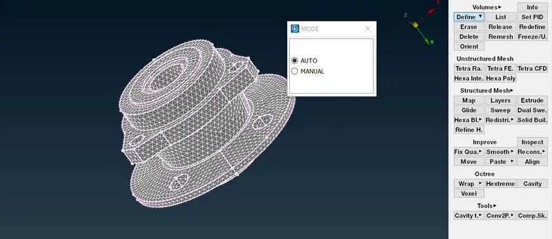
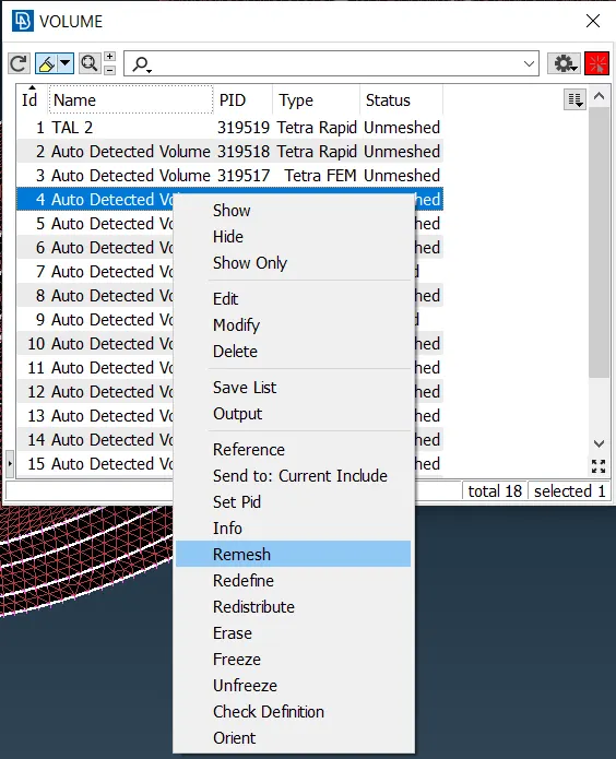
- After all list of volumes are assigned. You can accessed in voulumes>list tool in v.mesh module. The list of volumes are unmeshed. now select and right click the volume one by one and select remesh and middle click after select the remesh. now select the method or algorithms which have to do mesh the volumes by selecting tetra rapid or tetra FEM.This procedure will follow for all other volumes in the list.
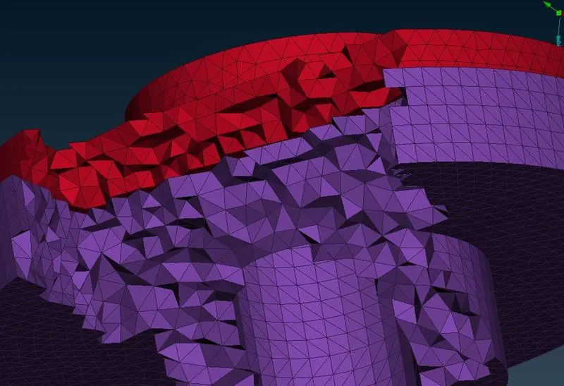
- 3D tetra elements are shown below
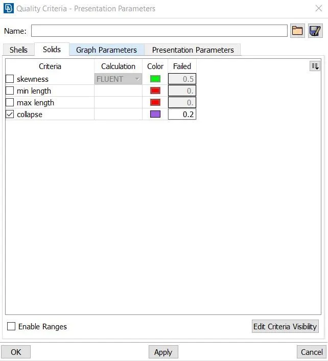
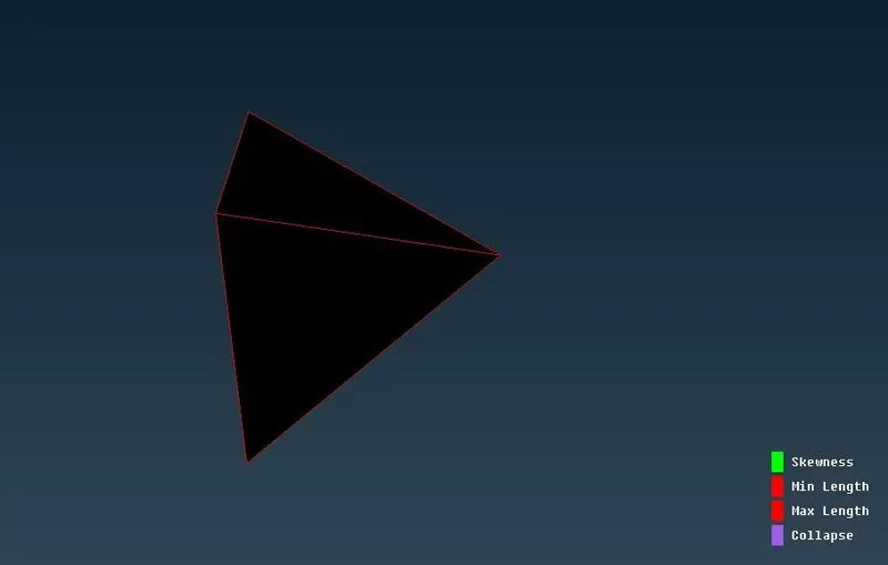
- Now check the volume mesh for tet collapse elements fail in quality criteria>solids tab. assign tet collapse as 0.2.
- If it has failed elements. we can use improve>fix quality in v.mesh module.
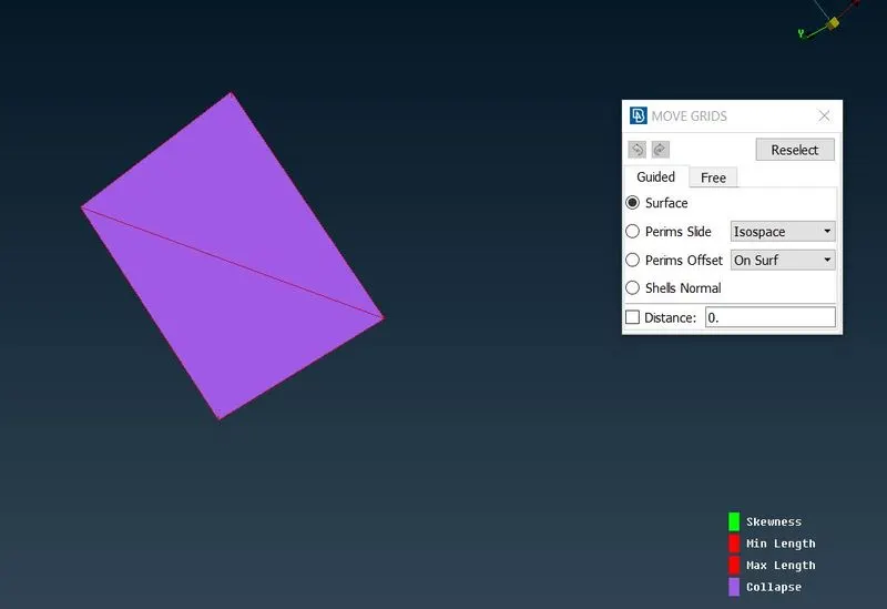
- We can use other method to remove failed elements by using grids>move free tool to move the nodes free to pass the elements as per the quality criteria.
Meshing of Spring elements:
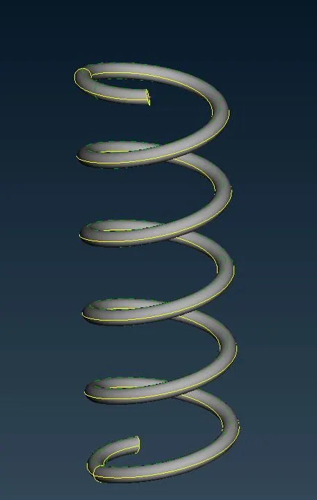
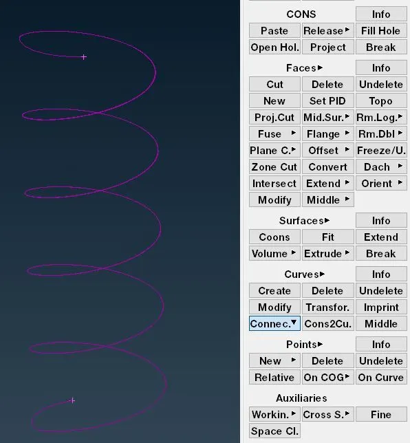
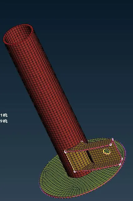
- Here we have represent spring part as 1D CBAR element. at first we should generate middle curves using curves>middle in topo module. We need select the curves in the spring part and click middle button to create mddle curve.
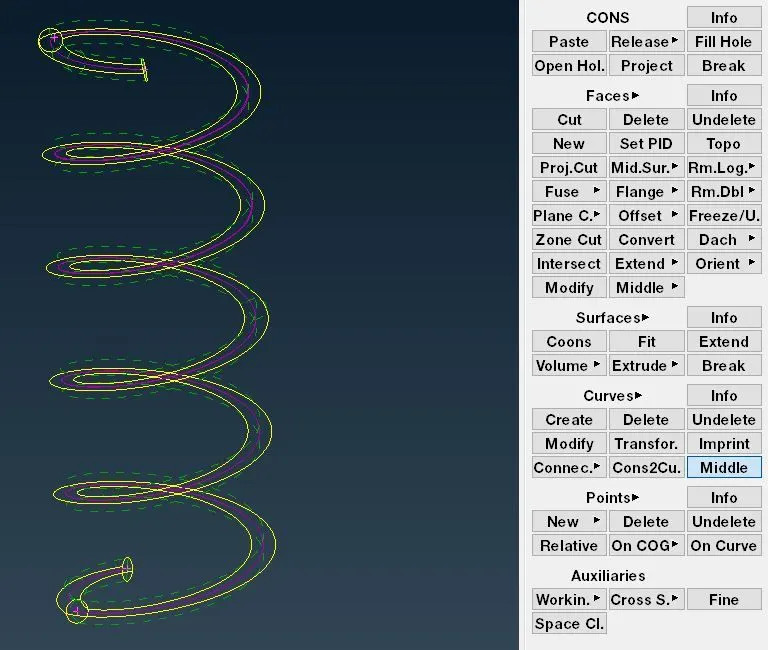
- After creating middle curve, we should connect multiple curve to single curve using curves>connect>multi in topo module.
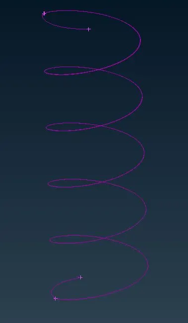
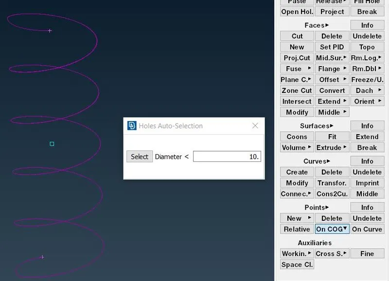
- After that we should create COG point for middle curve using points>on COG in topo module.
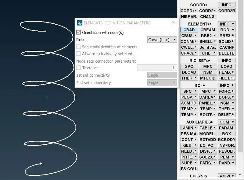
- After this we can move to Nastran deck to deploy CBAR element using Elements>CBAR and the window pops up, select orientation with nodes and curve(box) in the window.
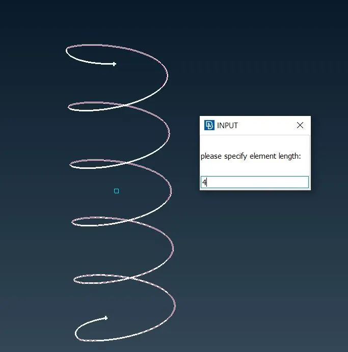
- After that, we need pick orientation point using COG point. after that we need assign element length as 4mm.
- Now clicking middle mouse button, we should assign new PID for the curve. In the next window, we should assign A-area value for the curve by clicking shift+? to assign R-Radius value for the spring. after that it can automatically calculates area value using radius.
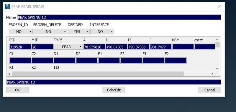
- In next window, we need assign CBAR element by giving name for that as spring.
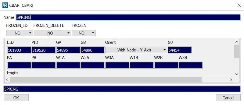
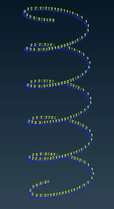
- Now the 1D CBAR elements have been created.
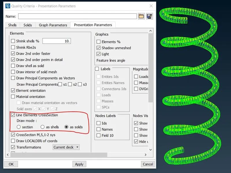
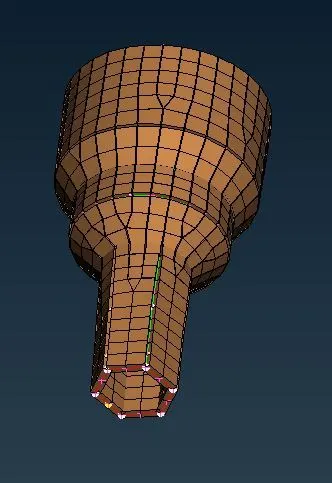
- These can be represented as 3D solids by selecting quality criteria>line elements cross section>as solids.
Connections:
- Now all the parts in assembly are meshed, we can move to connect the parts using suitable connections.
- This type of connection is very simple to do.the simple two node RBE2 connection between two different components where as shaft like cylinder structure go into the the hole.In this case, we should select two different nodes from two different components for connection. We need to select Elements>RBE2>two nodes in Nastran deck. now select two nodes from two components.
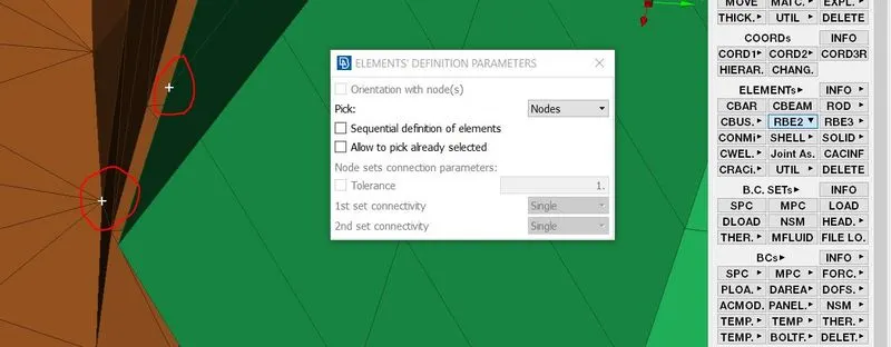
- Now we can define RBE2 element to be created.
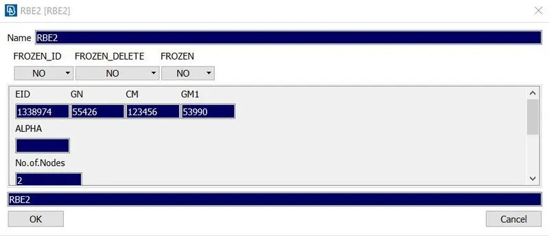
- On clicking middle mouse button, the connection would be created.
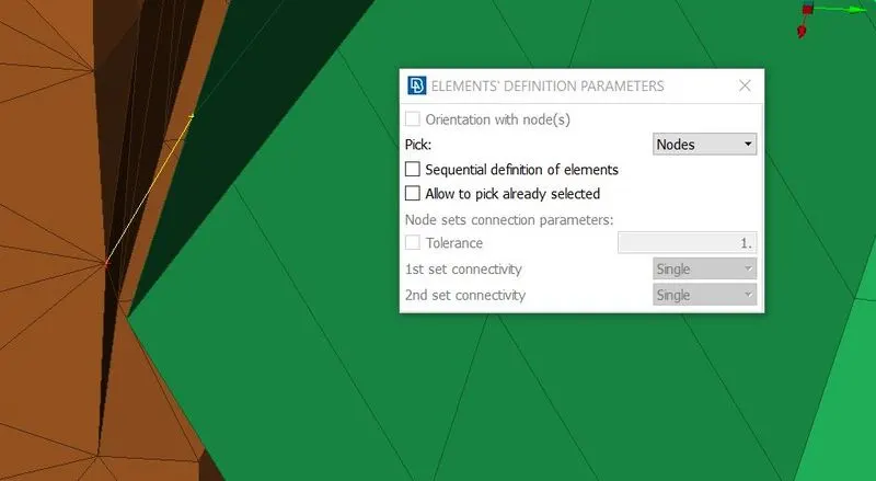
- we need to do this for more nodes to rigidious the component.
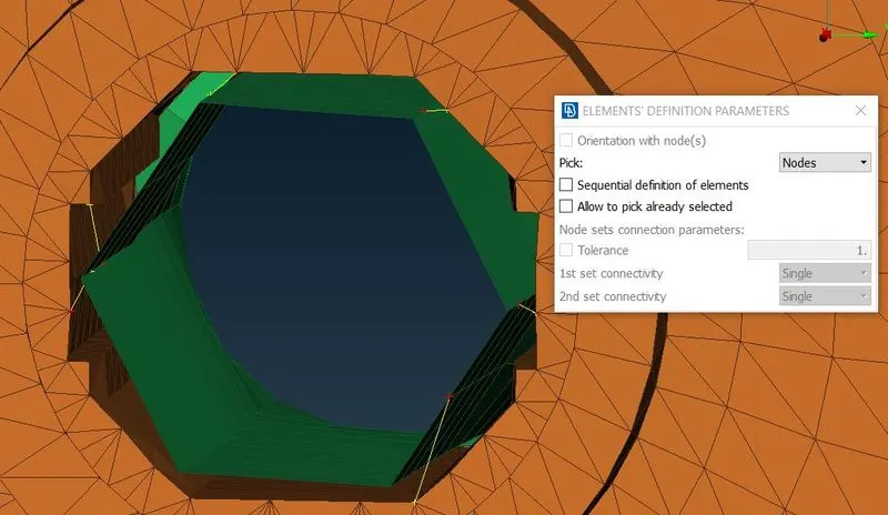
- Now we use RBE2 two nodes and many nodes tool for bolt and nut like connections.
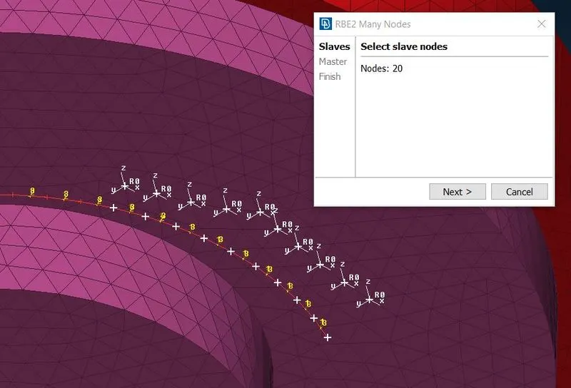
- By selecting elements>RBE2>many nodes or two nodes in Nastran deck. This procedure involves connecting two sets of RBE2 spiders using two node RBE2 element. First the RBE2 elemnt is created separately for each hole using RBE2>many nodes by selecting the nodes surrounding the hole and middle click to create RBE2 spider element.
- Now we can move to next parallel component. Select the nodes surrounding the hole by using same procedure.
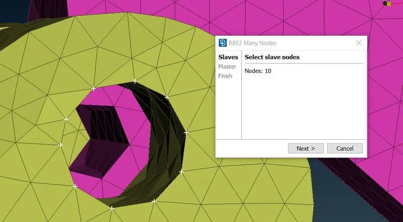
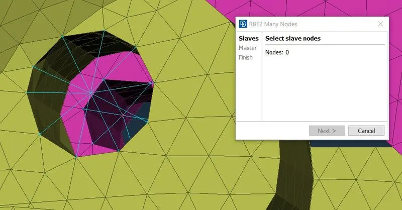
- Now we have two master nodes which are to be connected. To connect the nodes by using Elements>RBE2>two nodes. Select the nodes and click middle button to deploy the connection using two master nodes.
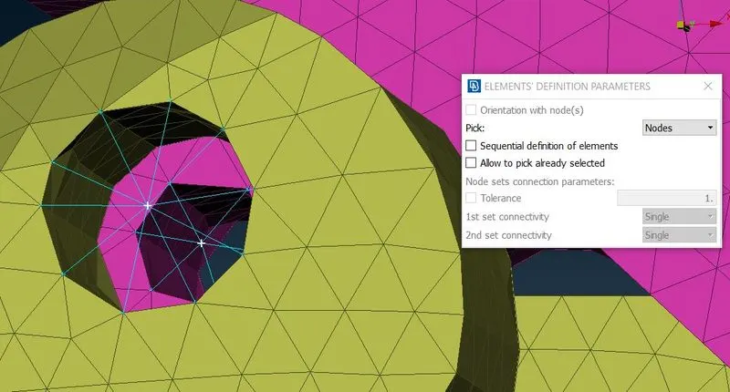
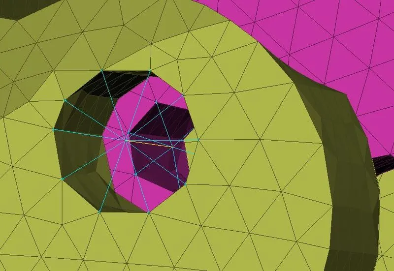
- This procedure is used for all the bolt and nut connections.
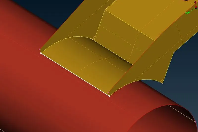
- Here we can go for seam weld connection. In case of creating seam weld, we should create curves where as the seam weld would take place by using Currves>con2curve in topo deck. this will let us select the edge to convert the curves.
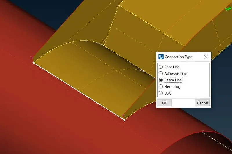
- Now convert the curve to seam line by using convert>seam line.
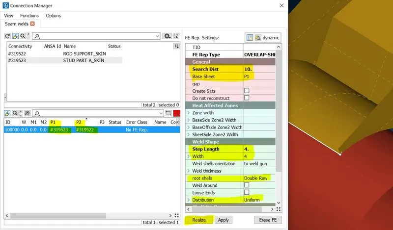
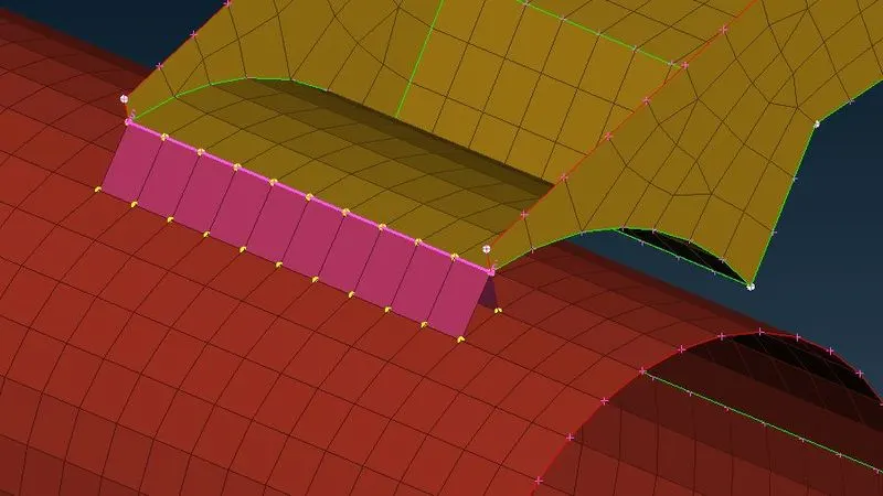
- Now we should select the connection manager to deploy seam weld connection. select connection manager after that select the seam line. now the connection manager window pops up. here we have to select P1 and P2 for connection. Right click the P1 and P2 and press F1 for select the particular PID for connection. we should taken care for selecting the right component for base sheet. here we have parallel connection so we should choose overlap shell as FE type. Assign step length as and width as 4 and search distance as 10. root shells as double row. now select realise to deploy the connection.
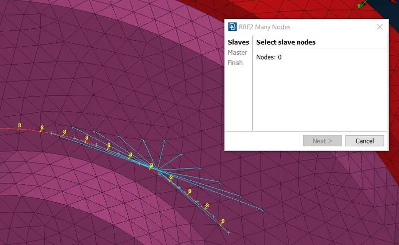
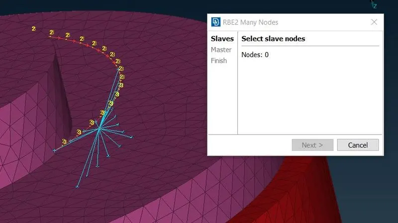
- Now we need to deploy connection for spring element with neighbouring parts. Here we can use cluster RBE2 elements. this process is a straight forward process. we should use RBE2 element for connection by using Elements>RBE2>many nodes in Nastran deck. In this case, we deploy many nodes tool to connect spring and neighbouring part via single master node. This is to be done by selecting two set of nodes, one from spring and other from neighbouring part by single stretch and click middle button to deploy cluster RBE2 element. Here we had connect both spring and neighbouring part by single master node. this is known as cluster RBE2 element.
Reflection:
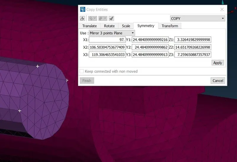
- Now We have meshed the whole assembly and deployed the suitable connections. now we need to transform a copy by symmetric side of the assembly by selecting transform>copy.
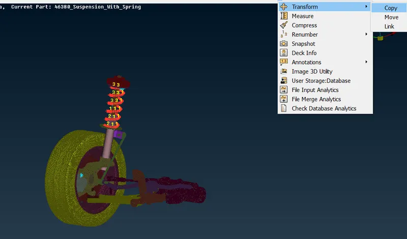
- Here we need to select the whole assembly and click middle button to go for next step.
- Here we have to select reference point to transform a copy by selecting three different points in single area to connect the symmetric part symmetrically.
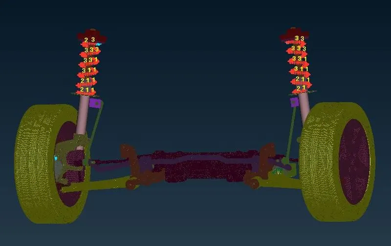
- Now click middle button to finish the action.Here we have the reflected symmetric side of the assembly.
Final model images:
Mesh for midsurfaced parts (2D shell elements).
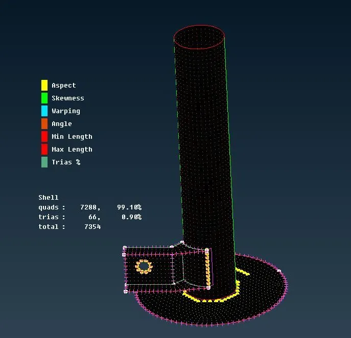
Representation of solid elements.
Mesh for tyre & rim.
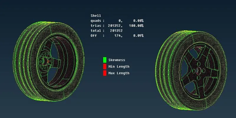
Some areas have OFF elements due to feature constraints.
 .
.
Mesh of remaining parts using trias.
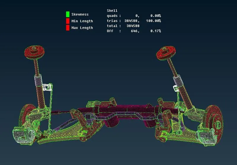
Some areas have OFF elements due to feature constraints.
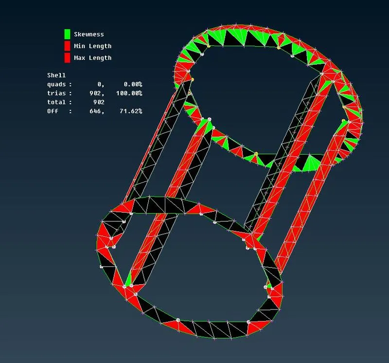
3D mesh representation.
Full model with no tet collapse.
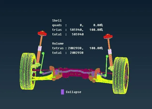
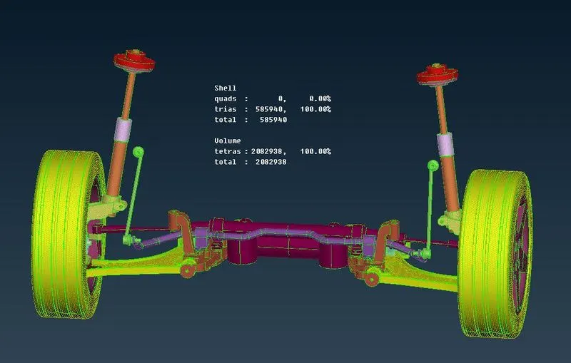
A entire model including symmetric side and connections.
Learning outcomes:
- Learnt more deeply to mesh the model using tetra elements and deploy the connections for suitable areas.
- Learnt to work on different parts on this assembly.
- Learnt to create 1D element to represent the spring.
Conclusion:
The given suspension assembly had meshed on both 2D and 3D elements as per the given quality criteria and deployed the suitable connections through the assembly.A symmetrical side of assmebly were created by transform tool.