Creation of 1D elements on the following components with given cross section and degree of freedom(DOF) using hypermesh.
Creation of 1D elements on the following components with given cross section and degree of freedom(DOF).
Objective: To create the 1D elements such as ROD, BEAM, BAR and apply mass and spring elements for the given component using given dimensions and DOF.
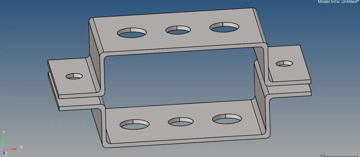
img.1 imported model
Procedure:
- first import the geometry from the given iges model.
- check the geometry and create the midsurface for the given geometry separately using midsurface command in geometry tool.
- select the top bracket surfaces for extraction. select extract and then rename the mid surface 1 as bracket 1 and create the new component in tab bar and rename it bracket 2 because we want to create a midsurface separately for two brackets.follow the same procedure to create midsurface for bracket 2.
- now move the created mid surface to the bracket 2 component using organise command in tool option.
- now the midsurfaces of bracket 1 & 2 are created and change the color as your preference.
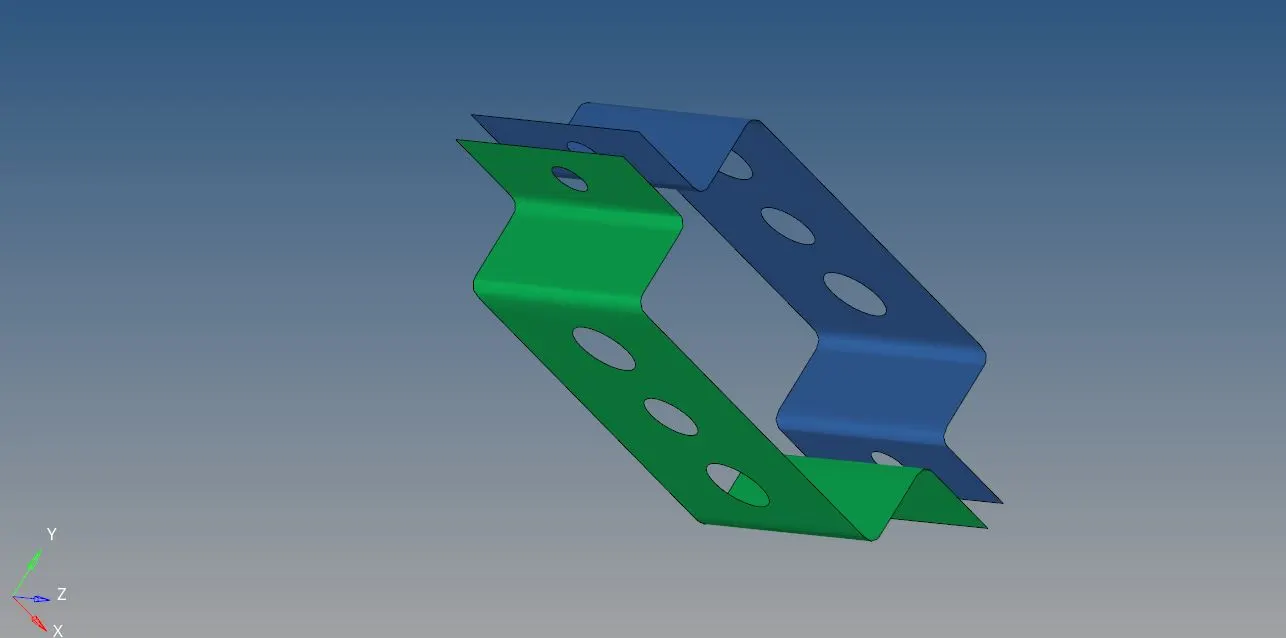
img.2 midsurface of bracket 1&2
now delete the wireframe geometry using delete command and click delete entity.
then hide the solid part of bracket 1& 2 for future use.if you delete the solid part we cannot reuse it when it is needed.
now for 3D representation,create material and property for braket 1 & 2 and give the thickness for brackets using propery option. for this click right in tab bar now create-material and then create-property for bracket 1&2.
material- steel
| property | card id | material | thickness |
| 1 |
PSHELL |
steel | 2mm |
| 2 | PSHELL | steel | 2.5mm |
now assign the properties for respective brackets.assign property 1 for bracket 1 and property 2 for bracket 2.
next step create a 2D mesh for both brackets before that create washer spilt for the holes in the surfaces offest of 4mm using washer split command in quick edit tool.
go to 2D,select automesh and select element size as 8 and element type as mixed and click mesh after this clean up the mesh by increasing or decreasing the nodes.
2D mesh was created for using elements to create nodes for 1D elements.
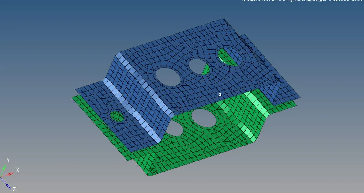
img.3 2D mesh of the bracket 1&2
now create a 1D elements for the midsurface of the brackets.first create rbe2 link for a, d&e first create rbe2 for a using only translational DOF, select rigid command in 1D tool and create the nodes for rbe2 link,uncheck the translational DOF and then click create now rbe2 link is created.and follow the same procedure for d&e by using with all DOF.
now create rbe3 link for b&c. select rbe3 command in 1D,create nodes for create link and check all DOF for b and uncheck x and y DOF for c and select create.
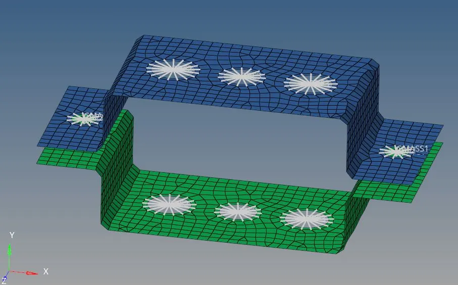
img.4 rbe2 & rbe3 link created with DOF
create 1D element using rod & bar command in 1D tool.select the nodes and keep the element type as CROD, CBEAM, CBAR and click create.
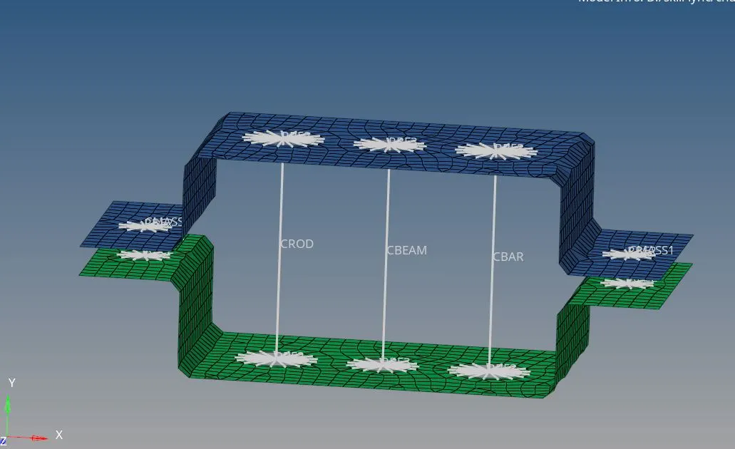
img.5 creation of 1D elements of ROD, BEAM, BAR
next create cross sections for rod, beam,bar.select hyper beam command in 1D tool. select standard section and select hyperbeam now click create.the hyper beam panel will appear.
Box cross section dimension for ROD
| Dimension |
| a- 12 mm |
| b- 10 mm |
| t- 0.75 mm |
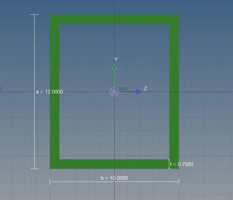
img.6 box cross section for rod
I section dimension for BEAM
| dimension |
| a-8mm |
| b-10mm |
| c-8.5mm |
| t1-0.75mm |
| t2-0.6mm |
| t3-0.6mm |
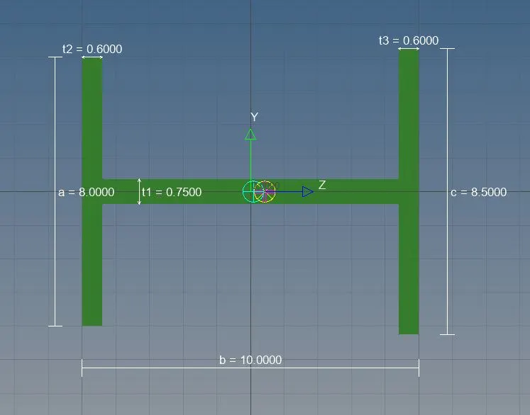
img.7 I section created for beam
Cross section dimension for BAR
| dimension |
| DIM1- 5MM |
| DIM2- 1.2 mm |
| DIM3- 10 mm |
| DIM4- 1.2mm |
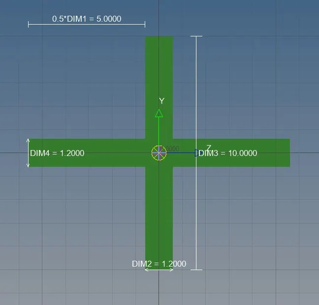
img.8 cross section for bar
after that create ROD(a) using rbe2 link and BEAM(b) & BAR(c) using rbe3 link without assign the cross section.
now create the property for rod,beam&bar.
| property | card id | material | beam section |
| ROD | PROD | steel | rod |
| BEAM | PBEAM | steel | beam |
| BAR | PBAR | steel | bar |
update the property for their elements respectively.select rod-update-property(rod) and click update. for beam&bar click bar-update-property(bar)&property(beam) and click update.now the properties are assigned properly for the components with respective cross sections.now u can see the cross section visually by usind 1D detailed element representation command.
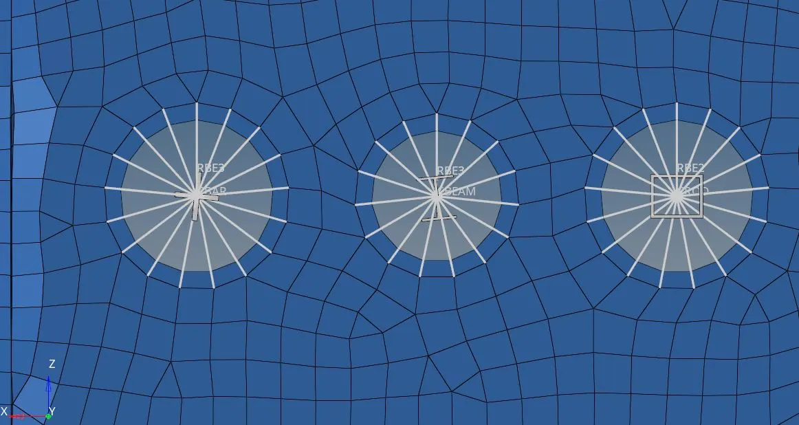
img.9.1 cross section of rod, beam,bar
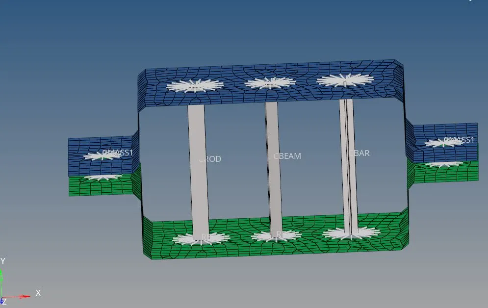
img.9.2 cross section of rod,beam,bar
now create the masses for d&e using rbe2 link with magnitude of 10 by selecting MASSES command in 1D tool.select the particular nodes in d&e and select element type as CMASS1. and click create.
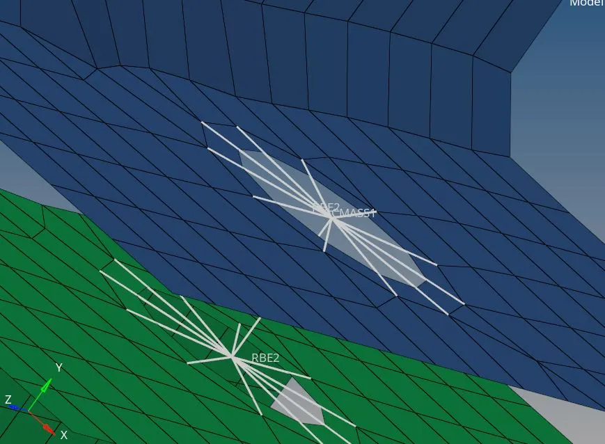
img.10 Applied mass of magnitude 10 in d&e
now connect the brackets by spring element in d&f and e&f using command spring in 1D tool. now select nodes and element type as CELAS1 and select create.
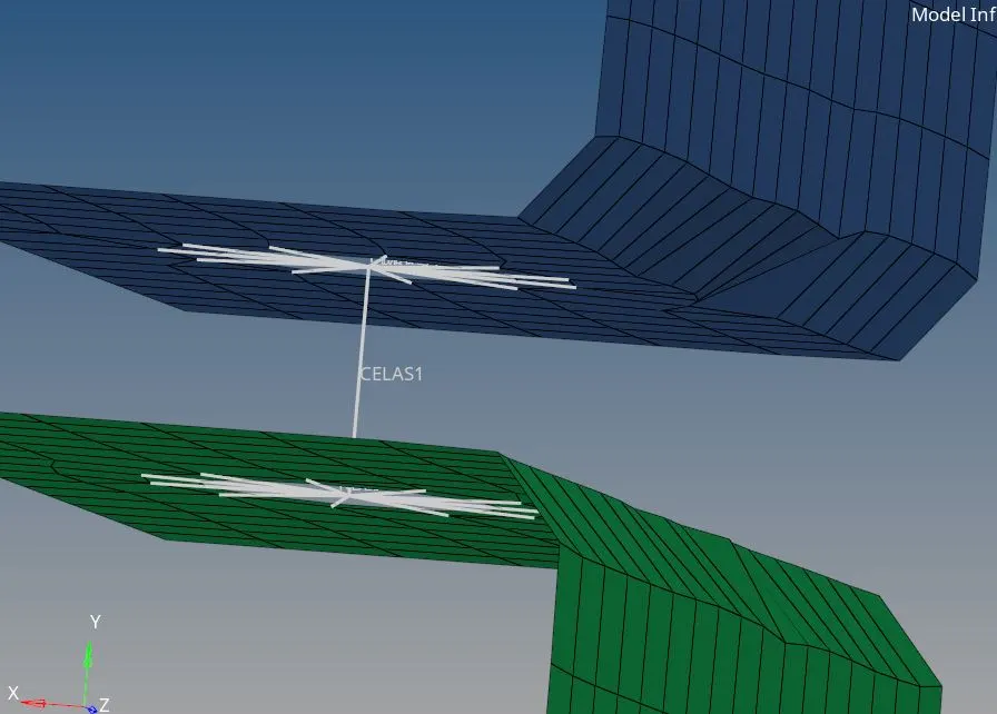
img.11 applied spring elements in d,e&f
now change the midsurface 2D into 3D presentation of the component byseeing thickened surface by visually selecting 2D detailed element representation.
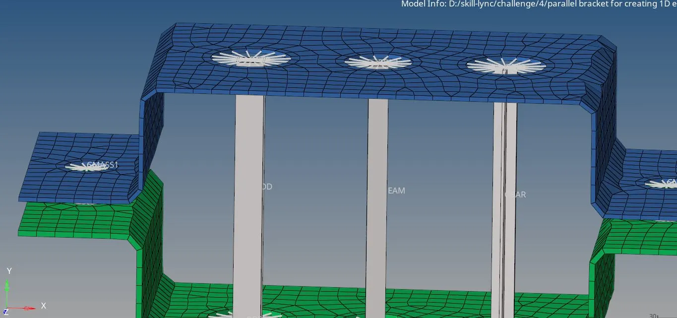
img.12.1 3D representation of the midsurface of the bracket.
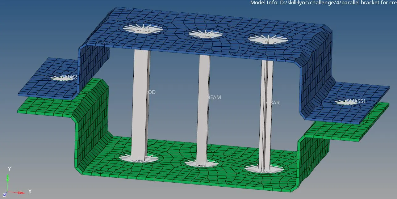
img.12.2 final model of created 1D element on the given cross section and DOF
conclusion:
- Based on this challenge, we learnt how to create a 1D elements using cross section and DOF.
- how to create a mid surfaces for the model given.
- how to assign material and property for 1D elements.
- how to create a cross sections using given dimensions by hyperbeam option.
- how to create elements like rod, bar,beam,spring and how to give mass for the elements.