Modelling Spotwelds
Objective:
To Create Spot welds using beam and solid elements and set up solver inputs for the simulation and assign output requests.
Procedure:
Case:1- Checking the failure of the spot weld using beam element:
Creating spot welds using beam element:
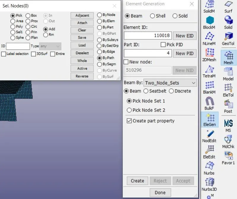
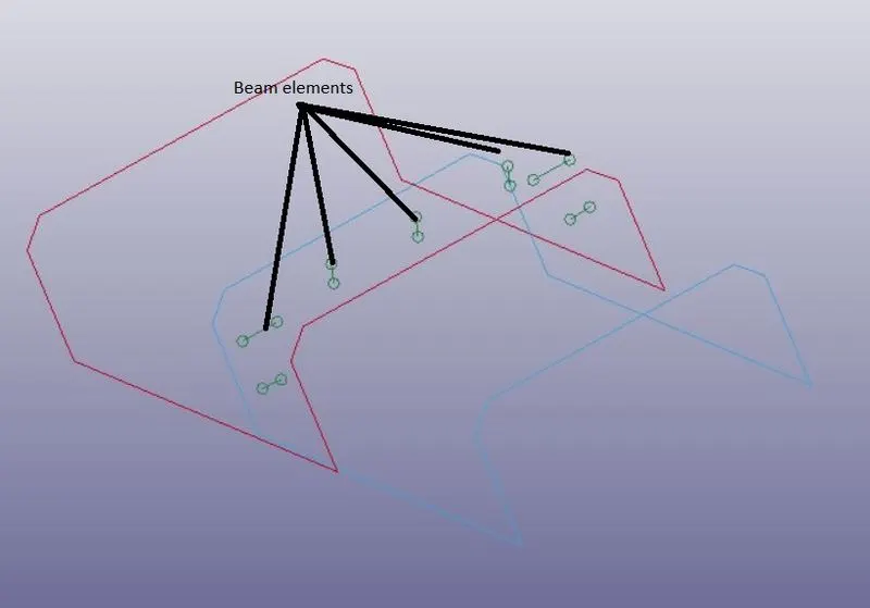
Here we can create beam elements for spot welds using Mesh>element generation. Now select the beam tab. Select beam by as two nodes. Now select node 1 using pick node set 1 and select node 2 using pick node 2. Click create to done. Use the same procedure for creating many other beam elements.
Setting Solver deck inputs:
Creating material card for shell and beam elements:
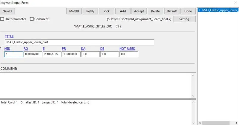
To create material cards for the shell elements. By clicking Model & part>keywords>all>MAT>Mat-1 elastic >assign values of (material id, RO, Young’s modulus, Poisson’s ratio)>accept>done. Here we assigned steel material values for the material card.
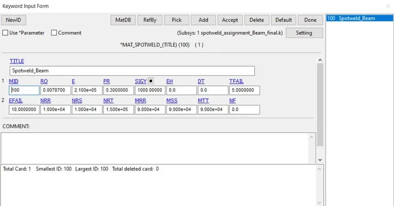
For beam elements, Delete the existing MAT id which is automatically created. For new MAT id, By clicking Model & part>keywords>all>MAT>MAT 100(spotweld) >assign values of (material id, RO, Young’s modulus, Poisson’s ratio, SigY, Tfail, Efail)>accept>done. Assign other parameters such as NRR, NRS, NRT, MRR, MSS, MTT.
Creating Section card:
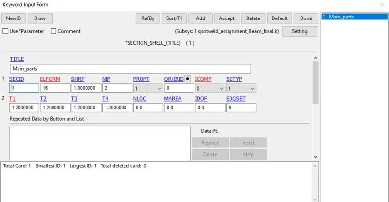
we need to define a Section id for the shell elements. By clicking Model & part>keywords>all>section>shell. Now assign values and click accept and done. Assign thickness as 1.2mm and Assign element formulation ELform as 16 for fully integrated elements with faster speed.
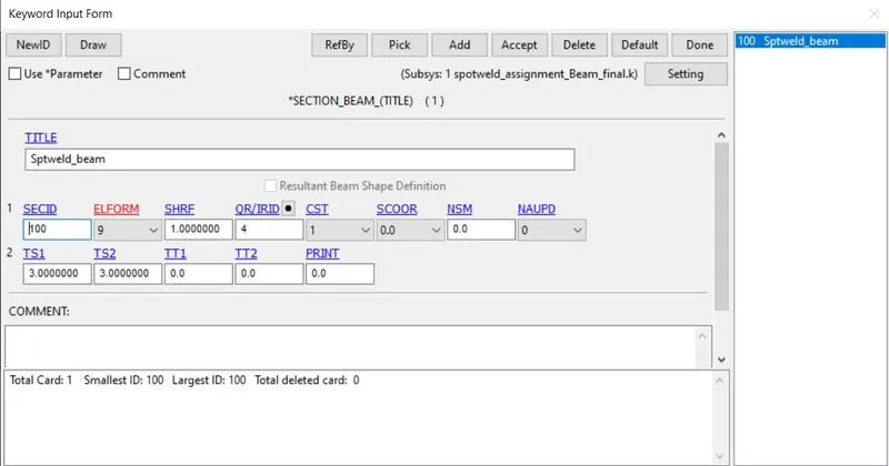
we should define a Section id for beam elements. By clicking Model & part>keywords>all>section>beam. Now assign values and click accept and done. Assign cross-section as 3mm and Assign element formulation ELform as 9 specially represented for spot-weld beam elements.
Assigning Material id and Section id for part:
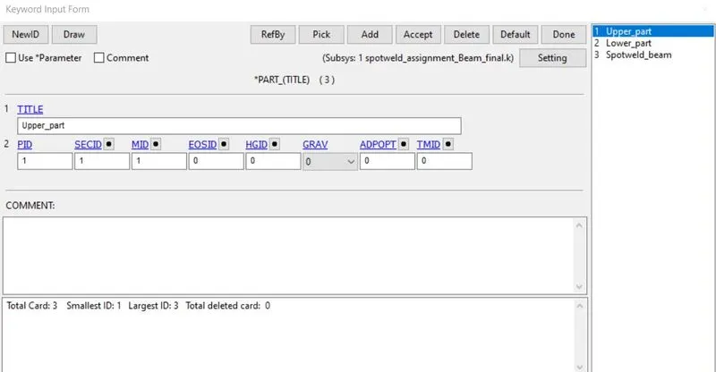
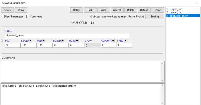
Now go to Model & part>keywords>part. Now select shell part and assign material and sec id. Do the same for the spot-weld part.
Creating rigid wall:
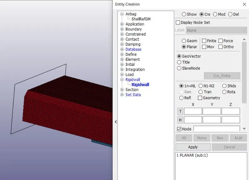
To check the spot-weld failure, we need to crash the model using the rigid wall. So we need to create a rigid wall using Model & part>Create entity> Rigid wall. Now select planar and select 1n+nl. After that Click one node at one end and assign -10mm at x-axis from that node. now apply and done.
Defining initial velocity for the Model:
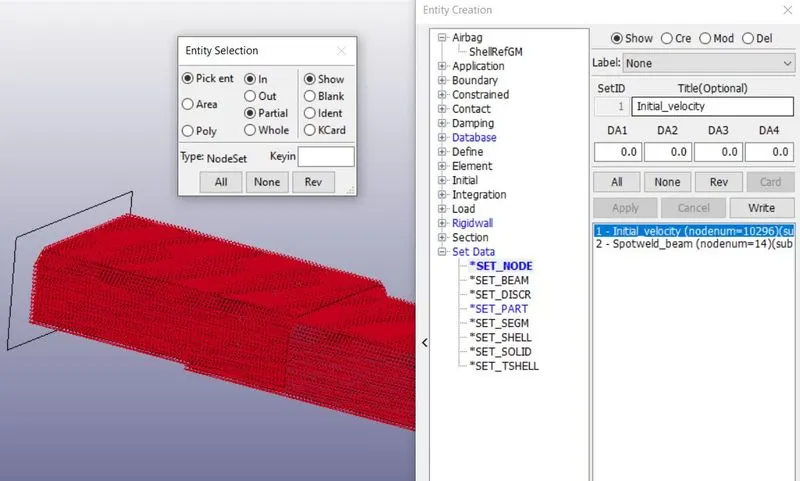
At first, we need to create a node-set for assigning initial velocity. For Node set id creation, go to Model & part>Create entity>Set data>set node>create>pick by part>assign a title and set id>apply>done. We need to assign a set id and title and then pick the nodes using the part tool. After that click apply and done.
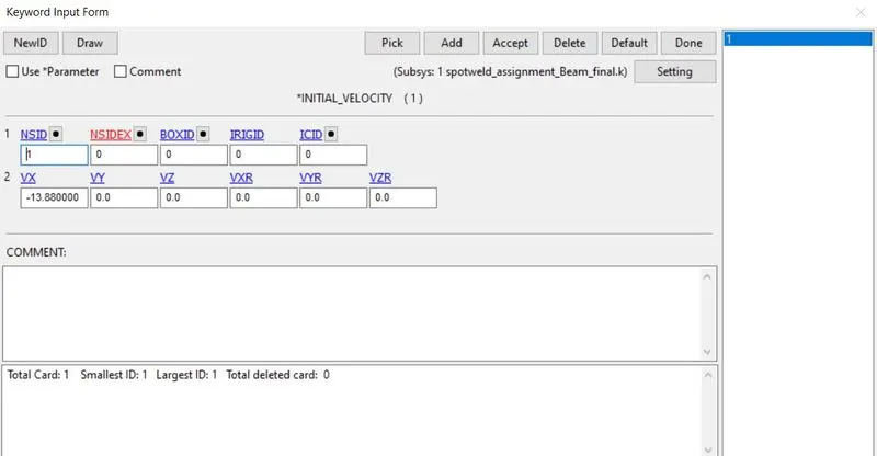
Now go to Model & part>keywords>initial>velocity. Assign value as -13.88mm/ms (50kmph) through x-axis and assign node-set id value. Now accept and done.
Defining contact card:
Now we need to create two contact cards for self contact and spot weld. At first, we need to create a node-set for assigning the control card.
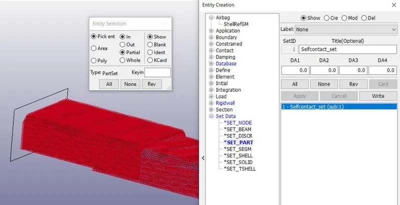
For part set id creation, go to Model & part>Create entity>Set data>set part>create>pick by part(top and bottom part)>assign a title and set id>apply>done.
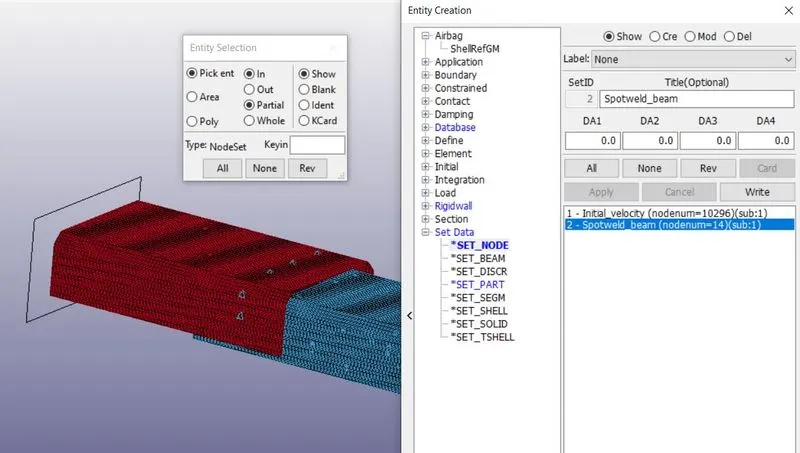
For spot-weld, we need to create a node-set id. For node set id creation, go to Model & part>Create entity>Set data>set node>create>pick by node(beam element nodes)>assign a title and set id>apply>done. Select the spot-weld beam element node.
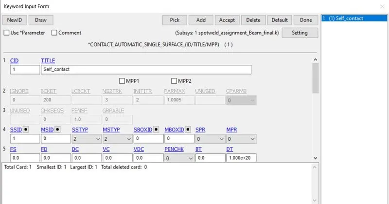
Here we need to assign self contact for the model. So we can give only slave set id to assign self contact by clicking Model & part>keywords>Contact>Automatic_single_surface. Assign the slave set id type as 2 for part set id and put SSID value. Click accept and done.
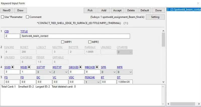
For spot-weld contact, we should assign both slave and master segment id by clicking Model & part>keywords>Contact>Tied_shell_edge_to_surface. Assign the slave set & master set id type as 2 for part set id and select spot weld as a slave and assign shell part as master using part set id. Click accept and done.
Defining Cross-section for the model:
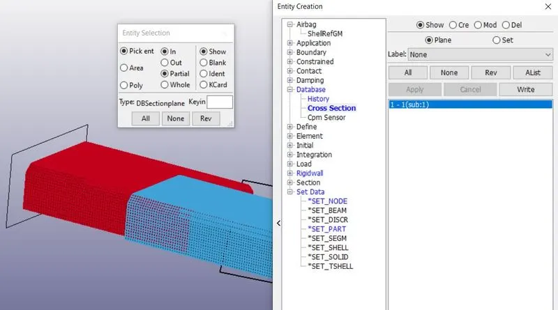
Now go to Model & part>Create entity>database>cross-section. Now select create>plane>3nds. Now click three nodes to assign a plane parallel to the rigid wall. Click apply and done. Now the cross-section was created.
Defining History node for particular node:
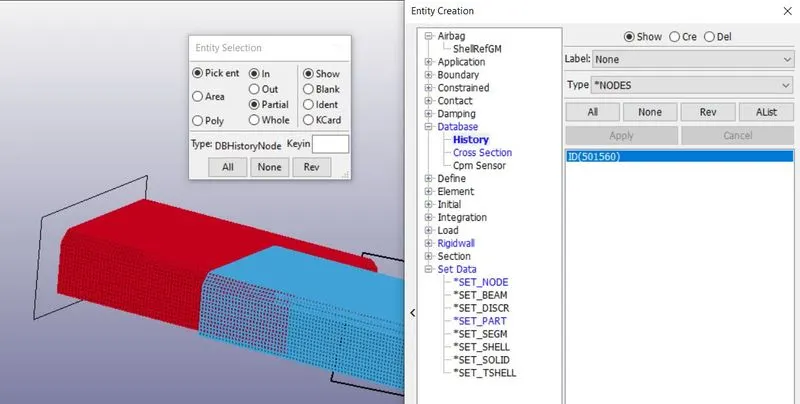
Now go to Model & part>Create entity>database>History >create>node. Now pick the node and select apply and done. Now a node was assigned.
Defining output requests:
Now we need to give output requests for the graphs we want to plot. By clicking Model & part>keywords>Database>ASCII. Here we need to assign DT for GLSTAT, MATSUM, RCFORC, NODOUT, SECFORC, SWFORC. Assign DT value as 0.1ms.
Defining animation output file:
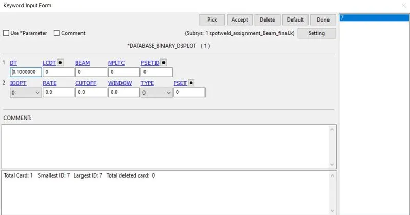
we need to give output requests for the animation. By selecting Model & part>keywords>Database>Binary D3plot. Here assign DT value as 0.1ms.
Creating control termination card:
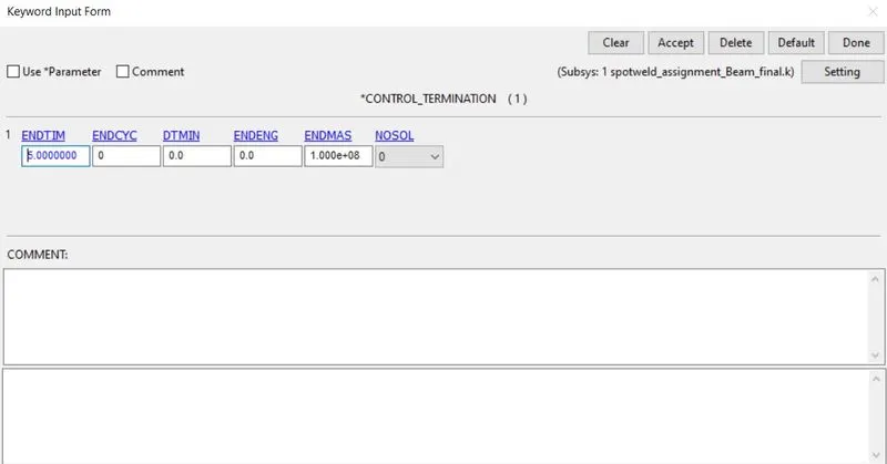
We need to put end time for the simulation for that select Model & part>keywords>Control>termination. Now assign end time as 5ms.
Case:2- Checking the failure of the spot weld using solid element:
Here we need to change some of the keyword cards were shown below,
Creating spot welds using Solid elements:
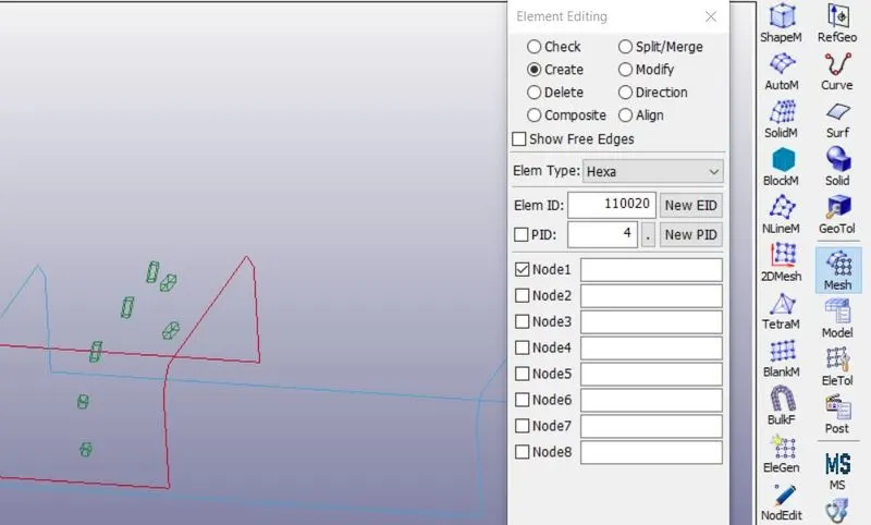
Here we can create beam elements for spot welds using Mesh>element edit. Now select the create tab. Select element type as solid. Now select nodes 1 to 8 for creating a solid element. Click create to done. Use the same procedure for creating many other solid elements.
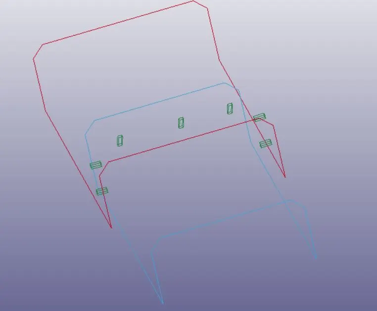
Creating material card for shell and beam elements:
For solid elements, Delete the existing MAT id which is automatically created. For new MAT id, By clicking Model & part>keywords>all>MAT>MAT 100(spotweld) >assign values of (material id, RO, Young’s modulus, Poisson’s ratio, SigY, Tfail, Efail)>accept>done. Assign other parameters such as NRR, NRS, NRT, MRR, MSS, MTT.
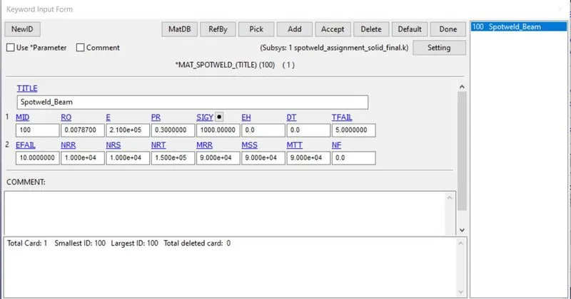
For shell elements, follow the same procedure used in case-2.
Creating Section card:
we should define a Section id for solid elements. By clicking Model & part>keywords>all>section>solid. Now assign values and click accept and done. Assign sec id and Assign element formulation ELform as 1.
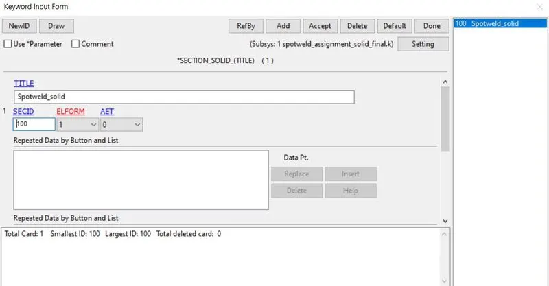
Defining contact card:
At first, we need to create a part-set for defining the control card.
For part set id creation, go to Model & part>Create entity>Set data>set part>create>pick by part(solid elements spot weld)>assign a title and set id>apply>done.
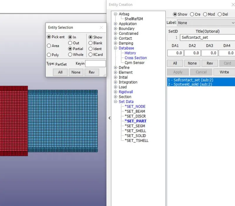
For spot-weld contact, we should assign both slave and master segment id by clicking Model & part>keywords>Contact>Spotweld. Assign the slave set & master set id type as 2 for part set id and select spot weld as a slave and assign shell part as master using part set id. Click accept and done.
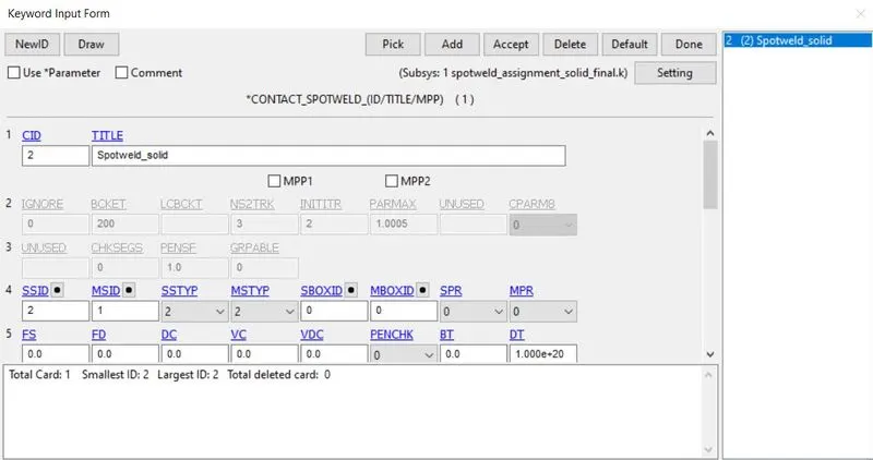
Othe solver inputs are same for the case-2 also.
Post-processing results:
Comparison of von mises stress:
Case-1:
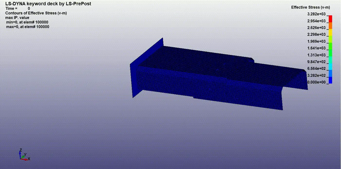
The maximum stress was induced in the model is 3.282pa. Due to the instability of the spot weld(beam element), we got maximum stress at the spot weld area when the model got impacted.
Case-2:
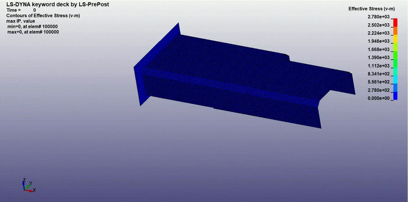
here this animation shows that the maximum stress is induced in the model is 2.78pa. it is lower than case-1 because of the stability of the solid elements used for spot-welds.
Comparing the energy graphs for both cases:
Case-1:
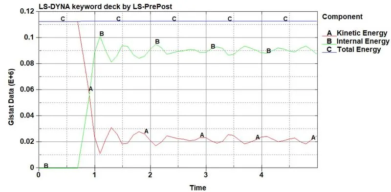
Here the kinetic energy drops down at 1.2ms. at that otime, the internal energy maximize at 0.1J. Due to the absorbtion of knietic energy, the part get more internal energy at 1.2ms after that the energy goes constant at the end time.
Case-2:
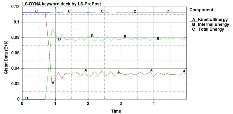
In case 2, the kinetic energy drops down even before at 0.8ms. at the same time, the internal goes higher at 0.09J. when we compared both case 2 energy absorption is lesser than case 1 due to the solid element spot-weld.
Acceleration of nodes on both cases:
Case-1:
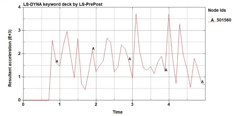
Here the acceleration occurs maximum at 3.1ms at 3.7mm/ms^2. the node acceleration is high compared to case 2 due to instability in beam elements.
Case-2:
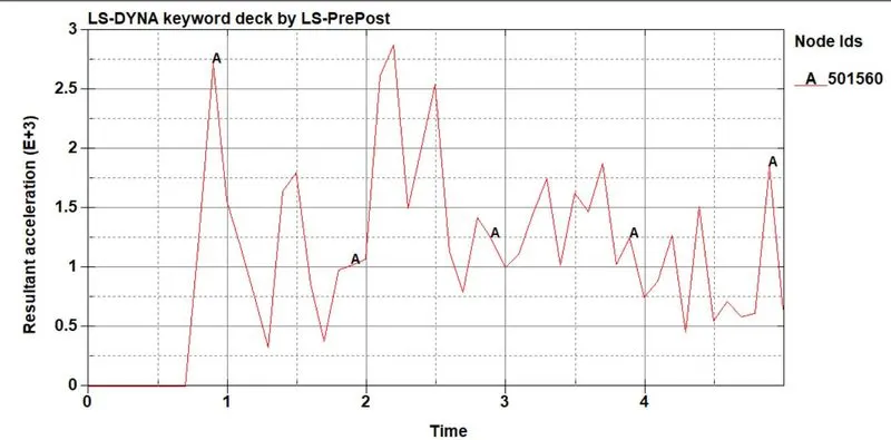
the acceleration reaches the maximum of 2.2ms at 2.8mm/ms^2. the node acceleration is lower than case 1. The solid elements are higher stable than beam elements.
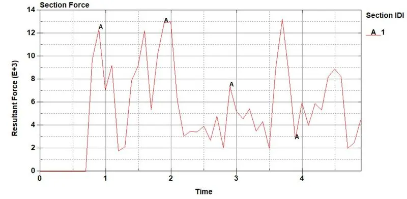
Comparing section force on both cases:
Case-1:
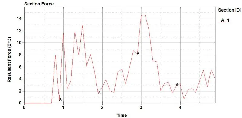
The cross-section force reaches a maximum of 3.3ms at 15N. It is higher than case 2. the force of the section was higher due to the impact force created during the impact on the wall.
Case-2:
The resultant force reaches a maximum of 12N at 2ms. The impact force acts earlier on the cross-section compared to case 1.
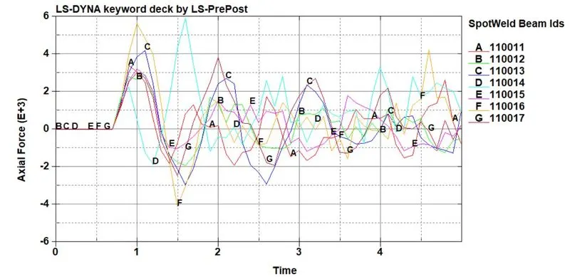
Comparing axial forces at spot welds on both cases:
Case-1:
In this case, the axial force is a maximum of 6N at 1.6ms on node 110014. Axial force is higher compared than case 2.
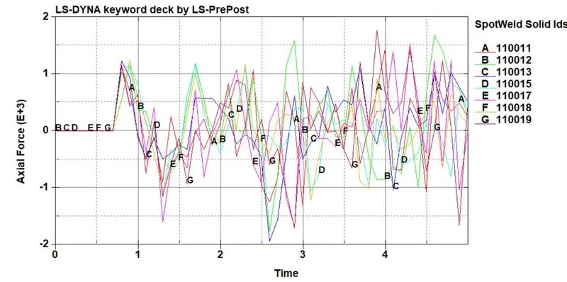
Case-2:
in this case, the axial force reaches maximum of 1.8N at 3.78ms on node 110019. Due to the solid spot-weld element, the part has more stability than case 1. So that the force is lesser than case 1.
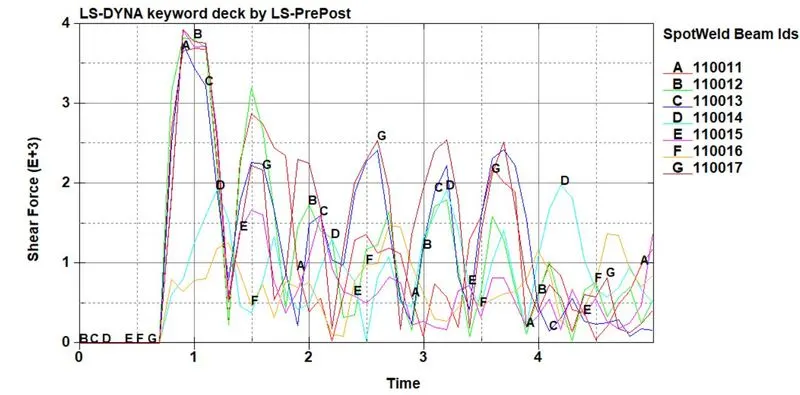
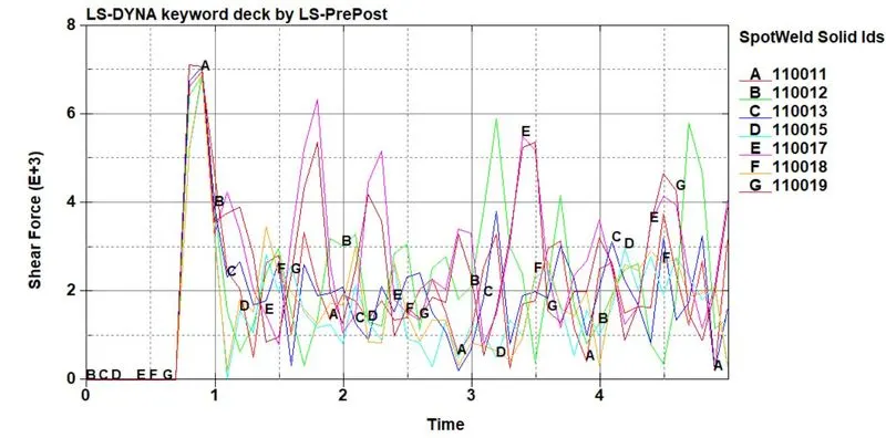
Comparing shear force on both cases:
Case-1:
The shear force reaches maximum of 3.9N at 0.8ms on node 110011. The force reaches maximum during the impact. It is lesser than case 2.
Case-2:
the shear force reaches maximum of 7N at 0.8ms on node 110011. the shear force reaches maximum during the impact due to the stable solid element, the shear force is maximum at the spot weld areas. It is higher than case 1 resultant force.
Conclusion:
The given model was analyzed using different spot-weld elements(solid, beam) and set up the solver inputs and defined output requests for the history file. After that the animation file was created. Finally the results were compared for both case 1 and case 2 above.