Drop test Challenge
Objective:
To set up solver input and output requests for the drop test of a smartphone.
Procedure:
1. Here we have .K keyword file with only mesh with basic node, element, part keywords only. So we need Set up the solver keywords for the model and give end time for the solver and Give output requests for the graph and animation files.
2. At first, import the keyword file using File>open>Ls_dyna keyword file in LS-Prepost.
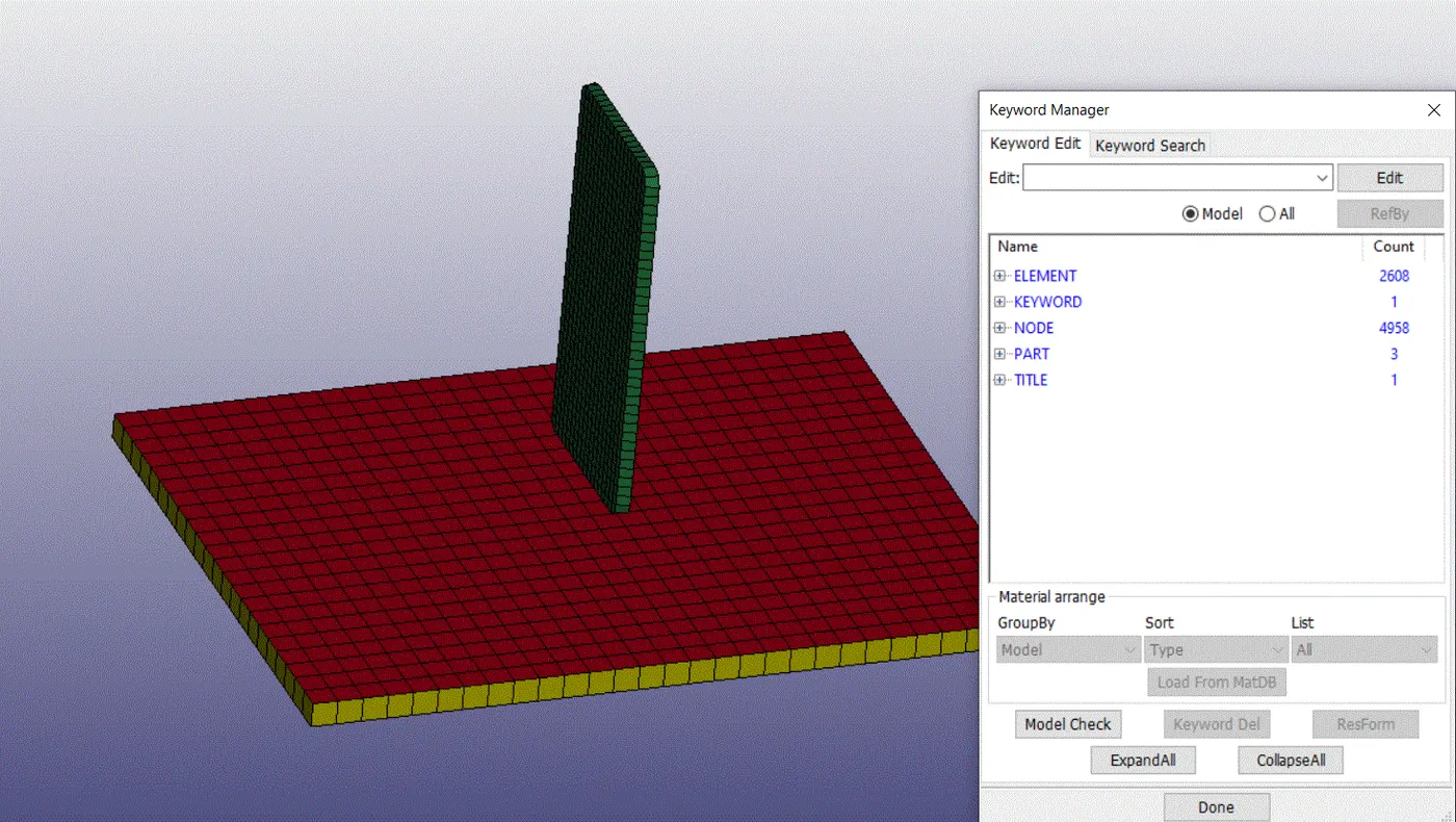
3. Now we need to delete the solid mesh in the ground part because we have both shell and solid mesh. So delete the solid mesh using Model & part>keywords>part>select the solid mesh>delete>done.
4. Here in LS-Dyna, there is no unit system to assign automatically. So we should choose the unit system as our wish. Here we have an electronic device in this industry they are following grams, millimeters, milliseconds as their unit system. So we should follow that unit system.
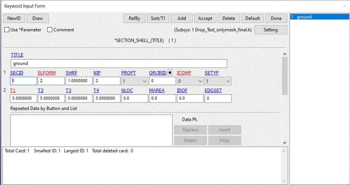
5. First, we need to assign Section id for both mobile and ground. By clicking Model & part>keywords>all>section>shell for ground. Now assign values and click accept and done.
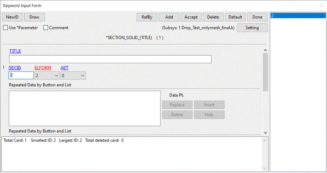
6. Now assign section id for solid mesh by clicking Model & part>keywords>all>section>solid. Now assign values and click accept and done.
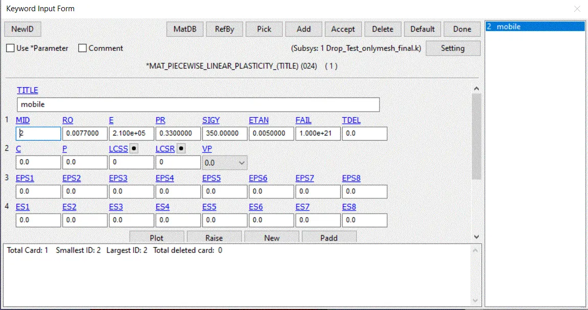
7. To create material cards for both mobile and ground. By clicking Model & part>keywords>all>MAT>Mat-24 piecewise >assign values of (material id, RO, YOung’s modulus, Poisson’s ratio, ETan, SigY)>accept>done. Here we assigned steel material values for the material card.
8. Similarly, we should assign a material card for the ground by selecting Rigid material in Model & part>keywords>all>MAT>Mat-20 Rigid >assign values of (material id, RO, YOung’s modulus, Poisson’s ratio)>accept>done.
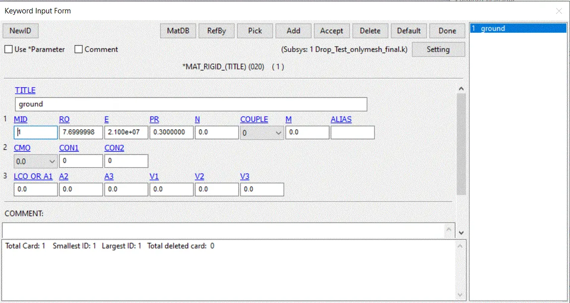
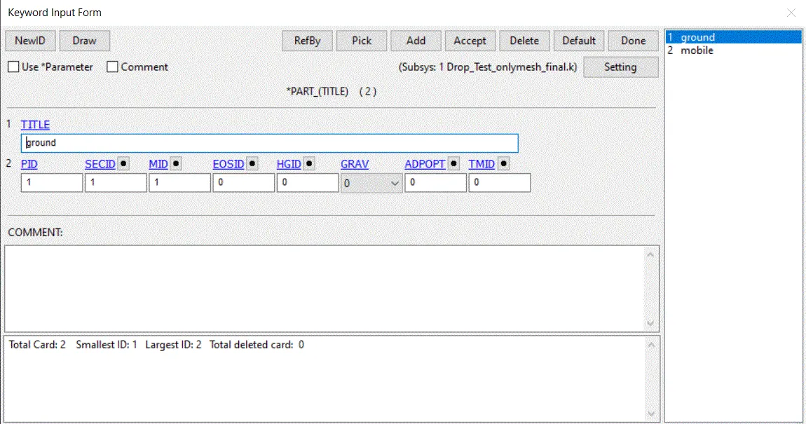
9. Now assign material and section cards for the parts using Model & part>keywords>Part>assign SECID, MID(mobile and ground)>accept>done.
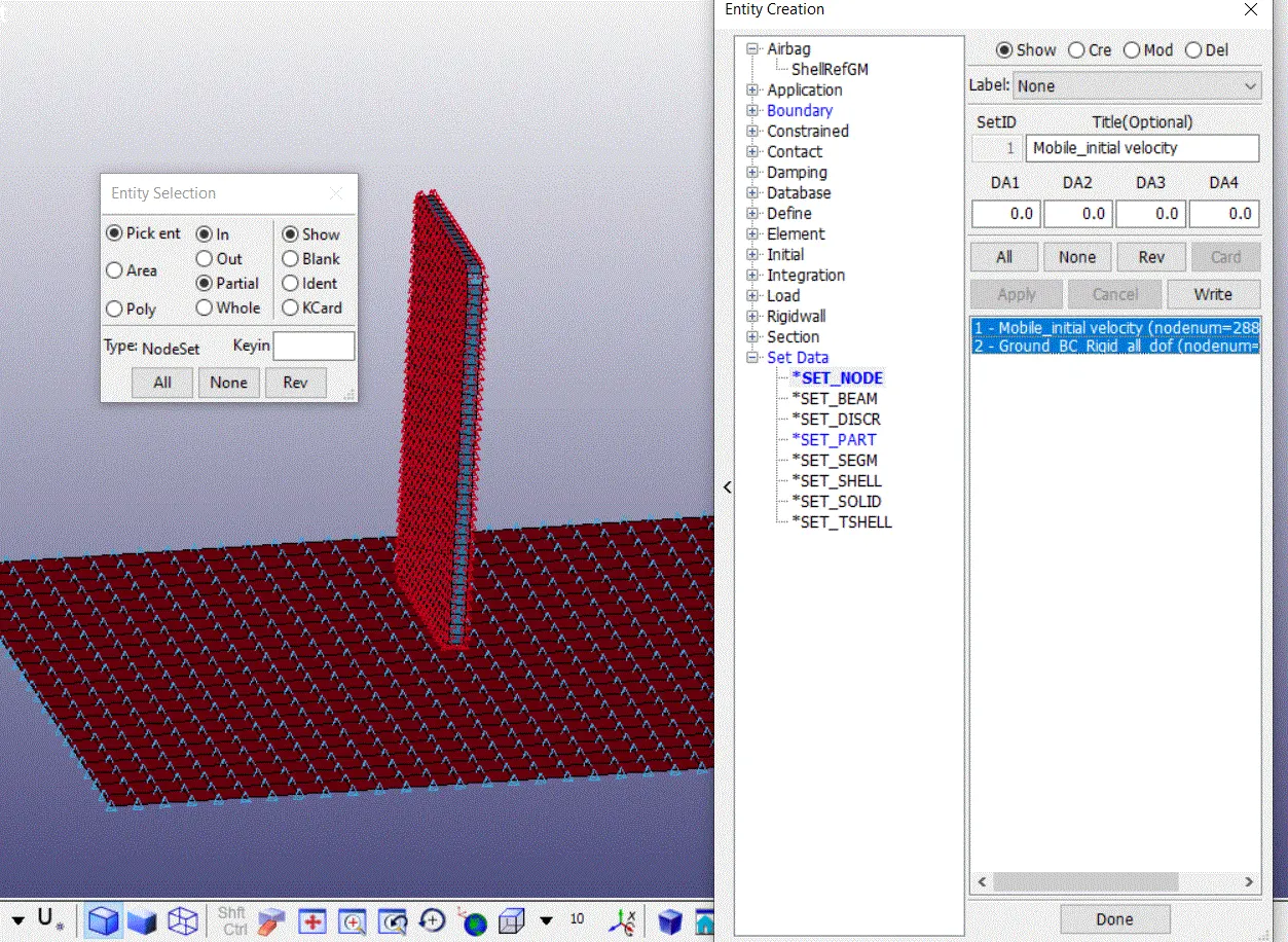
10. For Node set id creation, go to Model & part>Create entity>create>pick by part>assign a title and set id>apply>done. We need to assign set id and title and then pick the nodes using by part tool. After that click apply and done.
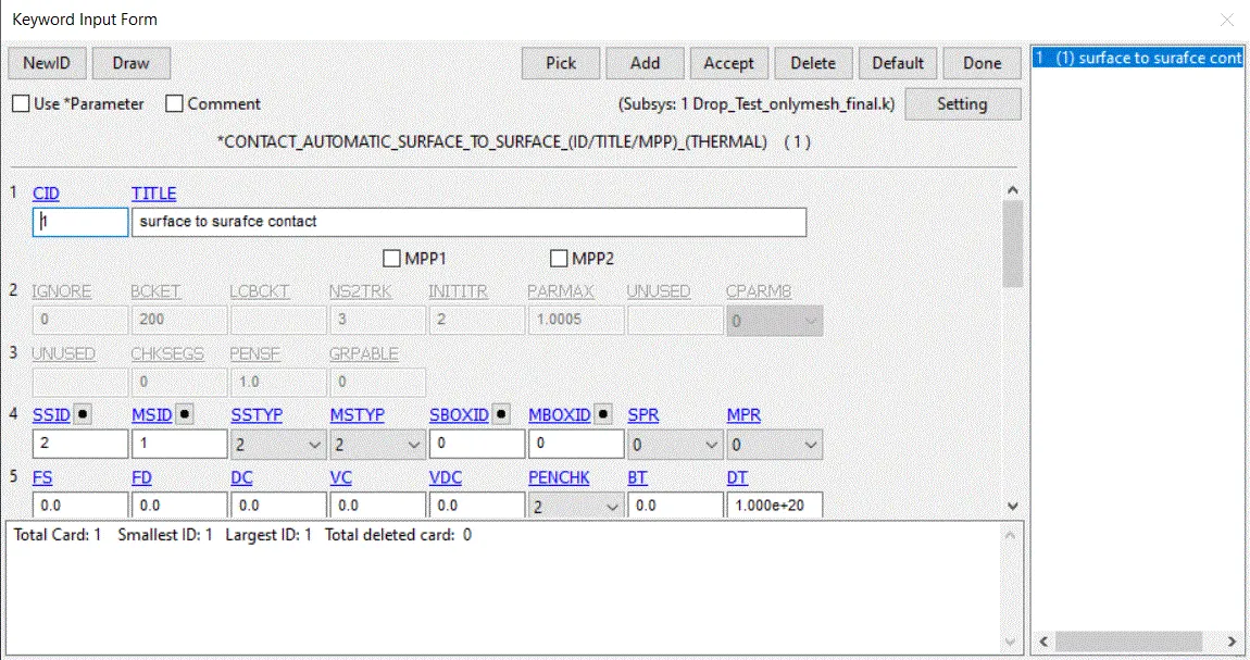
11. Now we should create a contact card for both parts. We need to make contact between ground and mobile using Model & part>keywords>all>Contact>automatic surface to surface> assign Slave node-set d and master node set id and SSID type and MSID type as 3. It is used to select the node-set using part id.
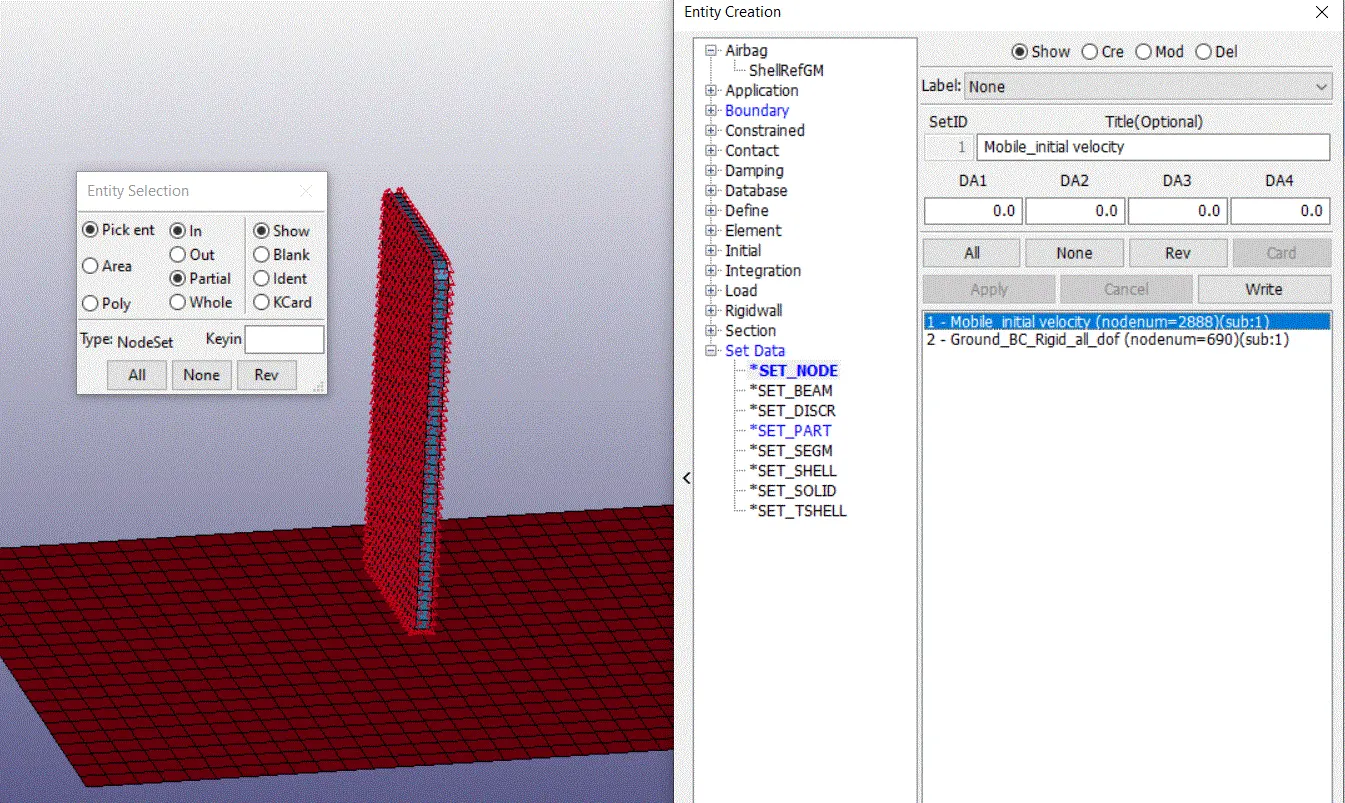
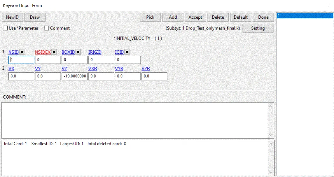
12. Similarly, We need to create a Node set to assign initial velocity for the mobile. Follow the same procedure for node-set creation. Now assign initial velocity using Model & part>keywords>all>Initial>velocity. Now assign Node set id and Velocity at Z-axis as -10mm/ms. Now click accept and done.
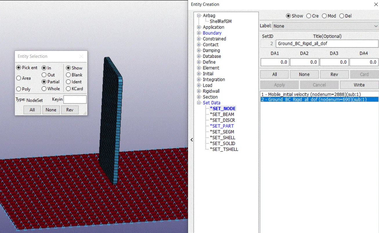
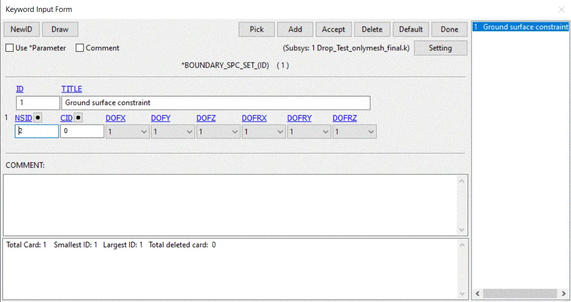
13.We need constraint the ground part in all directions for rigid by using single Boundary>spc by clicking Model & part>keywords>all>Boundary>spc. Assign values of Node set id and all directions as type 2 for constraint all the directions.
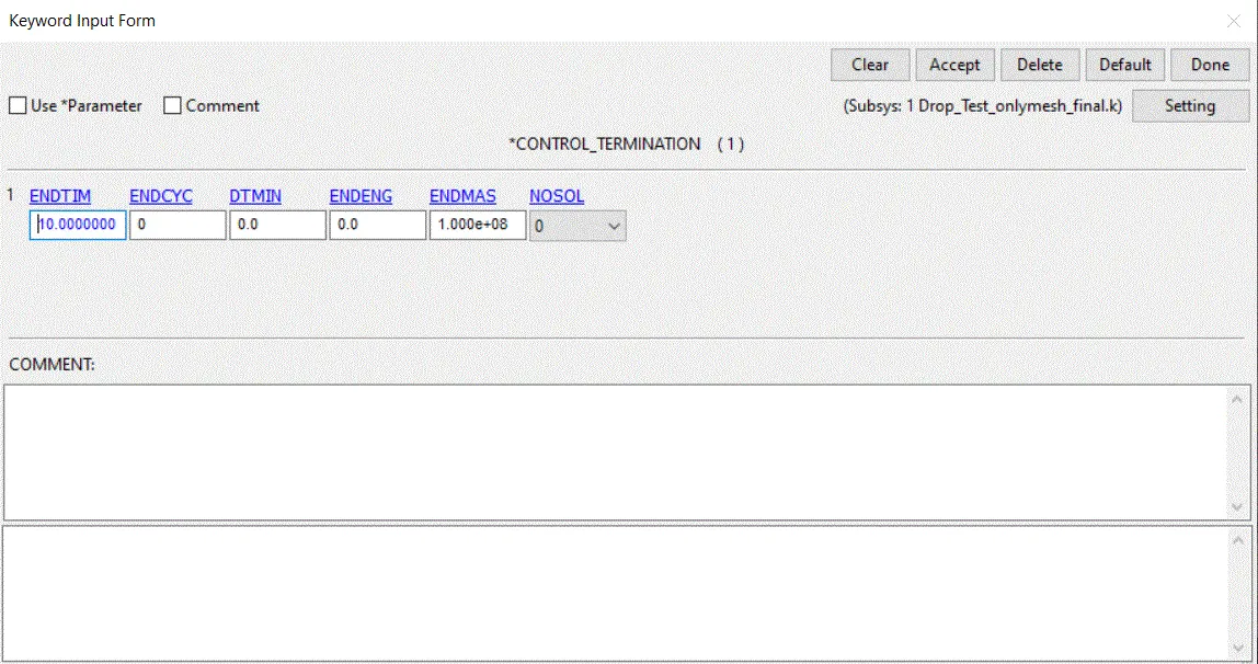
14. Then we need to create a control termination card using Model & part>keywords>all>Control>termination. Now assign termination time as 10ms. After that accept and done.
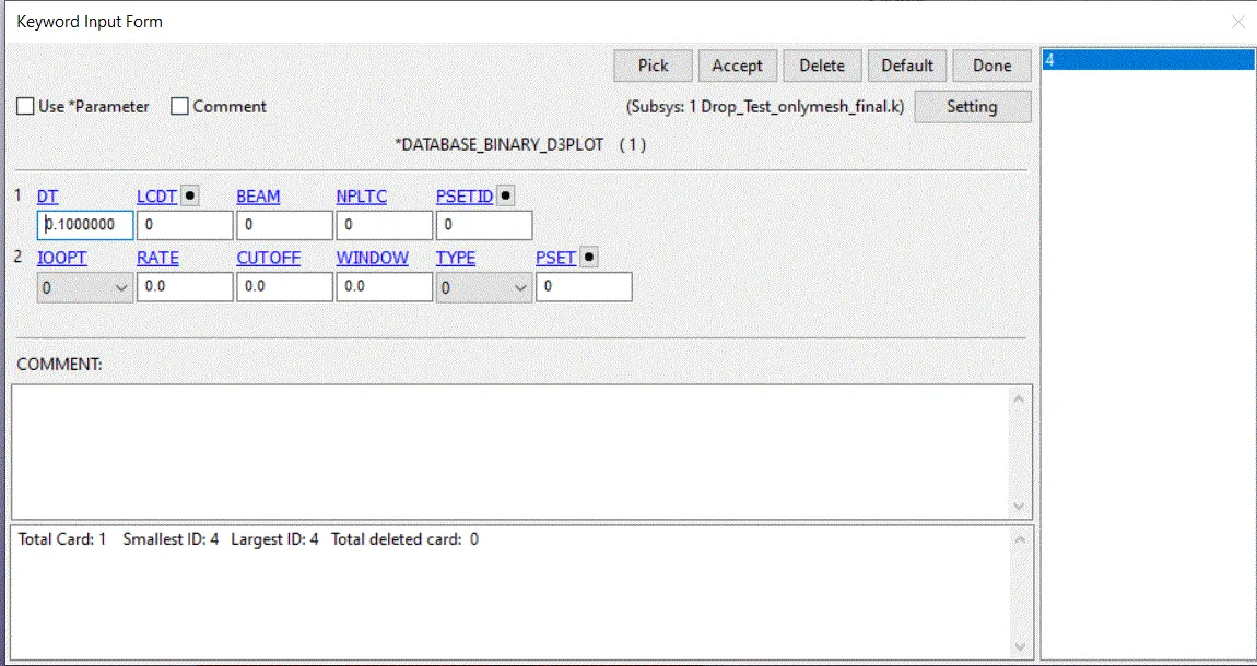
15. We should request for animation of the simulation using Model & part>keywords>all>Database>D3plot. Here we assign DT as 0.1ms for the time interval of the animation to be recorded.
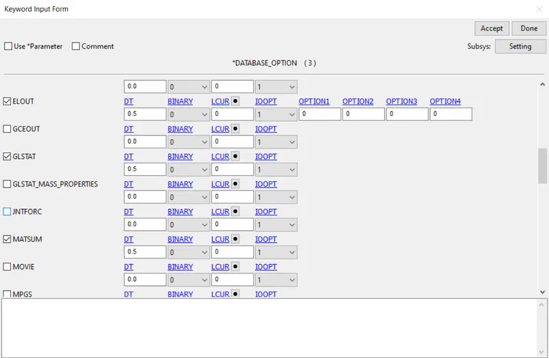
16. We need to generate plots of the energies of the model. For this we need to request for GLSAT using Model & part>keywords>all>Database>ASCII option. Assign DT value as 0.5ms time interval.
17. Similarly, we can request for the individual part energies using MATSUM by clicking Model & part>keywords>all>Database>ASCII option. Here assign DT value as 0.5ms time interval.
Post processing Results:
open LS-Prepost. NOw open>LS-Dyna binary plot. D3plot file in the same directory folder. After open the file, we need select Post>frige component>stress>von-mises stress>Apply. Now the animation file shown in the below.
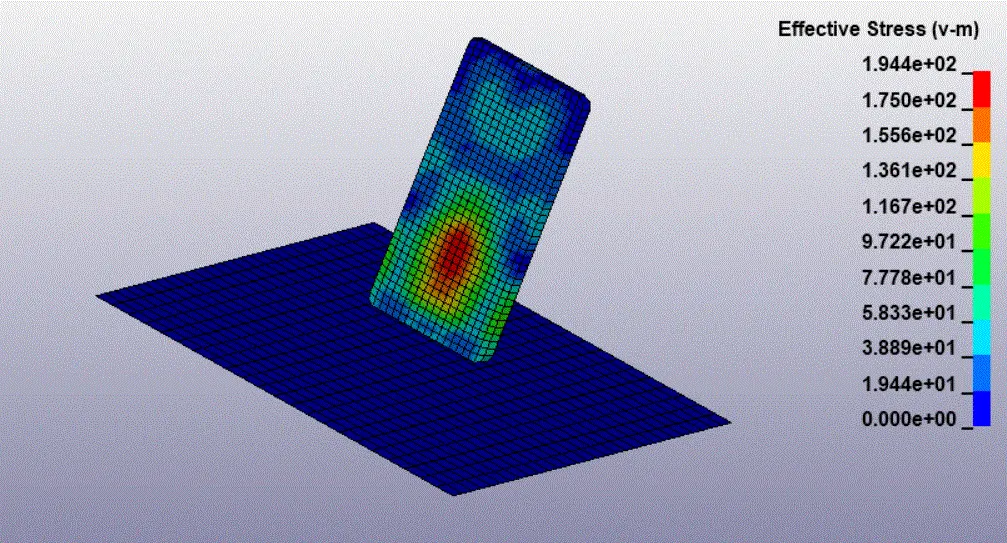
The maximum stress obtained at the impact area at 0.194Pa as per the unit system followed(gm,mm,ms). The Impact area of the mobile got maximum stress and the stresses were transferred to the other area of the mobile due to the vibrations of the impact. As we expected the top area of the mobile didn't have much stresses. The kinetic energy of the mobile was converted into the internal energy during the impact.
Now open ASCII tool in Post>ASCII plot. Now select the energies graph to plot for the graph. Select GLSAT and MATSUM. Load the respective files. now choose the energies we need to plot. Now select plot.
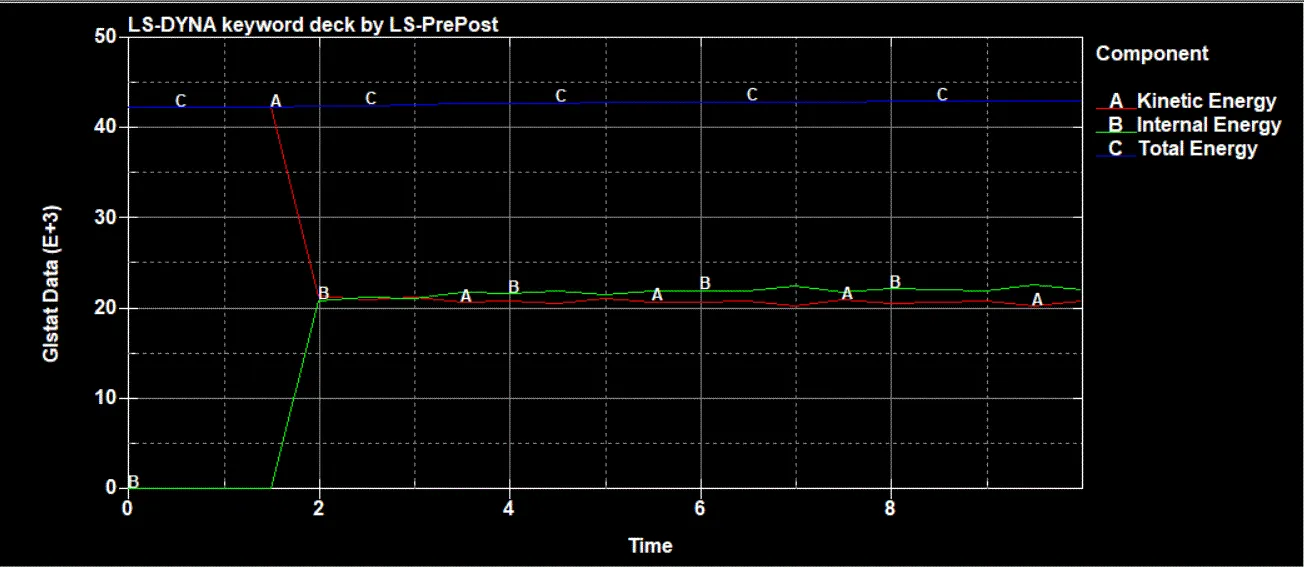
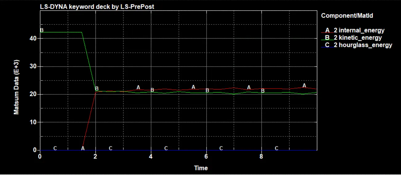
The graph shows that the kinetic energy of the mobile drops suddenly when the mobile got impact at 1.5ms. After that kinetic energy got absorbed as internal energy by the mobile. the plot show that the kinetic energy was completely transferred as a internal energy. After 2ms, the energies were get constant due to the rebound at the air. The maximum internal energy is at 20N-mm.
Conclusion:
The mobile and the floor was setup for the simulation. The animation of the simulation was given above. The Output requests for GLSAT and MATSUM was assigned properly and the energy graphs were plotted above.