3D meshing for the given housing assembly as per given parameters using hypermesh.
Challenge 8: 3D mesh for the given components as per given parameters above.
Objective: Do the 3D mesh on the housing components,crank component and chassis assembly for the given element size, min & max length.
- element size- 5mm (for chassis & crank component use element size-6mm)
- minimum length- 2mm
- maximum length- 7mm
- tet collapse- 0.150
Procedure:
Housing assembly:
- In housing assembly, there are two components such as hub and cover.
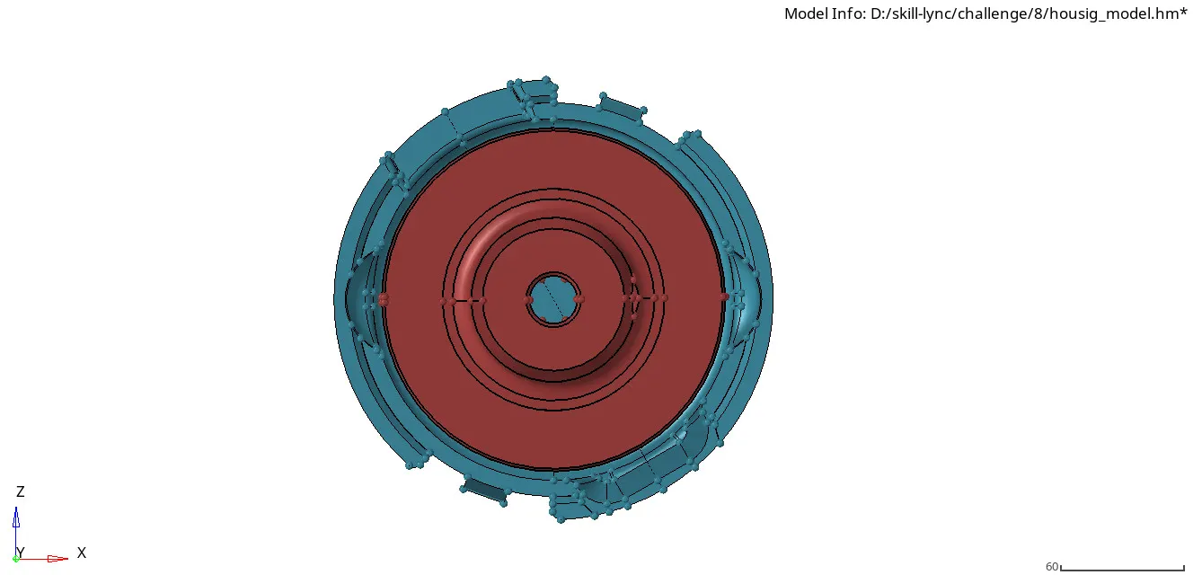
img.1 housing assembly
Hub:
- In 3D mesh, there are four method to do mesh. { first do 2D mesh and then use 2D shell elements to do 3D mesh, second directly do 3D mesh using volume tetra mesh, third do tetramesh using components which is enclosed component, fourth quick mesh in utility toolbar.
- now we can do two method, but we select volume tetra tool for that mesh as follows.
- first select 3d tool, then select tetramesh option and then select volume tetramesh(3d-tetramesh-volume tetramesh)
- now give the element size 5mm for the target and give trias for element type.
- now the mesh was created.we have to check the mesh for that select mask tool and then select elements to mask now we would see the tetra elements inside the mesh.
- finally we have to check for the tet collapse, select check elements-3d-tet collapse(0.150).
- now we cannot see the failed elements to see that select save failed in check elements tool and go to mask-elements(retrive)-mask-reverse. now we can see the elements failed.now cleanup the failed elements using distance tool manually.
- finally check the quality and tet collapse will be result in 0%
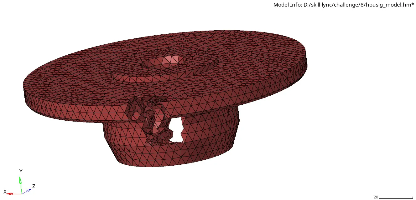
img.2 3D tetra mesh of hub
Cover:
- Do the same process for the cover component as followed in hub component.
- check the quality and tet collapse will be in 0% for that component.
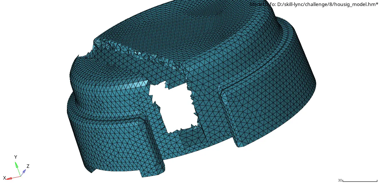
img.3 3D tetra mesh of cover
Crank component:
- first import the model.now delete the solids using delete-solids tool.
- now the geometry will appear, do the geometry cleanup manually.
- toggle the lines for the minimum surface length for minimum element size failed.
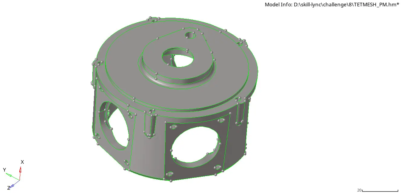
img.4 after geometry cleanup of crank component
- after geometry cleanup, the surface is ready for direct 3d mesh.
- now we can go for 2nd method, goto 3d-tetramesh-tetramesh tool
- select the component, then select element size-6mm and select mesh
- now select mask tool for see the tetramesh, now we should check for the tetcollapse.
- select the chck elements-3d-tet collapse(0.150)
- now select the failed elements and do mask the failed elements and reverse it.
- do the elements cleanup manually using distance or translate tool.
- after that check again, now the result will be shown as 0%.
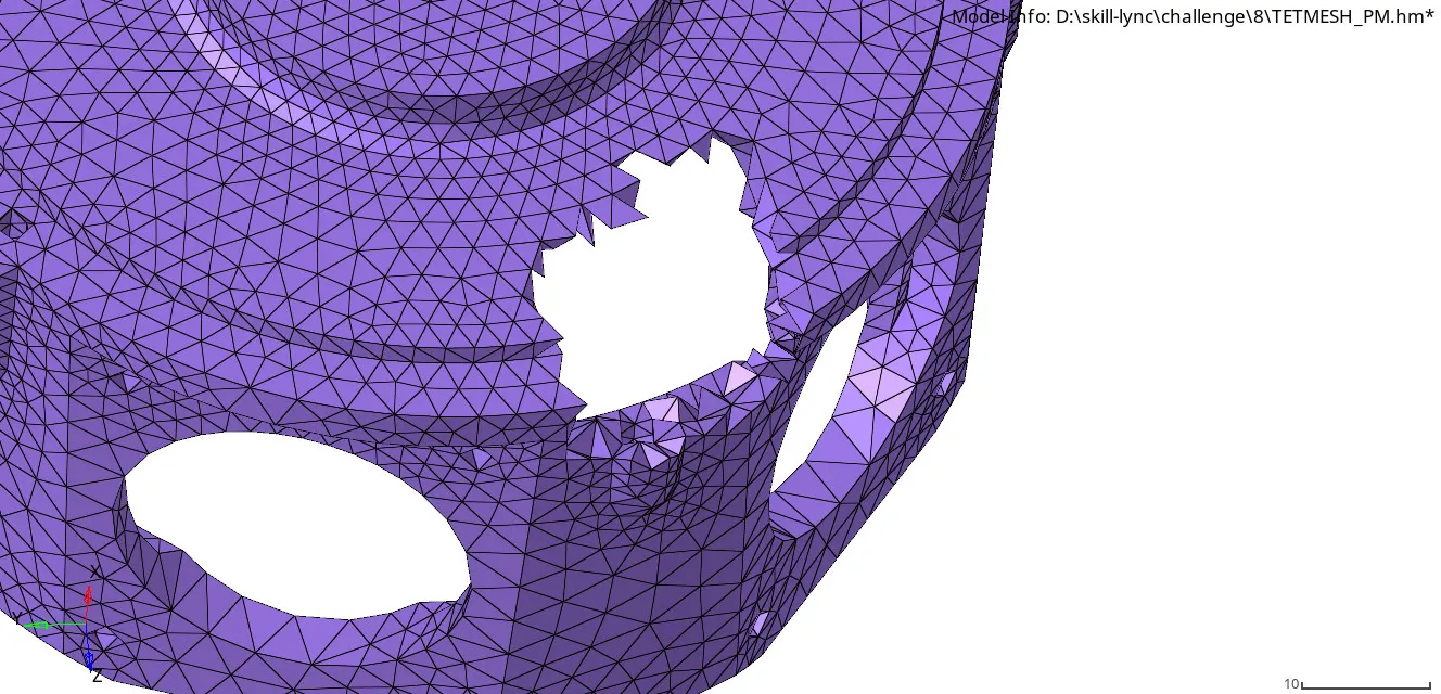
img.5 3D tetra mesh of crank component
Chassis assembly:
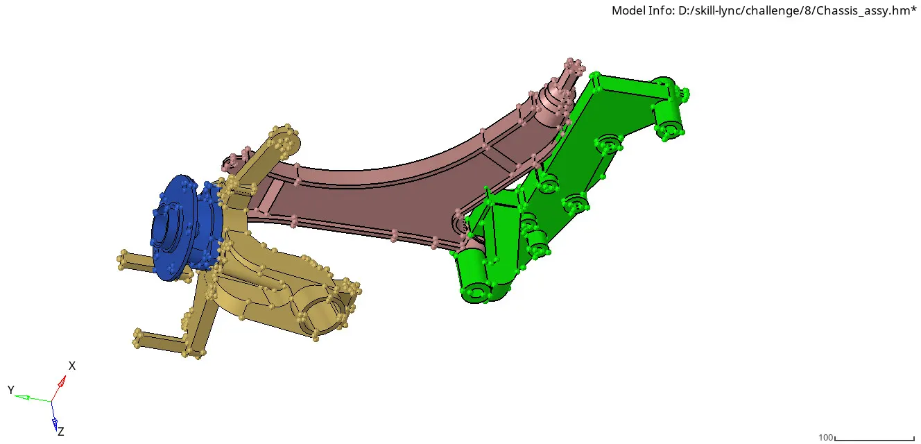
- there are eight components in the assembly but it had a symmetrical components for four components, so we can now mesh the four components and then reflect it.
 .
.
img.6 chassis assembly
component 1:
- Import the model, now delete the solids from the given geometry.
- now do the geometry cleanup for the model using topo view.
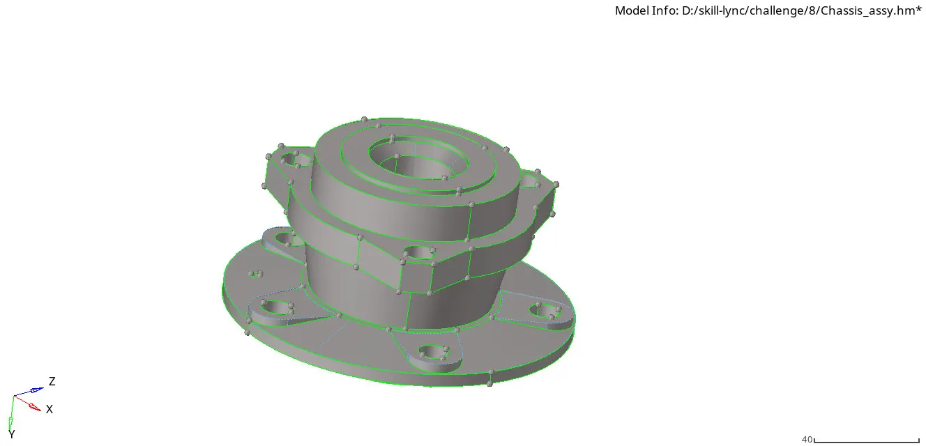
img.7 after geometry cleanup
- we can go for any method for 3d mesh but i was used first one, first do the 2D mesh for the geometry using element size 6mm and type trias.
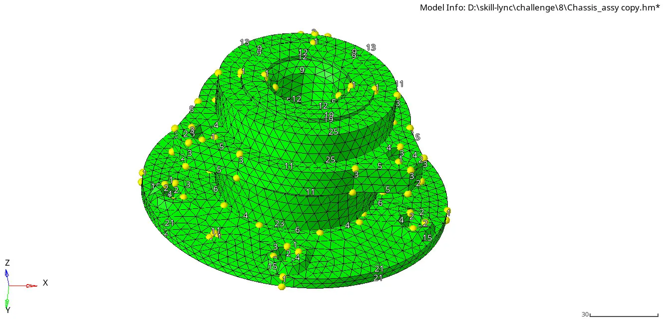
img.8 2D mesh for component 1
- after 2d mesh, check for quality of the mesh using minimum and maximum length of the element.
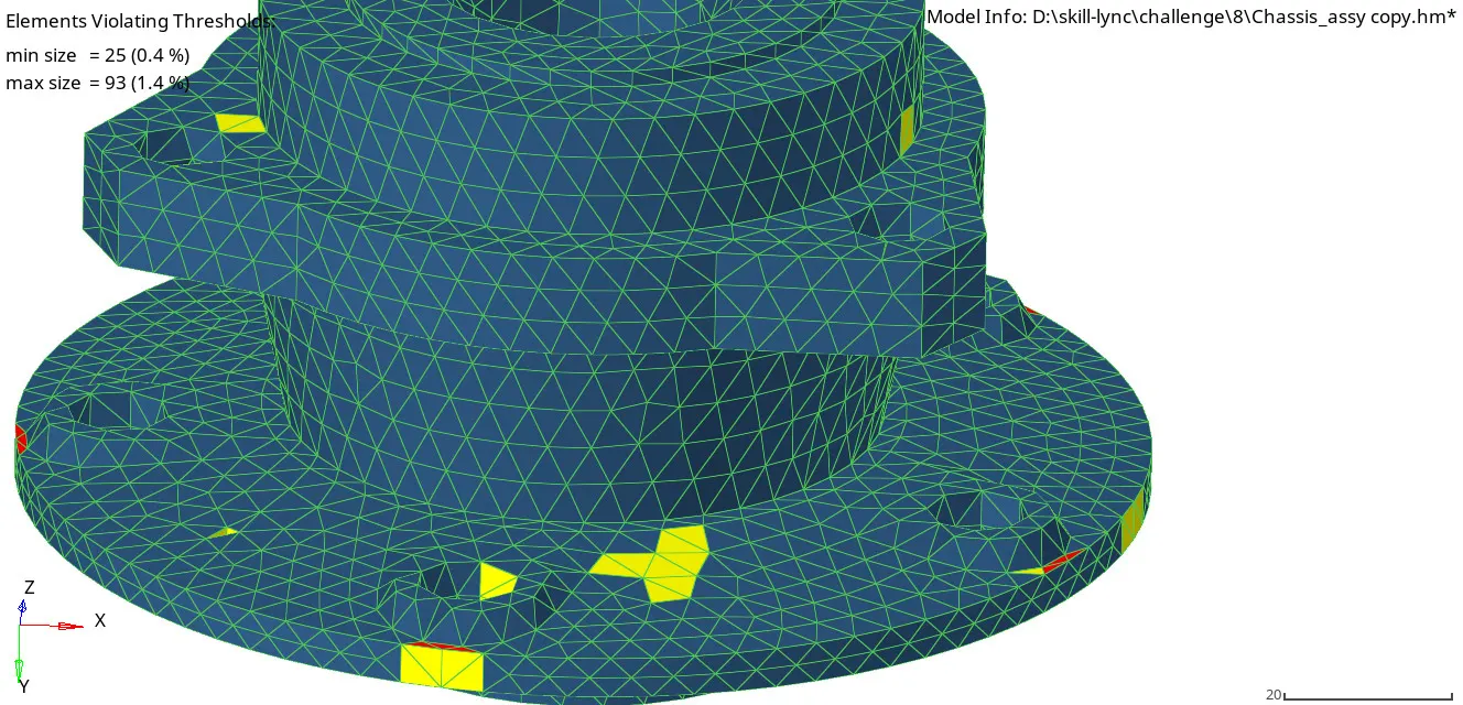
img.9 check for quality criteria
- after that go to 3d mesh, select tetramesh-elements, select the 2D shell elements that we created and now select mesh.
- after 3d mesh, check for tet collapse(0.150) in check elements and get the result as 0%.
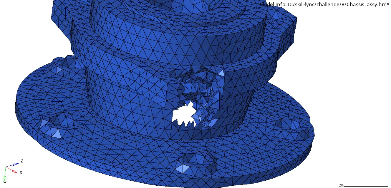
img.10 3D tetra mesh for component-1
component 2:
- now select the second component, we can go to do quick tetra mesh for this component.
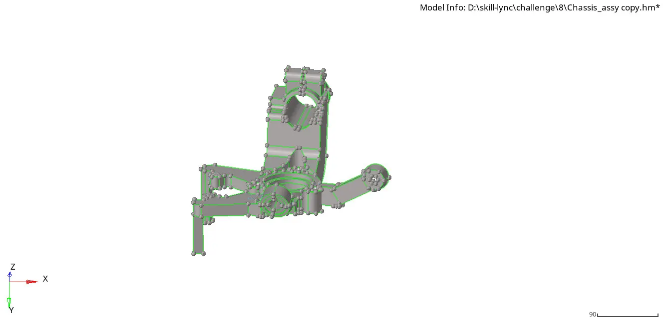
img.11 topo view of chassis component-2
- For that select view+browsers+hypermesh+utility+geo/mesh+quick tetra mesh tool.
- now give the element size as 6mm, minimum element size as 2mm, element type as trias only and then select mesh.
- after meshing, check 3d tetra elements using mask tool in quick mesh collector appeared in the specification tree below the component 2 collector.
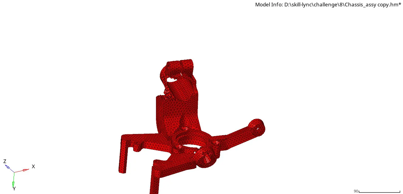
img.12 3d tetra elements of the component-2
- now check for tet collapse elements failed using check elements option.now correct the failed elements and get the result as zero.
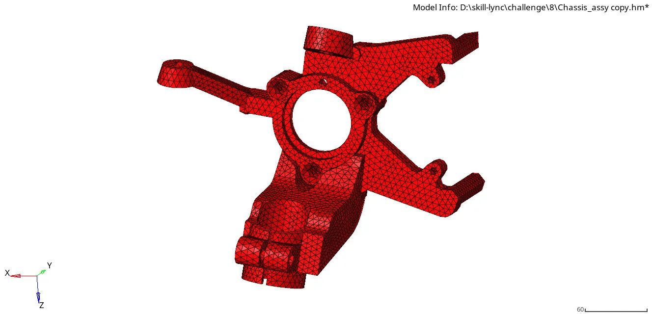
img.13 final 3D mesh of component-2
component 3:
- first select component 3,now directly go for 3D mesh.
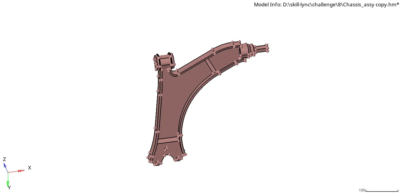
img.14 solid view of third component
- select 3D+tetra mesh+ volume tetra mesh+element size 6mm,minimum element size 2mm+select the solid+mesh.
- now the 3D tetra elements are created.as we saw by mask some elements for visible view of 3D elements.
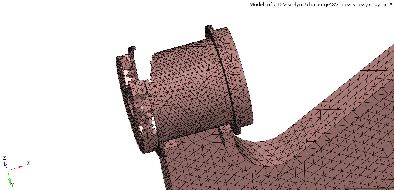
img.15 3D tetra elements view
- after the mesh, select the check elements tool for check failed elements for tet collapse(0.150).
- cleanup those elements and get the good 3d mesh by resulting as 0% tet collapse.
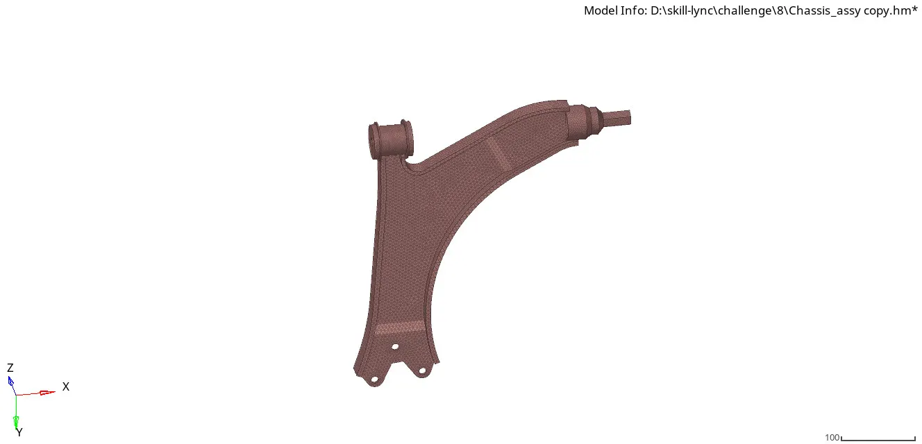
img.16 final 3D mesh of component-3
component 4:
- now delete the solids, go to quick edit panel to do geometry cleanup for the components.
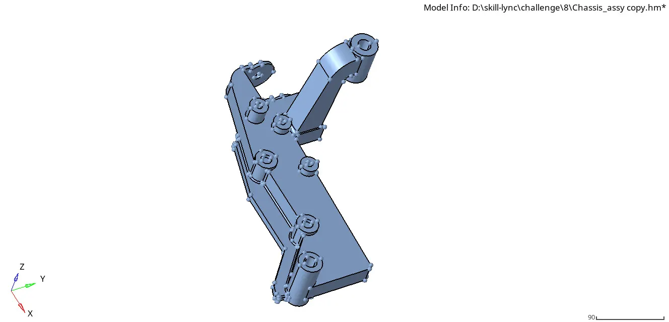
img.17 solid view of the fourth component
- now we go to do the third method, volume tetra mesh directly.
- go to tetra mesh-elements, select volume tetra mesh tool,then select element size 6mm and minimum element size 2mm and select mesh.
- we can see the 3d tetra element using mask option.
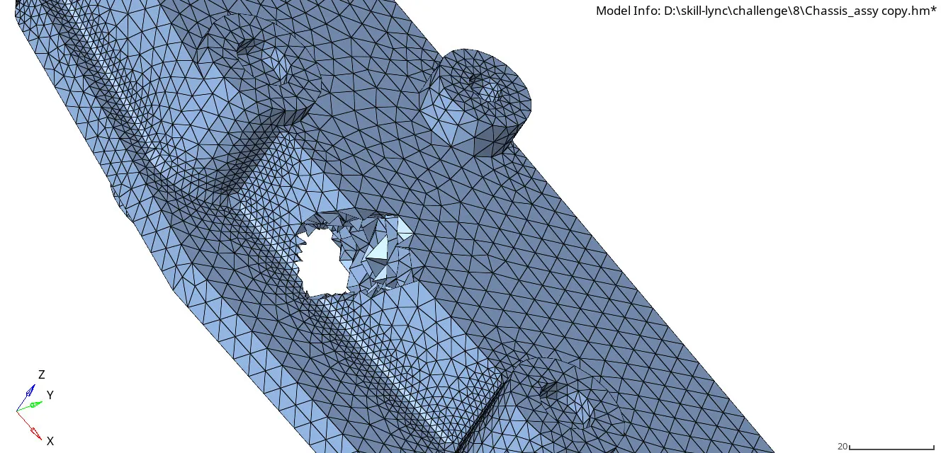
img.18 3D tetra elements view
- check for tet collapase (0.150) quality elements, now select the failed elements and correct it for the given parameters.
- now get the result as 0% for tet collapse.
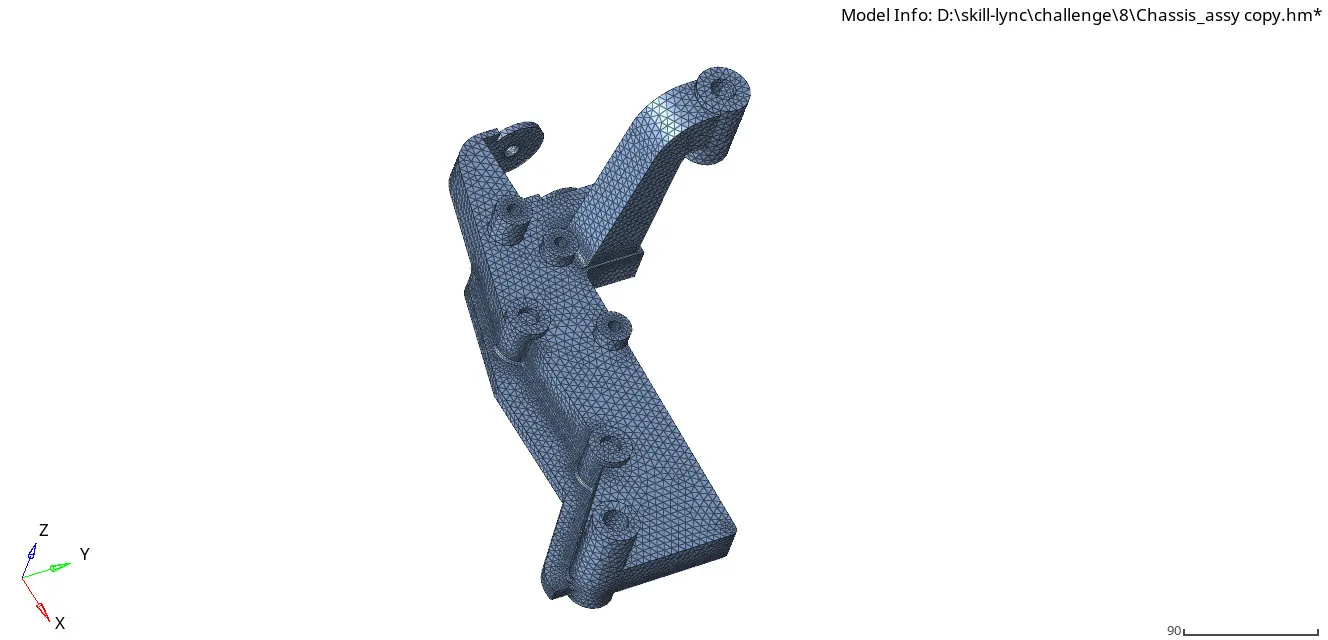
img.19 final 3D mesh of the component-4
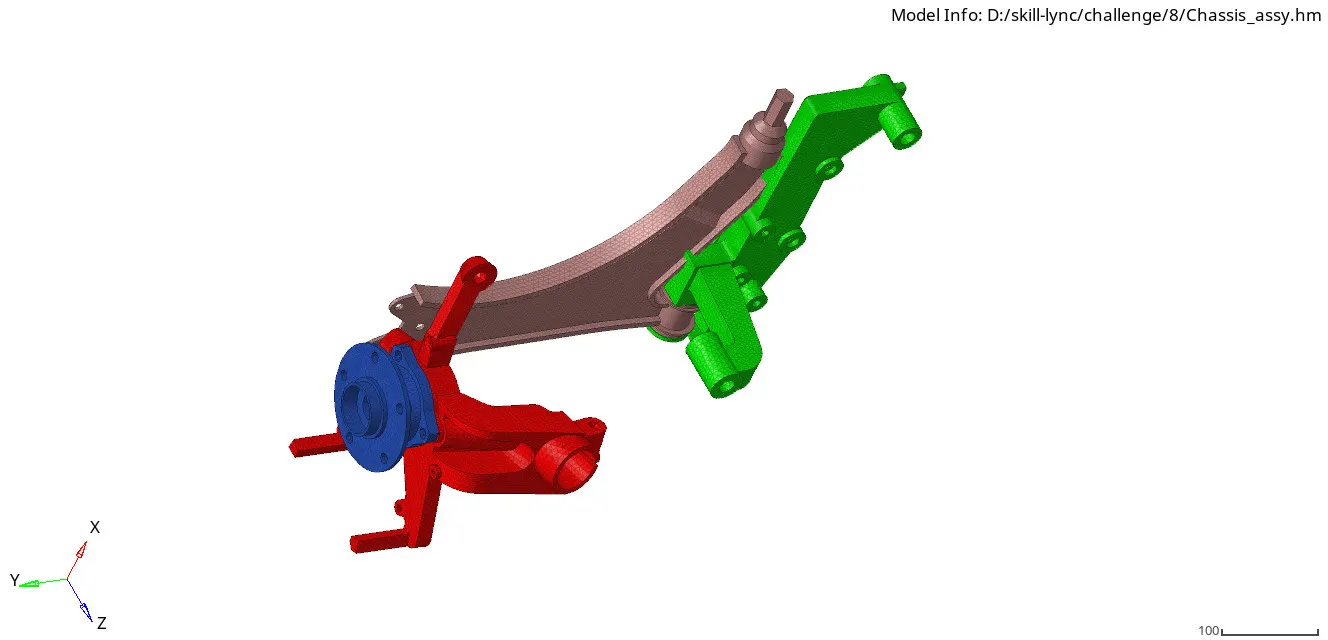
img.20 final 3D mesh of the chassis assembly
Note: while reflect the chassis components for symmetric components ,the node which exceed 100000 that error appear on screen, so we can done the mesh for one set of components.
Result & Conclusion:
- The housing and crank component are meshed directly in 3D mesh and the chassis components are meshed by 2D mesh first and after clean the failed elements for 2D mesh and do the 3D mesh as per given quality paramaters, now the result for quality failed elements is 0%.
- In this challenge,we must learnt that how to do 3D mesh for the complex components properly.
-------------------------------------------------------------------------------