Assignment 1
Objective:
The given geometries must be cleaned of any free edges, and the midsurface has to be extracted by neglecting small pinholes and fillets. Subsequently, the 2D mesh has to be created in accordance with the given quality criteria numbers and a property has to be assigned to each geometry.
Geometry - 1:
Step - 1: Geometry cleaning
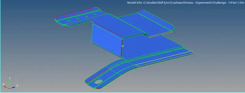
The given geometry has a few free edges and overlapping surfaces as shown below.
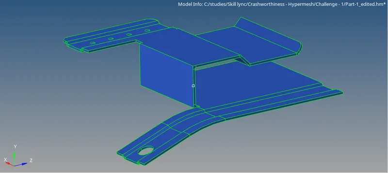
The geometry is cleaned and fillets less than a radius of 4 mm are removed. The final geometry which is ready for midsurface extraction is shown below.
Step - 2: Midsurface extraction
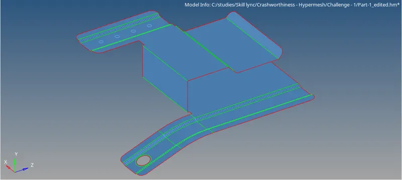
The midsurface is extracted from the above geometry and the pinholes (less than 5 mm dia) are removed. A washer split is also added around the larger hole at the bottom for better mesh capturing around the circular geometry.
Step - 3: 2D Mesh
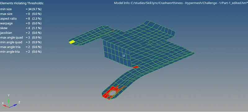
A 2D mesh is generated with shell elements with an element size of 5mm. The washer split is meshed first and the rest of the geometry is meshed in the next step with mesh connectivity.
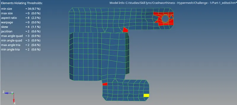
The mesh elements are refined to reduce the number of failure elements and finally optimized until the number of failed elements are less than 10% as shown below.
Step - 4: Property assignment
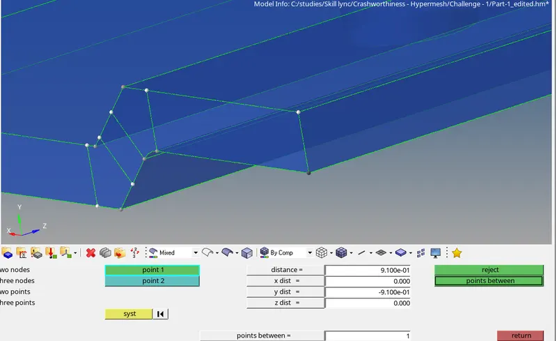
The thickness of the part is measured using the distance option (as shown below) and a property is created with the same thickness (0.9 mm).
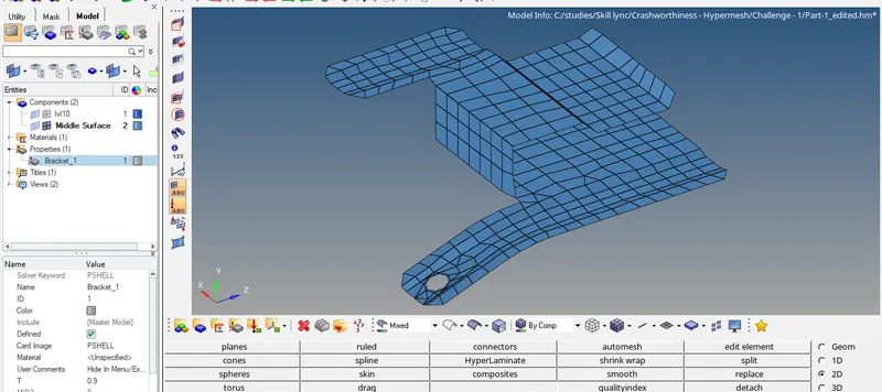
The card image is PSHELL using Optistruct solver profile, since the elements in question are shell elements.
Geometry - 2:
Step - 1: Geometry cleaning
The original geometry is shown below.
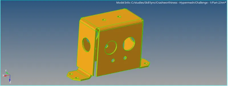
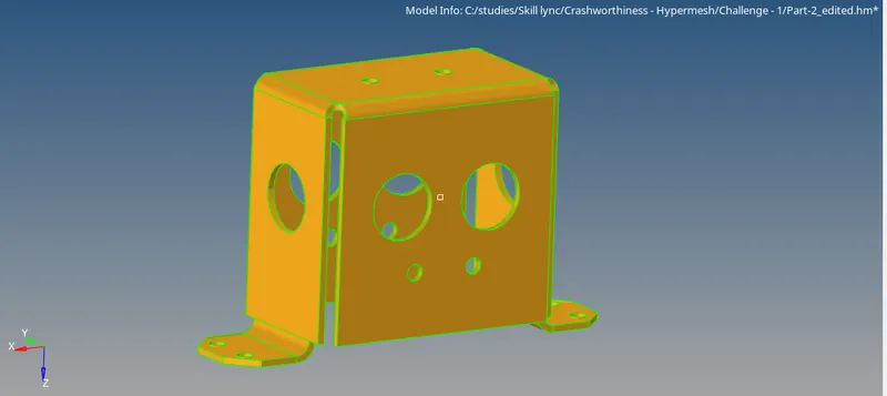
The geometry is cleaned and the unnecessary edges are toggled for a smoother mesh generation. The surfaces at the top contain two edges really close to each other, which are equivalenced. The final geometry which is ready for midsurface extraction is shown below.
Step - 2: Midsurface extraction
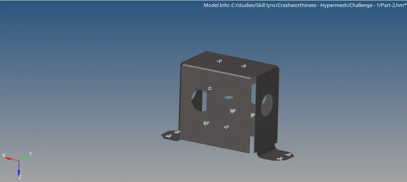
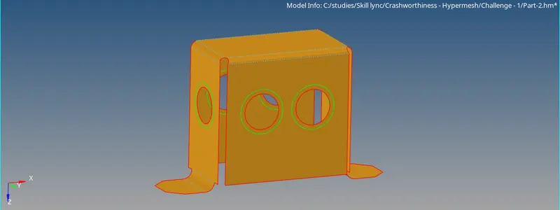
The midsurface is extracted from the above geometry and the pinholes (less than 5 mm dia) are removed. A washer split is also added around the holes for better mesh capturing around the circular geometry.
Step - 3: 2D Mesh
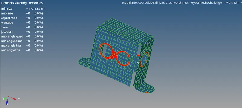
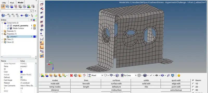
A 2D mesh is generated with shell elements with an element size of 5mm. The washer split is meshed first and the rest of the geometry is meshed in the next step with mesh connectivity.
The mesh elements are refined to reduce the number of failure elements and finally optimized until the number of failed elements are around 10% as shown below.
Step - 4: Property assignment
The thickness of the part is measured using the distance option (as shown below) and a property is created with the same thickness (2 mm).
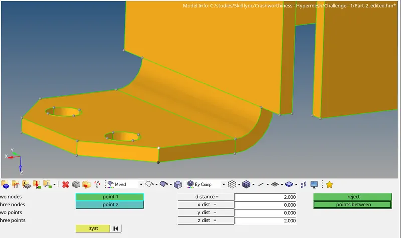
The card image is PSHELL using Optistruct solver profile, since the elements in question are shell elements.
Geometry - 3:
Step - 1: Geometry cleaning
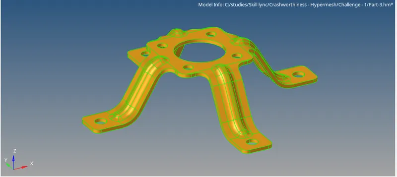
The original geometry is shown below.
Step - 2: Midsurface extraction
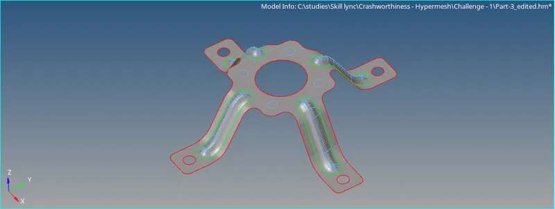
The midsurface is extracted from the above geometry and the pinholes (less than 5 mm dia) are removed from the top surface using filler surfaces.
Step - 3: 2D Mesh
A 2D mesh is generated with shell elements with an element size of 5mm. The curved surfaces are meshed first and the rest of the geometry is meshed in the next step with mesh connectivity.
The mesh elements are refined to reduce the number of failure elements and finally optimized until the number of failed elements are around 25% as shown below. The elements at the end-plates fail to meet the minimum element size criteria of 3.5 mm because of the size of the geometry.
The number of fail-elements can be reduced, but it would lead to a worse mesh capturing of the four circular edges at the end-plates. Therefore, this mesh can be considered as the optimized final mesh.

Step - 4: Property assignment
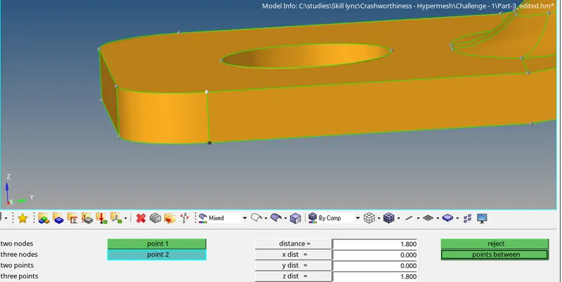
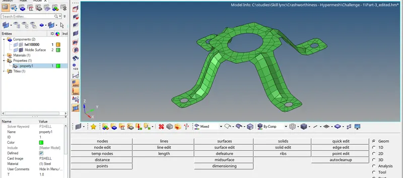
The thickness of the part is measured using the distance option (as shown below) and a property is created with the same thickness (1.8 mm).
The card image is PSHELL using Optistruct solver profile, since the elements in question are shell elements.
Conclusion
The three geometries are cleaned, midsurface is extracted and the mesh is optimized in order to meet the element quality criteria. The property for the geometry is also added according to the corresponding thickness.
The edited geometry files in the .hm format are added below.