Week-7 Head Impact
Objective:
To simulate the head impact using a simple head model and a headform against a simple rigid wall and a hood, and analyse the results.
Case 1: Impact of the Simple head model against the rigid wall
Step 1: Model setup with Section and Materials
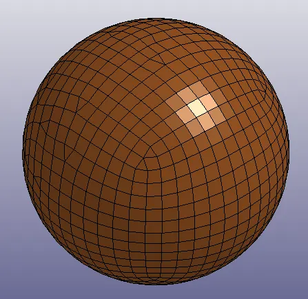
The simple head solid model is imported into LS Dyna as shown below.
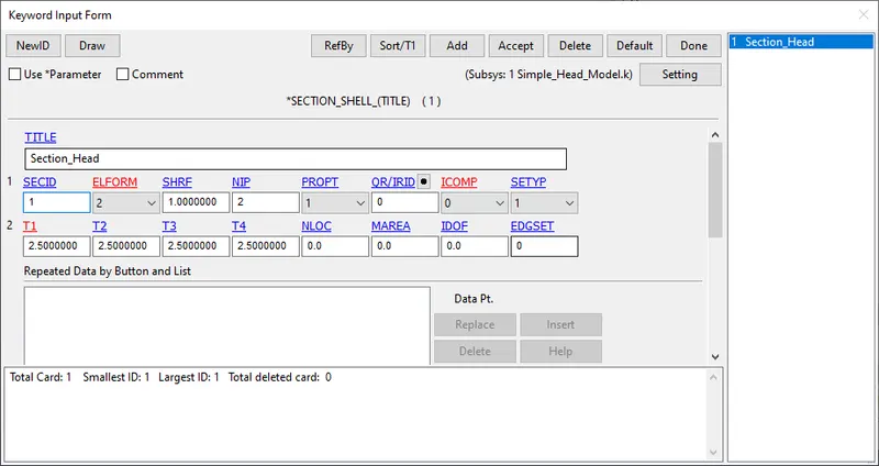
The model is defined with shell elements of ELFORM 2 and a thickness of 2.5 mm as shown below.
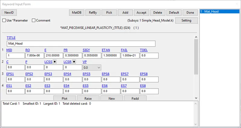
The model is defined with a piecewise linear plastic MAT - 24 card and the properties of steel are input as shown below. The unit system is kg-mm-ms.
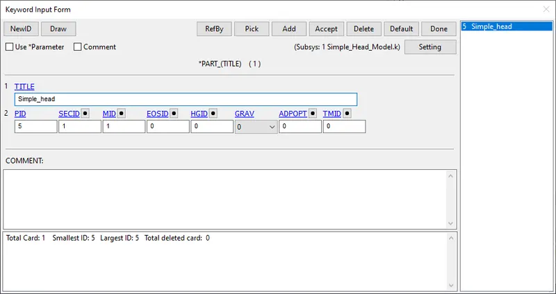
The section and the material are assigned to the head part ID as shown below.
Step 2: Boundary conditions
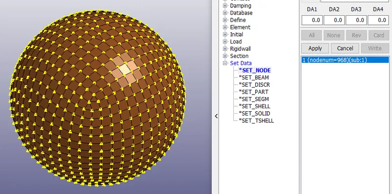
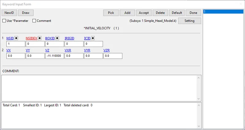
The nodes of the model are selected and an initial velocity of 11.11 mm/ms corresponding to a speed of 40 km/hr is appied to them in the negative Z direction.
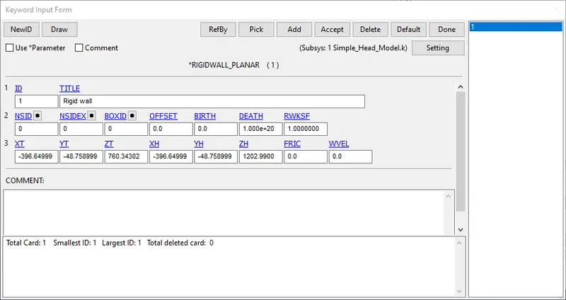
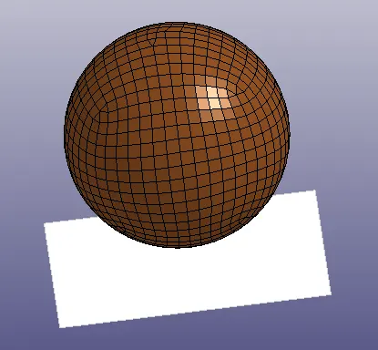
A rigid wall is created at a distance of 15 mm from the bottom of the simple head with co-ordinates as shown in the figure below.
Step 3: Control and Database cards
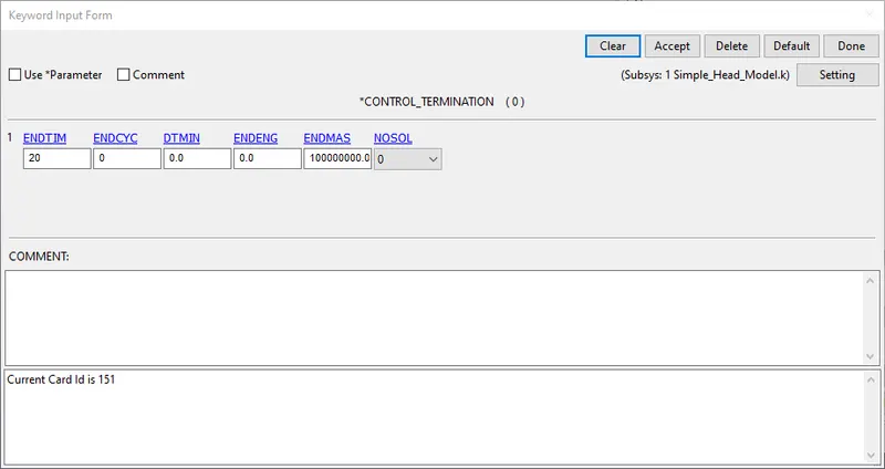
The simulation is setup to run for 20 ms as shown below
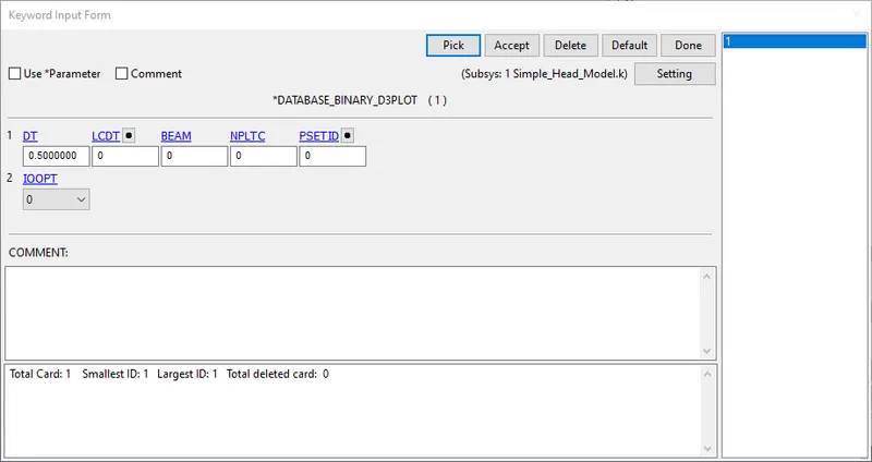
Under the DATABASE cards, BINARY_D3PLOT is selected with a DT of 0.5 ms
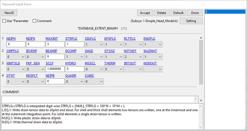
The EXTENT_BINARY card is used with the STRFLG = 1, in order to write out the computed strain data in the output file.
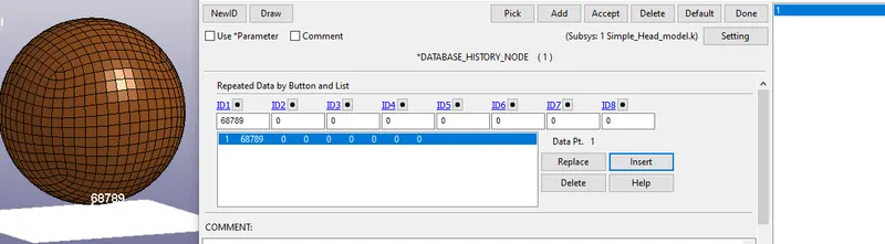
In order to investigate the effects of impact, a node at the bottom is selected (ID:68789)
In addition, under DATABASE_ASCII, GLSTAT, RWFORC and NODOUT are selected with a DT of 0.5ms.
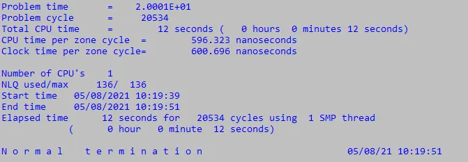
The simulation is run using the solver and checked for normal termination
Case 2: Child head foam against rigid wall
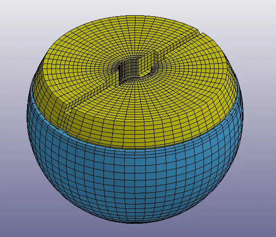
The file PEDESTRIAN_HEADFORM is imported into LS-DYNA as shown below.
Step 1: Defining Incude and Transformation
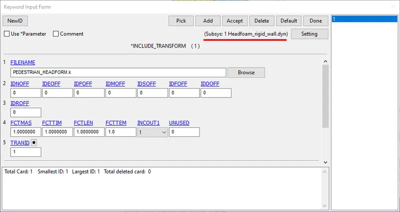
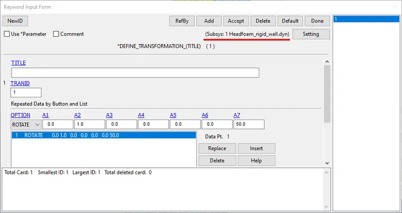
A new model is created and the INCLUDE_TRANSFORM and DEFINE_TRANSFORMATION cards are specified as shown below in order to rotate the model about the Y axis by 50 degrees. Then the new model is saved under a new name (Here:Headfoam_rigid_wall.dyn)
On reopening the model, the headform is rotated by 50 degrees about the Y axis, in the right position for simulating the head impact.
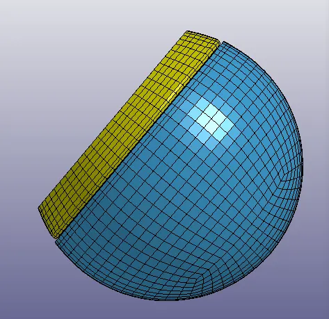
The further cards used to setup the simulation should be under the Headfoam_rigid_wall.dyn subsystem.
Step 2: Boundary condition
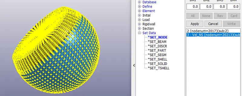
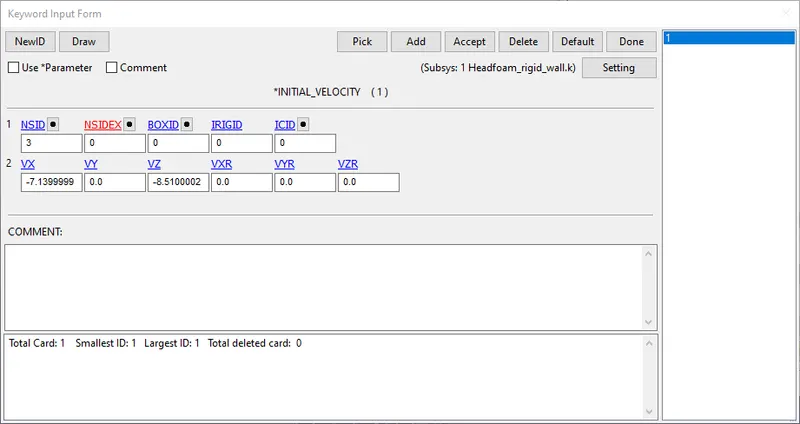
The nodes of the model are selected and an initial velocity of 40 km/hr is applied to them. Since the impact occurs at an angle, the velocity is resolved into its components of -7.14 mm/ms along the negative X and -8.51 mm/ms along the negative Z directions respectively, as shown below.
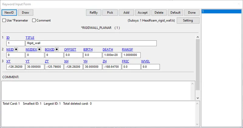
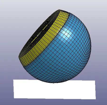
A rigid wall is created at a distance of 15 mm below the headform as shown below.
Step 3: Control and database cards
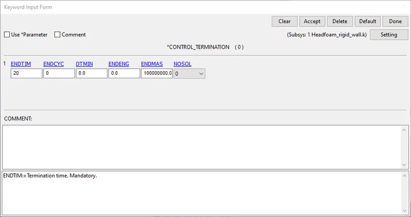
The simulation is setup to run for 20 ms as shown below
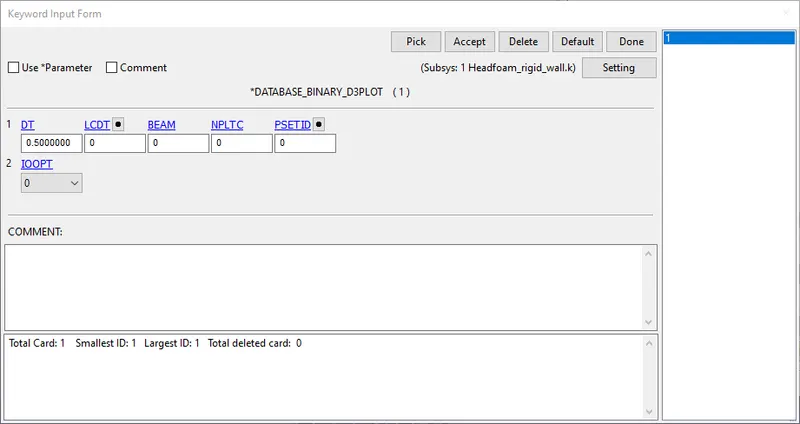
Under the DATABASE cards, BINARY_D3PLOT is selected with a DT of 0.5 ms
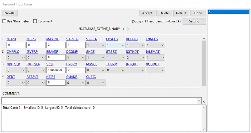
The EXTENT_BINARY card is used with the STRFLG = 1, in order to write out the computed strain data in the output file.
In addition, under DATABASE_ASCII, GLSTAT, RWFORC and NODOUT are selected with a DT of 0.5ms.
The simulation is run using the solver and checked for normal termination.
Case 3: Child head form against Hood
The meshed hood model is opened in LS-Dyna as shown below.

Step 1: Defining Incude and Transformation
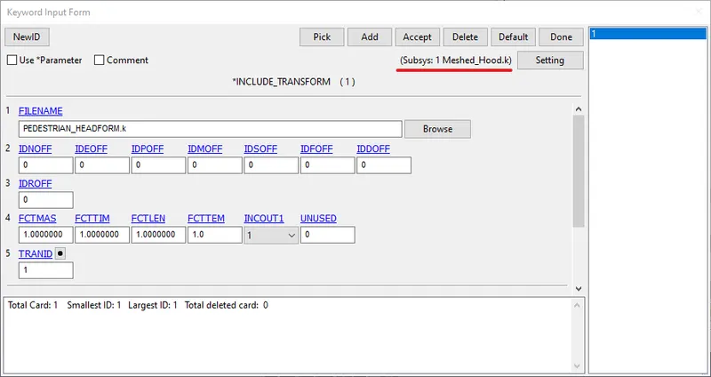
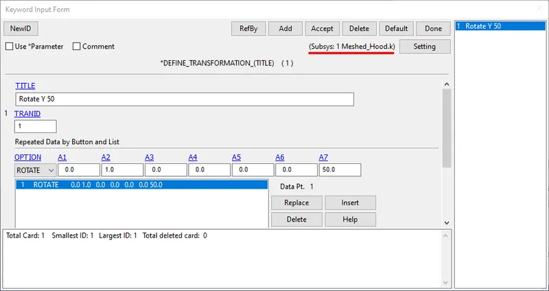
A new model is created and the INCLUDE_TRANSFORM and DEFINE_TRANSFORMATION cards are specified as shown below in order to rotate the model about the Y axis by 50 degrees. Then the new model is saved under a new name (Here:Meshed_Hood.k)
Step 2: Section and material definition
1. Steel
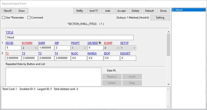
The hood is defined with SHELL elements of ELFORM 2 and a thickness of 2 mm as shown below.
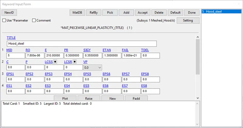
The model is defined with a piecewise linear plastic MAT - 24 card and the properties of steel are input as shown below. The unit system is kg-mm-ms.
2. Aluminium
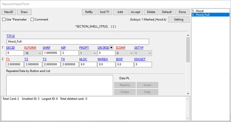
The hood is defined with SHELL elements of ELFORM 16 and a thickness of 2 mm as shown below.
The model is defined with a piecewise linear plastic MAT - 24 card and the properties of aluminium are input as shown below. The unit system is kg-mm-ms.
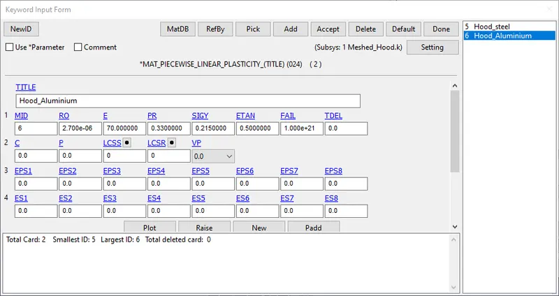
The model is simulated for both materials and ELFORMS and the results of the HIC are compared.
Step 3: Boundary conditions
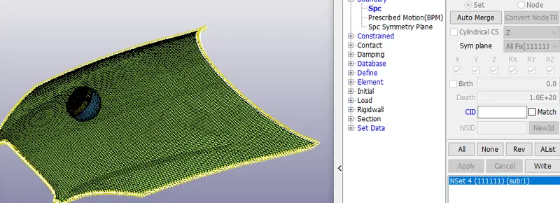
A SPC (single point constraint) is applied to the outer edges of the hood in all 6 directions, in order to constrain hood motion and keep it fixed.
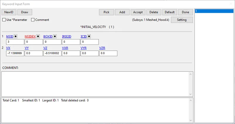
The nodes of the model are selected and an initial velocity of 40 km/hr is applied to them. Since the impact occurs at an angle, the velocity is resolved into its components of -7.14 mm/ms along the negative X and -8.51 mm/ms along the negative Z directions respectively, as shown below.
Step 4: Contact, control and database cards
An automatic surface to surface contact is applied between the Skin of the headform and the hood.
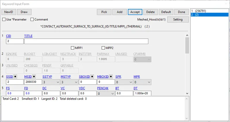
Since the materials of the parts coming in contact vary a lot in their properties, the contact definition is done using a SOFT formulation as shown below.
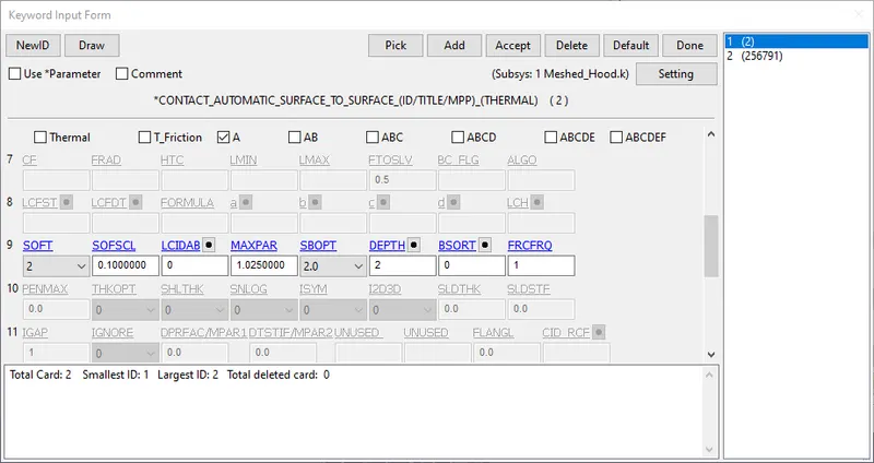
The control and the database cards are defined using the same parameters as Case 2.
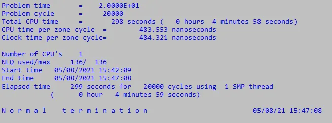
The simulation is run using the solver and checked for normal termination.
Results
The animation of the effective (von mises stress) and the effective plastic strain for all the cases are shown below.
Case 1: Simple head model against rigid wall

Case 2: Headform against rigid wall
Case 3: Headform against hood (Steel - Elform 2)
Case 4: Headform against hood (Aluminium - Elform 16)
In case 1, the maximum stress is 455 Mpa, which is greater than the yield stress of 355 Mpa. Therefore, the elements show permanent deformation, once the elastic limit has been crossed.
In case 2, the maximum stress is 3.953 MPA, which is much lesser than the elastic limit. The material of the foam is a Hyperelastic material with significant deformation, which makes the stresses smaller.
In case 3 with steel material (Elform 2), the maximum stress is 355.5 MPa, whereas with aluminium, the value is 220 MPA, both of which are close to the elastic limits.
Energy plots
The energy plots for all the cases are analyzed below
Case 1: Simple head model against rigid wall
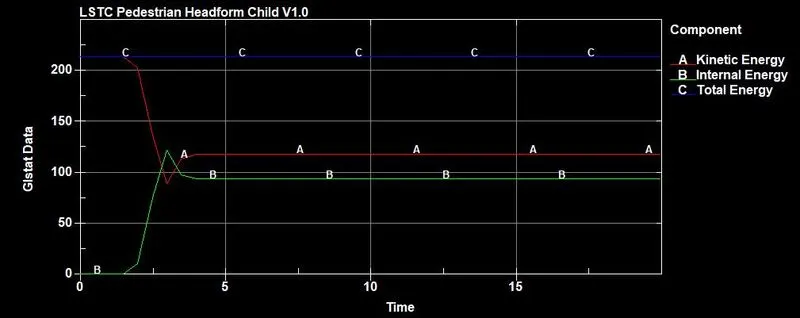
Case 2: Headform against rigid wall
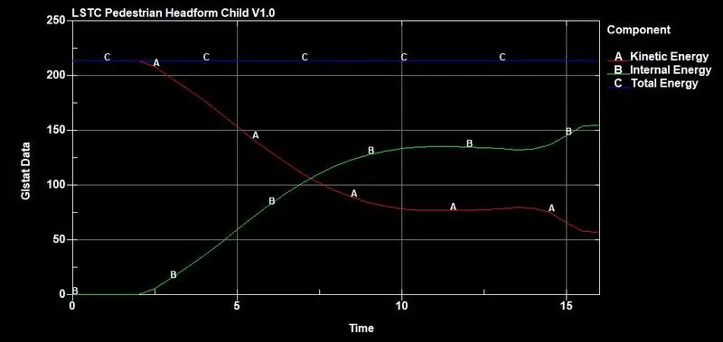
Case 3: Headform against hood (Steel - Elform 2)
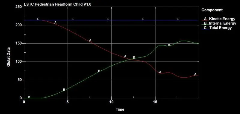
Case 4: Headform against hood (Aluminium - Elform 16)
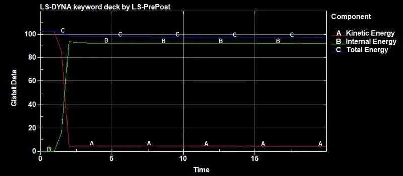
The energy plots of cases 1 and 2 show a sudden drop of kinetic energy and a corresponding increase of internal energy at the instant of the impact with the rigid wall, mainly because the rigid wall is non deformable.
The energy plots of cases 3 and 4 show a more gradual change of energy, since the hood is defined with steel and aluminium materials and undergoes deformation on impact. The maximum value is just over 200.
HIC results
The HIC 15 is calculated according to the following expression
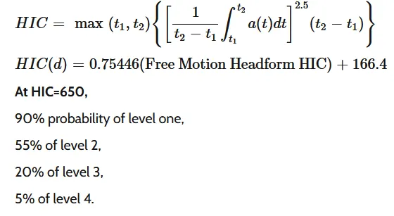
The HIC 15 results for all the cases are analyzed below
Case 1: Simple head model against rigid wall
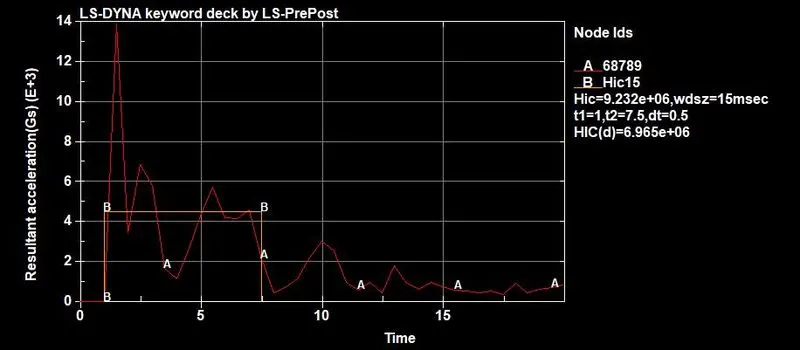
The HIC value for case 1 of 6.95 e+6 is above the recommended HIC value. The value is extremely high, mainly because impact occurs against a rigid plate, which is completely non-deformable.
Case 2: Headform against rigid wall
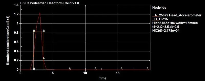
The HIC for case 2, where the child headform is used, shows a slightly lower value, since the headform material is more elastic compared to the simple head model and thereby undergoes more deformation. But the value of 2.17 e+4 is very high compared to the recommended HIC value of 650.
Case 3: Headform against hood (Steel - Elform 2)
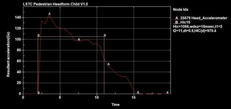
The HIC for case 3, where the hood is defined with steel material, is 970.4. Even though the hood is deformable, the high young's modulus of steel means that it has high stiffness, which leads to a higher damage to the head on impact.
Case 4: Headform against hood (Aluminium - Elform 16)
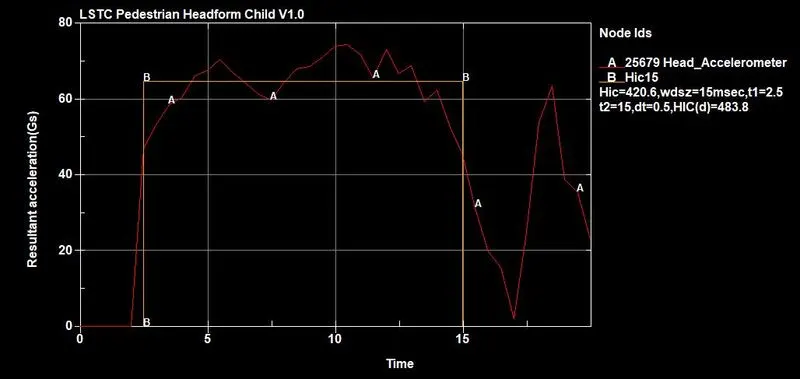
The HIC for case 4, where the hood is defined with aluminium, is 420.6 and the HIC (d) is 483.8, which is less than the safe HIC value of 650. This is because aluminium has a higher deforming ability and is less stiffer compared to steel, and the hood deforms more, reducing the impact on the headform.
Manual HIC calculation
The HIC can be calculated manually and compared with the results of case 4.
The expression for HIC calculation as given above is
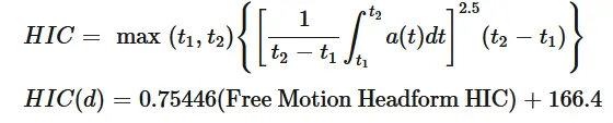
The average value of acceleration for the time interval between t1 = 2.5 ms and t2 = 15 ms is given by `[ 1 / (t1 - t2) * underset (t1) overset (t2) int a (t) dt ] =`64.7
Therefore `HIC = max (t1,t2){[64.7]^2.5 (15-2.5)} =`420.89
`HIC (d) = 0.75446 (420.892) + 166.4 =`483.94
This value is extremely close to the value of 483.8 obtained from LS Prepost and therefore it is acceptable and within the safe value of 650 given by the NCAP protocol.
Conclusion
Thus the model has been simulated for the different simulation cases and the HIC results have been analyzed for
1) Impact of Simple head model against rigid wall
2) Impact of child headform against rigid wall
3) Impact of child headform against hood (steel)
4) Impact of child headform against hood (aluminium)
The model files can be found under the link below
https://drive.google.com/drive/folders/189_Yt89AJ-iTXdI2Q2vvcxEFctl4xygV?usp=sharing