Week - 5 - Modelling Spotwelds
Objective:
To model spotwelds between the given surfaces using Beam and Solid elements and compare the results.
Spotwelds using beam elements
Step 1: Creating spotwelds in the model
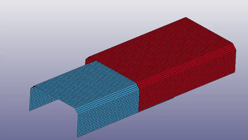
The model containing the upper and lower surfaces can be visualized in LS - Prepost as shown below.
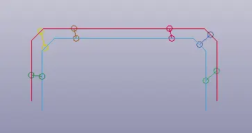
The spotwelds using beam elements are created at 6 locations between the upper and lower surfaces as shown below.
Step 2: Defining section and material
Beam
The beam is defined with MAT_100 card, which is a formulation meant for Spotwelds and the properties such as RHO, E and PR are given for steel. The unit system is g-mm-ms.
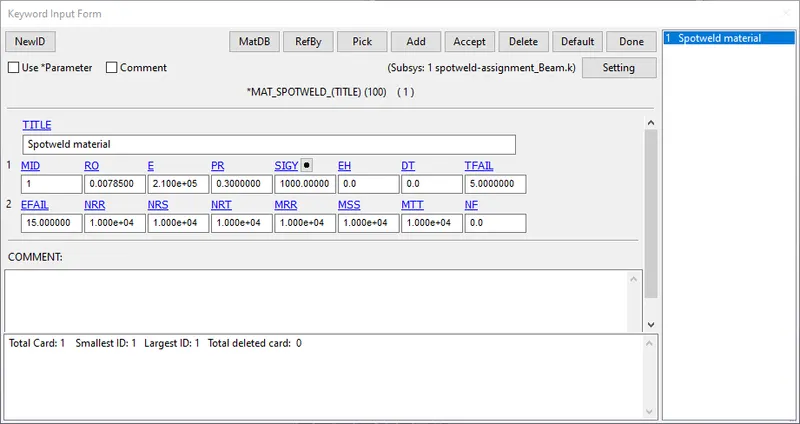
The time based failure criteria TFAIL is given as 5ms, since failure has to occur at half of the termination time of 10 ms. The other failure criteria are given very high values, in order to ensure that the spotwelds fail due to the time based failure criteria.
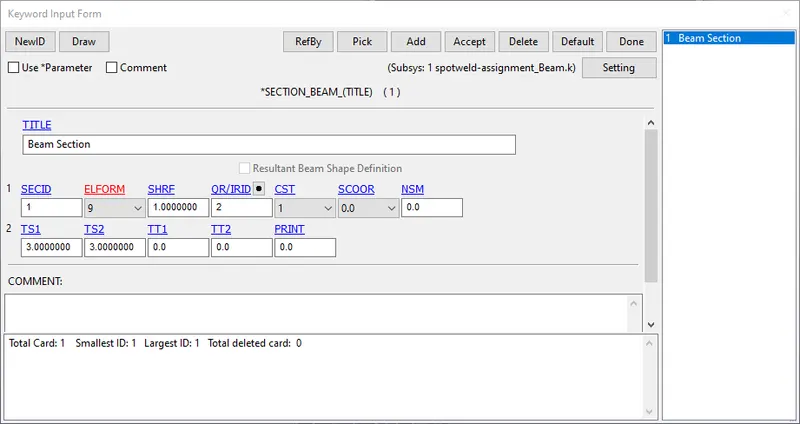
The beam is defined with a tubular cross section, with a thickness at both ends of 3 mm and ELFORM 9, since MAT_100 is applicable only for it.
Shell elements (Upper and lower surfaces)
The shell elements are defined using MAT_001 elastic card and the same values for E,RHO and PR as mentioned above.
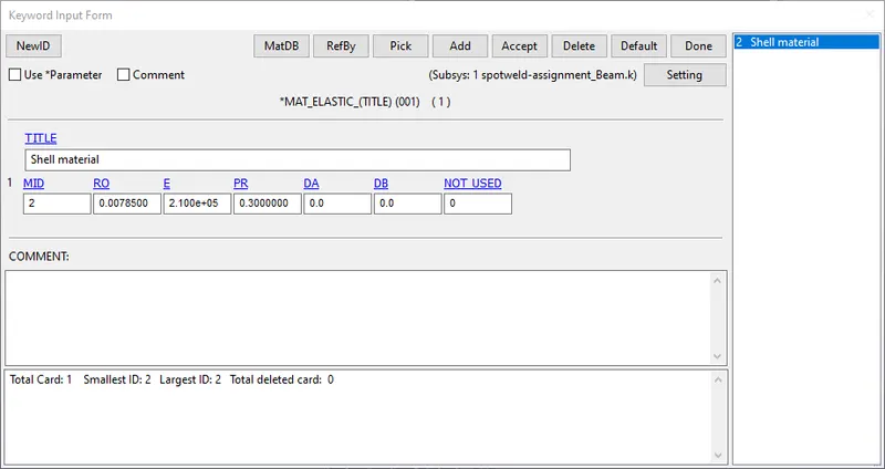
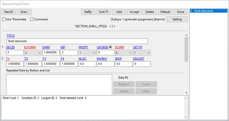
The shell elements are defined using a thickness of 1.5 mm and ELFORM 2.
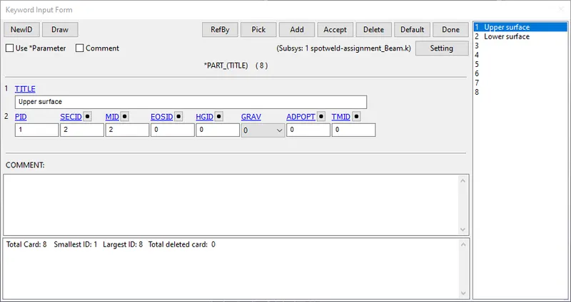
The section and the material are now assigned to the respective part IDs of the shell and the beam elements as shown below. Part IDs 3 to 8 refer to the beam elements.
Step 3: Defining contacts
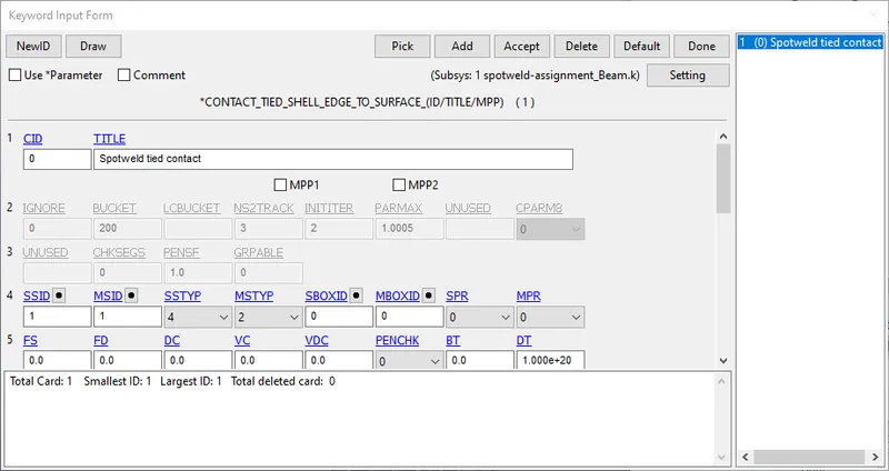
A tied shell edge to surface contact is defined between the upper and the lower surfaces and the nodes of the beam elements.
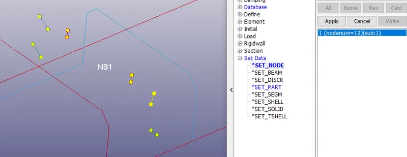
A part set is created with both the surfaces, and a nodeset with the 12 nodes of the beam elements, which are the master and the slave segments respectively for the contact.
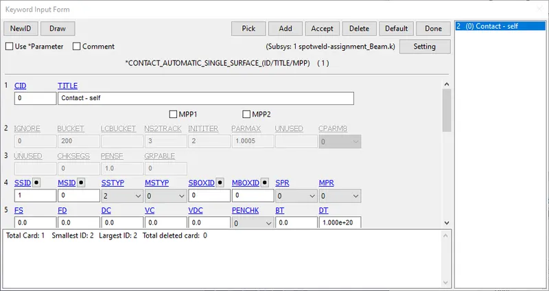
An automatic single surface contact is defined to represent the self contact between both the surfaces, so that they donot come into contact with each other, when the spotwelds fail. The part set containing both parts is the slave segment. A self contact in LS Dyna does not need the definition of a master segment.
Step 4: Boundary conditions, database and control cards
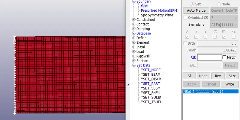
A nodeset with the end nodes of the upper surface are selected for SPC, with all six degrees of motion contrained.
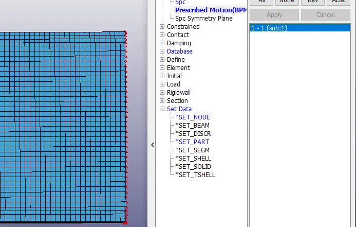
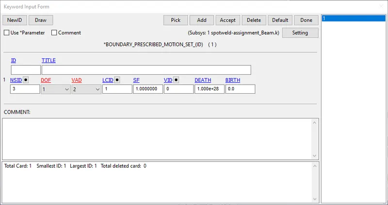
The nodes on the end of the lower surface are selected and a prescribed motion (displacement) is given to them.
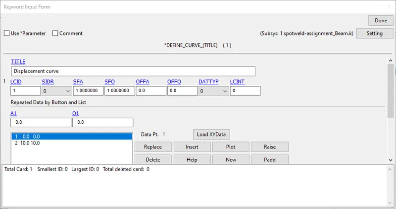
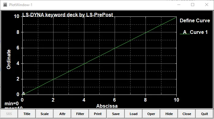
A curve specifying the displacement is defined as shown below.
Database cards
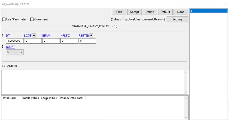
The binary D3 plot is defined with DT of 1 ms.
In the ASCII options, the GLSTAT, SWFORC and NODOUT are defined with DT of 1ms.
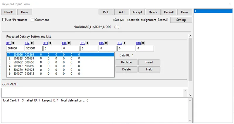
Since a NODOUT has been defined, the nodes for which output is generated need to be specified. A HISTORY_NODE is defined with all the nodes corresponding to the spotwelds.
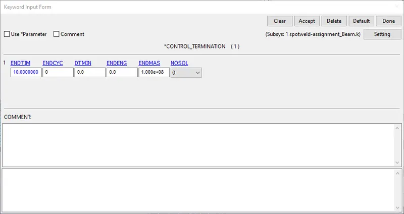
The CONTROL_TERMINATION card is defined with a time of 10 ms as specified above.
Spotwelds using solid elements
Step 1: Creating spotwelds in the model
The model containing the upper and lower surfaces can be visualized in LS - Prepost as shown below.
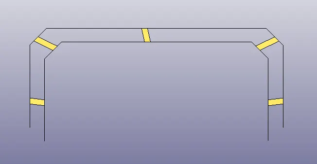
The spotwelds using solid elements are created at 5 locations between the upper and lower surfaces as shown below using the element edit option under element tools and having the element type as Hexa. The 8 nodes are selected from the upper and the lower surfaces.
Step 2: Defining section and material
Spotweld
The spotweld is defined with MAT_100 card, which is a formulation meant for Spotwelds and the properties such as RHO, E and PR are given for steel. The unit system is g-mm-ms.
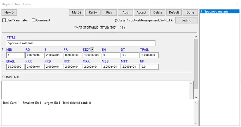
The time based failure criteria TFAIL is given as 5ms, since failure has to occur at half of the termination time of 10 ms. The other failure criteria are given very high values, in order to ensure that the spotwelds fail due to the time based failure criteria.
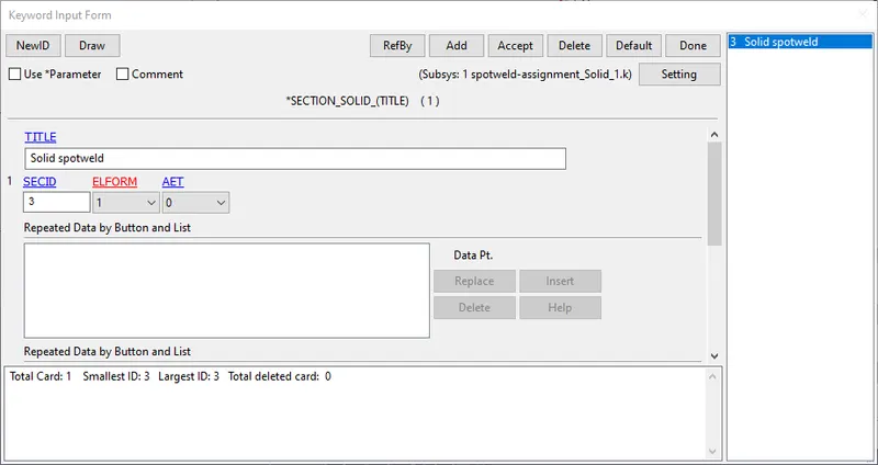
The solid spotwelds are defined with ELFORM 1, since MAT_100 is applicable only for it.
Shell elements (Upper and lower surfaces)
The shell elements are defined using MAT_001 elastic card and the same values for E,RHO and PR as mentioned above.
The shell elements are defined using a thickness of 1.5 mm and ELFORM 2.
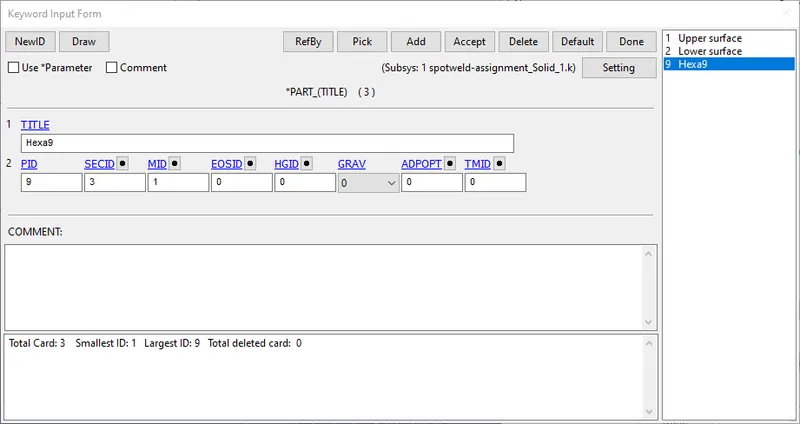
The section and the material are now assigned to the respective part IDs of the shell and the beam elements as shown below. Part ID 9 refers to the Hexa spotweld elements.
Step 3: Defining contacts
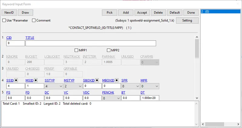
A contact spotweld is defined between the upper and the lower surfaces and the nodes of the beam elements.
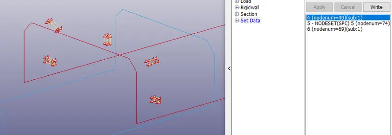
A part set is created with both the surfaces, and a nodeset with the 40 nodes of the solid spotweld elements, which are the master and the slave segments respectively for the contact.
An automatic single surface contact is defined to represent the self contact between both the surfaces, so that they donot come into contact with each other, when the spotwelds fail. The part set containing both parts is the slave segment. A self contact in LS Dyna does not need the definition of a master segment.
Step 4: Boundary conditions, database and control cards
A nodeset with the end nodes of the upper surface are selected for SPC, with all six degrees of motion contrained.
The nodes on the end of the lower surface are selected and a prescribed motion (displacement) is given to them.
A curve specifying the displacement is defined as shown below.
Database cards
The binary D3 plot is defined with DT of 1 ms.
In the ASCII options, the GLSTAT, SWFORC and NODOUT are defined with DT of 1ms.
Since a NODOUT has been defined, the nodes for which output is generated need to be specified. A HISTORY_NODE is defined with all the nodes corresponding to the spotwelds.
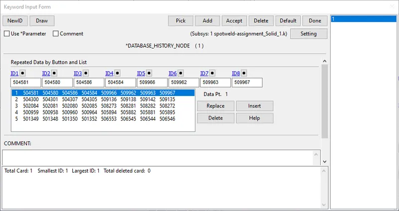
The CONTROL_TERMINATION card is defined with a time of 10 ms as specified above.
The models are saved separately and the simulation is done.
Results
Beam spotweld
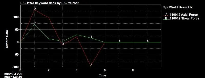
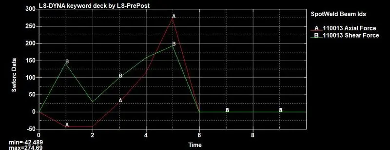
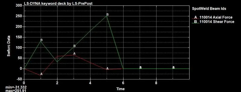
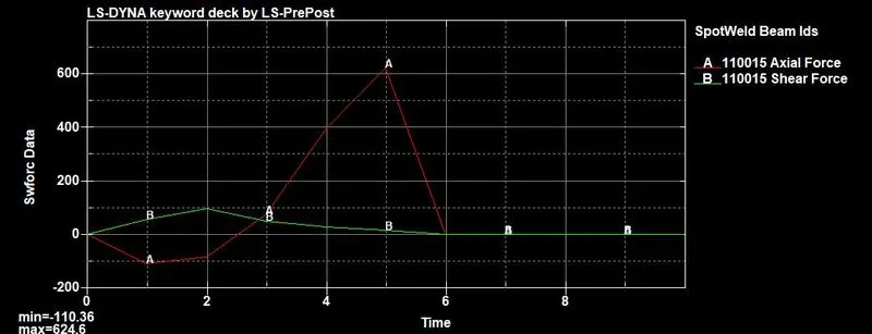
From the simulation run of the beam spotwelds, it can be seen that the spotwelds fail exactly at the TFAIL time of 5 ms.
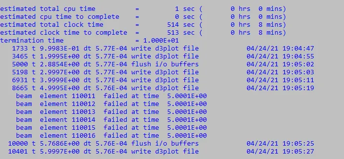
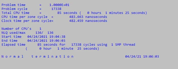
This can also be verified from the D3 plot, where the failure of each element can be plotted against time.

It can be seen, that the spotwelds start failing at exactly 5 ms.
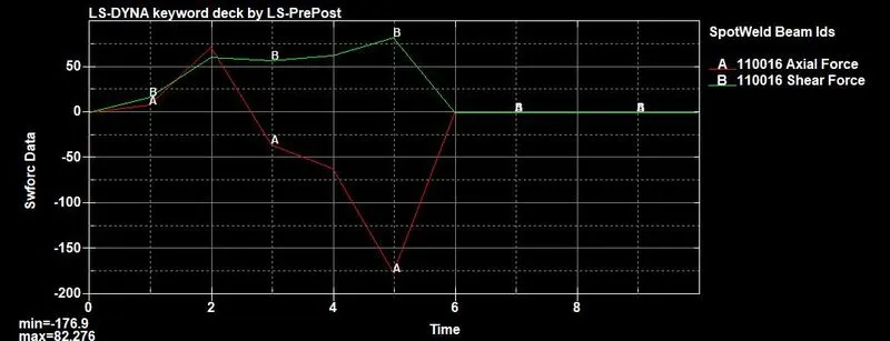
Axial and Shear forces
The axial and shear forces at each of the 6 spotwelds can be seen below.
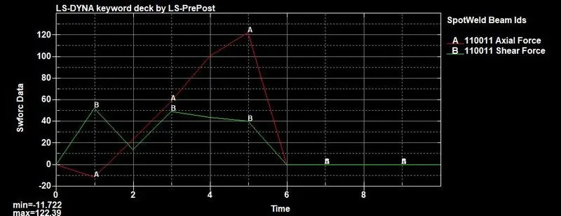
The displacements of the spotweld nodes on the upper and the lower surfaces can be seen from the NODOUT output as shown below.
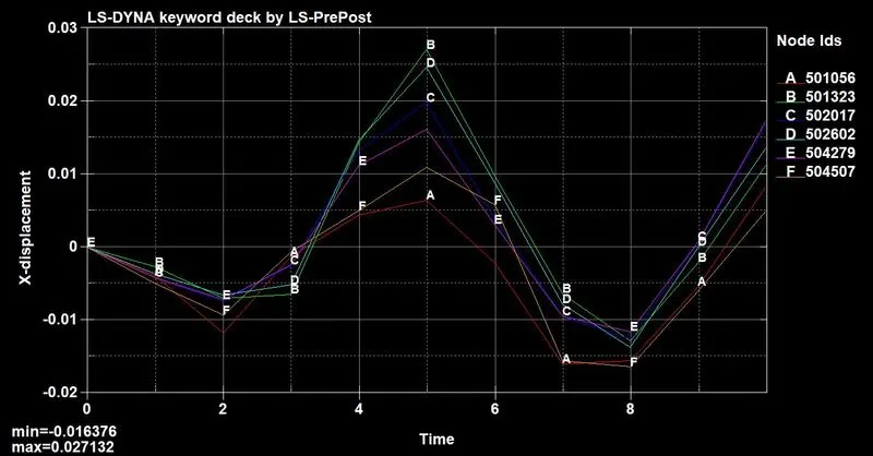
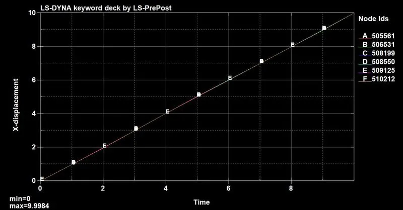
It can be seen that the nodes on the upper surfaces move as a result of the displacement applied to the lower surface, which is apparent from the above image showing the given displacement of 10 mm on all nodes on the lower surface.
Von mises stress
The von mises stress can be seen in the illustration below.

The maximum stress is 415 Gpa.
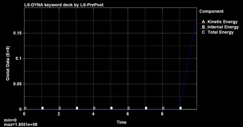
Energy plot
The internal, kinetic and total energies can be seen from the GLSTAT output as shown below.
Solid spotweld
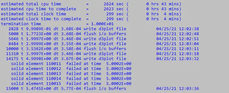
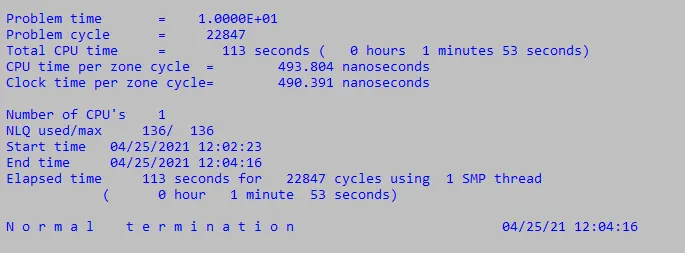
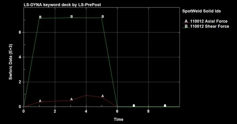
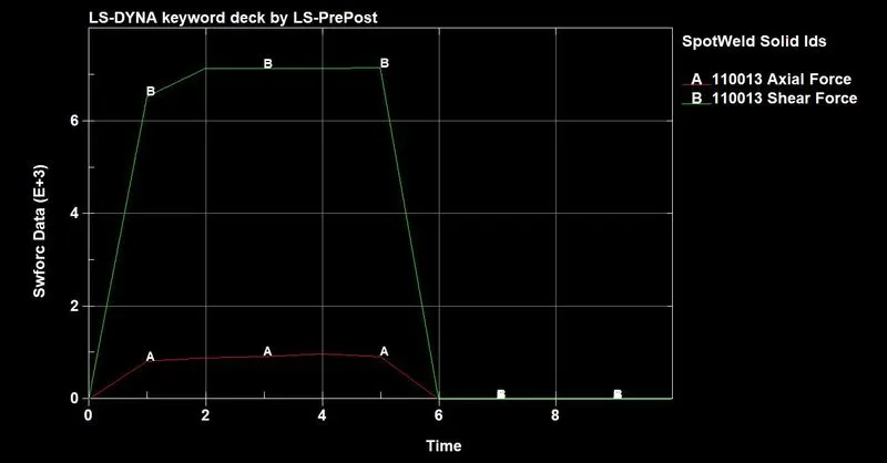
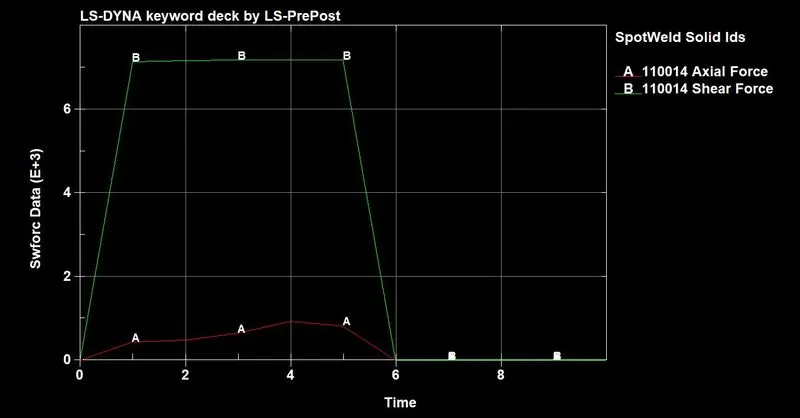
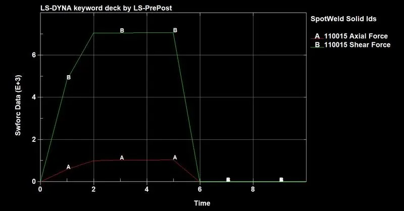
From the simulation run of the solid spotwelds, it can be seen that the spotwelds fail exactly at the TFAIL time of 5 ms.
This can also be verified from the D3 plot, where the failure of each element can be plotted against time.
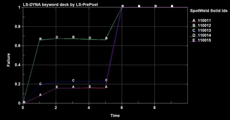
It can be seen, that the spotwelds start failing at exactly 5 ms.
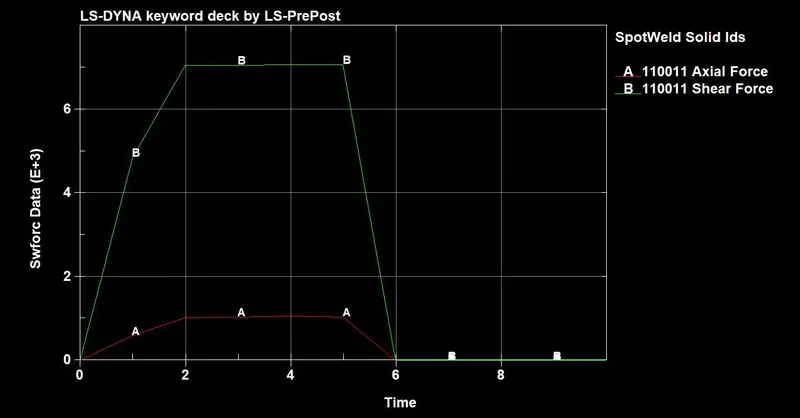
Axial and Shear forces
The axial and shear forces at each of the 5 spotwelds can be seen below.
The displacements of the spotweld nodes on the upper and the lower surfaces can be seen from the NODOUT output as shown below.
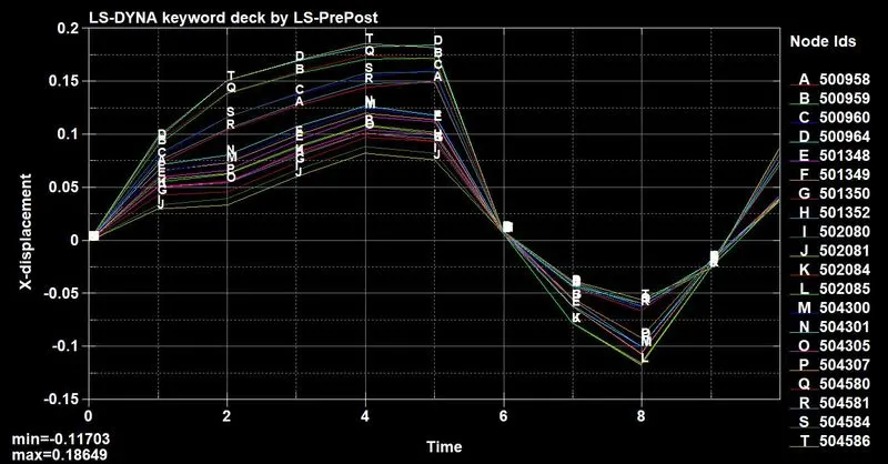
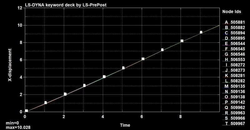
It can be seen that the nodes on the upper surfaces move as a result of the displacement applied to the lower surface, which is apparent from the above image showing the given displacement of 10 mm on all nodes on the lower surface.
Von mises stress
The von mises stress can be seen in the illustration below.
The maximum stress is 2498 Gpa.
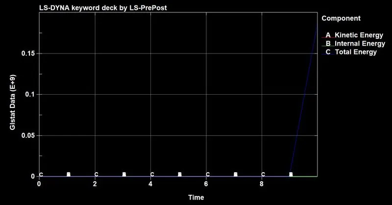
Energy plot
The internal, kinetic and total energies can be seen from the GLSTAT output as shown below.
Conclusion
The spotwelds using beam and solid elements have been simulated and the results have been analyzed and compared.
The relevant files are attached below.