Week 11 - Simulation of Flow through a pipe in OpenFoam
Objective
To calculate the flow variables anaytically and compare them with the numerical results and to study the velocity profile at various sections over the length of the pipe.
Solution
The flow of the fluid over the length of the pipe is assumed as laminar. The Reynolds number given is 2100.
The working fluid is water, with a density of 1000 kg m^-3.
Hagen Poiseuille's Equation
This is a physical aw that gives the pressure drop in an incompressible and Newtonian fluid in laminar flow through a long cylindrical pipe of constant cross section
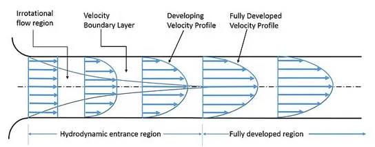
Length of entrance - The distance the fluid travels after entering the pipe before the complete development of the flow.
Hydrodynamic entrance region - Area of the pupe where the fluid entering the pipe develops a velocity profile due to the viscous forces, that are spreading from the interior walls of pipes.
Here, the fluid enters a pipe at a constant speed, hence fluid particles in the layer in contact with the pipe's surface come to a complete rest.
That layer, that is in contact with the pipe surface is resistant to the acceleration of the neighbouring layers due to the viscous forces produced within the fluid and gradually slows down the adjacent layers of the fluid, by forming a velocity profile.
For conservation of mass, the velocity of the layers of fluid at the centre of the pipe increases, in order to compensate the reduced velocities of the layer of fluid near the pipe surface.
This generates a velocity gradient across the cross section of the pipe.
Fully developed region - Here the velocity profile does not change in the fluid flow direction.
The flow variables are calculated as follows
Diameter = 0.004m
Density `rho = 1000 kg m^-3`
Kinematic viscosity of water `nu = 8.917 e-7 m^2 / s`
Dynamic viscosity of water `mu = rho*nu = 8.917 e-4 m^2 / s`
Reynolds number Re = 2100
Average velocity `V underset(avg)``= (mu * Re) / (rho*D)`
= 8.91e-4*2100/1000*0.004) = 0.4678m/s
Max velocity `V underset(max)`= 2*`V underset(avg)` = 0.936m/s
Entrance length Le = 0.05*Re*D
=0.05*2100*0.004 = 0.42m
Total length of pipe L = Le + 0.3
= 0.42 + 0.3 = 0.72m.
Pressure drop (`trianglep`) = `8*mu*L/r^2*Vunderset(avg)`
=8*8.91e-4*0.468*4.5/(0.002^2) = 600.17 Pa
Kinematic pressure `P = (triangleP)/rho` = 600.17/1000 = 0.6001 `m^2/s^2`
These calculations are done using a Matlab script and the blockMeshdict file for the simulation is also generated as follows
clear all
close all
clc

% Inputs
Re = 2100;      % Reynolds number
D = 0.004;       % Diameter of pipe
rho = 1000;     % density
nu = 8.91e-7;   % Kinematic viscosity

% Initial Calculations

mu = nu*rho; % Dynamic viscosity
V_avg = mu*Re/(rho*D);
V_max = 2*V_avg;

r = D/2;    % Radius in m

L_entr = 0.05*D*Re; % Length at entrance
L = L_entr + 0.3; % Total length

% Hagen Poiseuille calculations

delta_p = 8*mu*V_avg*L/r^2;     % Pressure
Kin_pressure = delta_p/rho;     % Kinematic Pressure

%Wedge angle
theta = 3;

R = linspace(0,r,1000);

for i = 1:length(R)
    tau(i) = 2*mu*V_max*(abs(R(i)))/r^2;
end

%Plot
plot(R,tau);
xlabel('Radius in m');
ylabel('Shear stress in N/m^2');
title('Variation of shear stress along radius');
grid on
hold on

%%
% BLOCKMESH DICT FILE

% Vertices
v0 = [0 0 0];
v1 = [0 r*cosd(theta/2) r*sind(theta/2)];
v2 = [0 r*cosd(theta/2) -r*sind(theta/2)];
v3 = [L 0 0];
v4 = [L r*cosd(theta/2) r*sind(theta/2)];
v5 = [L r*cosd(theta/2) -r*sind(theta/2)];


f1 = fopen('blockMeshDict.txt','w');


fprintf(f1,'convertToMeters 1;\n\n');

% Vertices
fprintf(f1,'Vertices\n');
fprintf(f1,'(\n');
fprintf(f1, '\t(%d, %d, %d)\n',0,0,0);
fprintf(f1, '\t(%d, %d, %d)\n',0, r*cosd(theta/2), -r*sind(theta/2));
fprintf(f1, '\t(%d, %d, %d)\n',0, r*cosd(theta/2), r*sind(theta/2));
fprintf(f1, '\t(%d, %d, %d)\n',L,0,0);
fprintf(f1, '\t(%d, %d, %d)\n',L, r*cosd(theta/2), -r*sind(theta/2));
fprintf(f1, '\t(%d, %d, %d)\n',L, r*cosd(theta/2), r*sind(theta/2));
fprintf(f1,')\n\n');


% Blocks
fprintf(f1, '\n');
fprintf(f1,'blocks\n');
fprintf(f1,'(\n');
fprintf(f1, '\t hex (0 3 4 1 0 3 5 2) ( %d %d %d) simpleGrading(1 0.1 1)\n',300,30,1);
fprintf(f1,')\n');

% Edges
 fprintf(f1,'edges\n(\n\t arc %d %d (%d %d %d)\n', 1,2,0,r,0);
 fprintf(f1,'\t arc %d %d (%d %d %d)\n', 4,5,L,r,0);
 fprintf(f1,');\n\n');

% Boundary
fprintf(f1,'boundary\n(\n');
fprintf(f1,'\t inlet\n');
fprintf(f1,'\t {\n');
fprintf(f1,'\t\t type patch;\n');
fprintf(f1,'\t\t faces\n');
fprintf(f1,'\t\t(\n');
fprintf(f1,'\t\t\t(0 1 2 0)\n');
fprintf(f1,'\t\t );\n');

fprintf(f1,'\t outlet\n');
fprintf(f1,'\t {\n');
fprintf(f1,'\t\t type patch;\n');
fprintf(f1,'\t\t faces\n');
fprintf(f1,'\t\t(\n');
fprintf(f1,'\t\t\t(3 5 4 3)\n');
fprintf(f1,'\t\t );\n');
fprintf(f1,'\t}\n');

fprintf(f1,'\t top\n');
fprintf(f1,'\t {\n');
fprintf(f1,'\t\t type wall;\n');
fprintf(f1,'\t\t faces\n');
fprintf(f1,'\t\t(\n');
fprintf(f1,'\t\t\t(1 4 5 2)\n');
fprintf(f1,'\t\t );\n');
fprintf(f1,'\t }\n');

fprintf(f1,'\t back\n');
fprintf(f1,'\t {\n');
fprintf(f1,'\t\t type wedge;\n');
fprintf(f1,'\t\t faces\n');
fprintf(f1,'\t\t(\n');
fprintf(f1,'\t\t\t(0 2 5 3)\n');
fprintf(f1,'\t\t );\n');
fprintf(f1,'\t }\n');

fprintf(f1,'\t front\n');
fprintf(f1,'\t {\n');
fprintf(f1,'\t\t type wedge;\n');
fprintf(f1,'\t\t faces\n');
fprintf(f1,'\t\t(\n');
fprintf(f1,'\t\t\t(0 3 4 1)\n');
fprintf(f1,'\t\t );\n');
fprintf(f1,'\t }\n');

fprintf(f1,'\t axis\n');
fprintf(f1,'\t {\n');
fprintf(f1,'\t\t type empty;\n');
fprintf(f1,'\t\t faces\n');
fprintf(f1,'\t\t(\n');
fprintf(f1,'\t\t\t(0 3 3 0)\n');
fprintf(f1,'\t\t );\n');
fprintf(f1,'\t }\n');
fprintf(f1,'mergePatchPairs\n(\n');
fprintf(f1,');\n');

fclose(f1);
BlockMeshDict file
/*--------------------------------*- C++ -*----------------------------------*\
  =========                 |
  \\      /  F ield         | OpenFOAM: The Open Source CFD Toolbox
   \\    /   O peration     | Website:  https://openfoam.org
    \\  /    A nd           | Version:  9
     \\/     M anipulation  |
\*---------------------------------------------------------------------------*/
FoamFile
{
    format      ascii;
    class       dictionary;
    object      blockMeshDict;
}
// * * * * * * * * * * * * * * * * * * * * * * * * * * * * * * * * * * * * * //

convertToMeters 1;

vertices
(
    (0 0 0)
    (0 0.002 -5.2354e-5)
    (0 0.002 5.2354e-5)
    (0.72 0 0)
    (0.72 0.002 -5.2354e-5)
    (0.72 0.002 5.2354e-5)

);

blocks
(
    hex (0 3 4 1 0 3 5 2) (500 50 1) simpleGrading (1 0.1 1)
);

edges
(

);

boundary
(
    inlet
    {
        type patch;
        faces
        (
            (0 1 2 0)
        );
    }
    outlet
    {
        type patch;
        faces
        (
            (3 5 4 3)

        );
    }
    top
    {
        type wall;
        faces
        (
            (1 4 5 2)

        );
    }
    front
    {
        type wedge;
        faces
        (
            (0 3 4 1)

        );
    }
    back
    {
        type wedge;
        faces
        (
            (0 2 5 3)

        );
    }
    axis
    {
        type empty;
        faces
        (
            (0 3 3 0)

        );
    }
);

mergePatchPairs
(
);

//************************************************************************* //
controlDict
/*--------------------------------*- C++ -*----------------------------------*\
  =========                 |
  \\      /  F ield         | OpenFOAM: The Open Source CFD Toolbox
   \\    /   O peration     | Website:  https://openfoam.org
    \\  /    A nd           | Version:  9
     \\/     M anipulation  |
\*---------------------------------------------------------------------------*/
FoamFile
{
    format      ascii;
    class       dictionary;
    location    "system";
    object      controlDict;
}
// * * * * * * * * * * * * * * * * * * * * * * * * * * * * * * * * * * * * * //

application     icoFoam;

startFrom       startTime;

startTime       0;

stopAt          endTime;

endTime         8;

deltaT          0.001;

writeControl    timeStep;

writeInterval   20;

purgeWrite      0;

writeFormat     ascii;

writePrecision  6;

writeCompression off;

timeFormat      general;

timePrecision   6;

runTimeModifiable true;


// ************************************************************************* //
Pressure file
/*--------------------------------*- C++ -*----------------------------------*\
  =========                 |
  \\      /  F ield         | OpenFOAM: The Open Source CFD Toolbox
   \\    /   O peration     | Website:  https://openfoam.org
    \\  /    A nd           | Version:  9
     \\/     M anipulation  |
\*---------------------------------------------------------------------------*/
FoamFile
{
    format      ascii;
    class       volScalarField;
    object      p;
}
// * * * * * * * * * * * * * * * * * * * * * * * * * * * * * * * * * * * * * //

dimensions      [0 2 -2 0 0 0 0];

internalField   uniform 0;

boundaryField
{
    inlet
    {
        type            zeroGradient;
    }

    outlet
    {
        type            fixedValue;
        value		 uniform 0;
    }

    back
    {
        type            wedge;
    }
    front
    {
        type            wedge;
    }
    top
    {
        type            zeroGradient;
    }
}

// ************************************************************************* //
Velocity file
/*--------------------------------*- C++ -*----------------------------------*\
  =========                 |
  \\      /  F ield         | OpenFOAM: The Open Source CFD Toolbox
   \\    /   O peration     | Website:  https://openfoam.org
    \\  /    A nd           | Version:  9
     \\/     M anipulation  |
\*---------------------------------------------------------------------------*/
FoamFile
{
    format      ascii;
    class       volVectorField;
    object      U;
}
// * * * * * * * * * * * * * * * * * * * * * * * * * * * * * * * * * * * * * //

dimensions      [0 1 -1 0 0 0 0];

internalField   uniform (0.4678 0 0);

boundaryField
{
    inlet
    {
        type            fixedValue;
        value		 uniform (0.4678 0 0);
    }

    outlet
    {
        type            zeroGradient;

    }

    back
    {
        type            wedge;
    }
    front
    {
        type            wedge;
    }
    top
    {
        type            noSlip;
    }
}

// ************************************************************************* //
Results
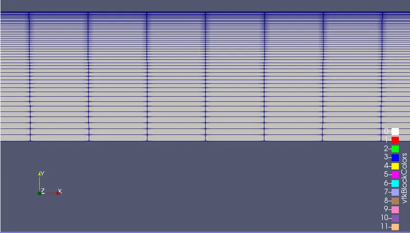
Generated mesh with Grading
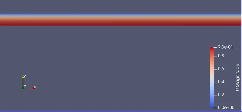
Velocity
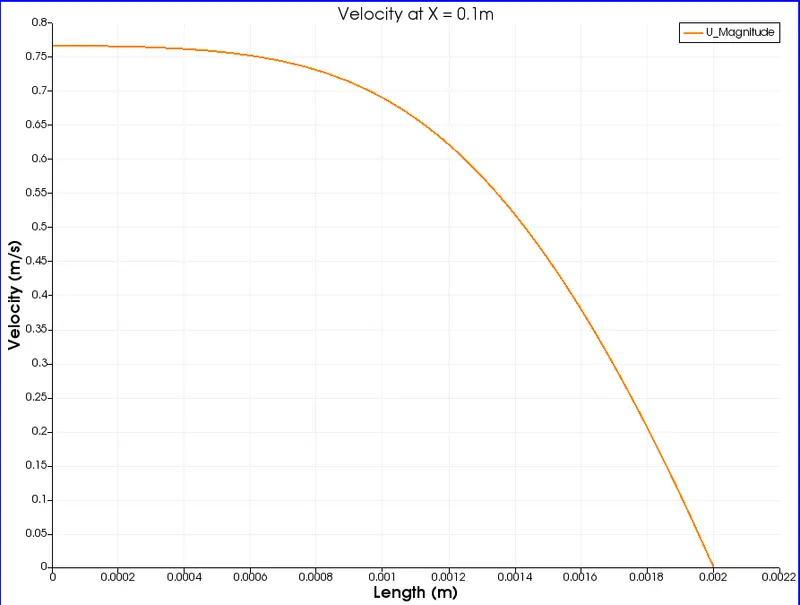
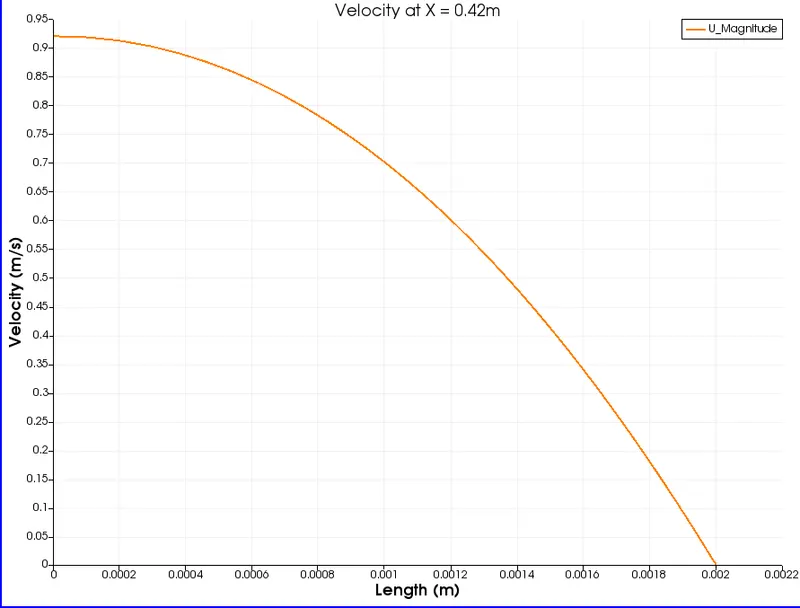
The velocity is zero at the wall of the pipe, where the boundary layer exists. It becomes maximum towards the centre of the pipe.
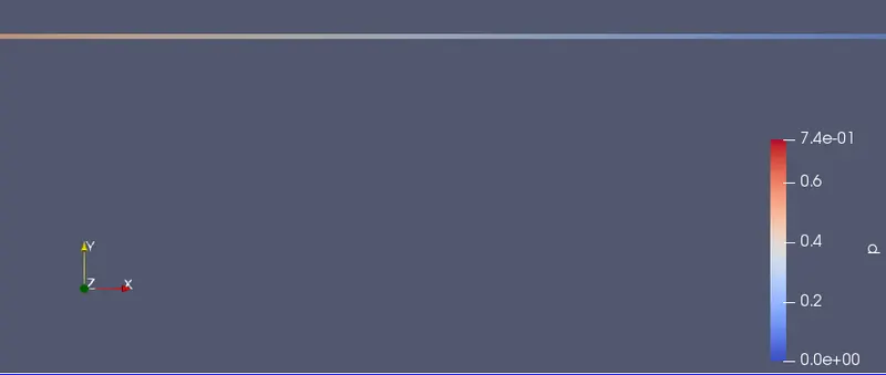
Pressure
The high pressure is visible on the left side and the low pressure on the right. The fluid flows from a region of high pressure to a region of low pressure.
Velocity profiles
X = 0.1 m
X = 0.42 m
X = 0.72m
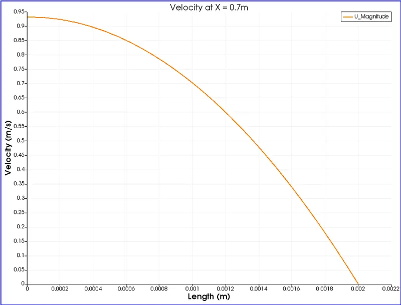
Observation
As we move along the length of the pipe, the velocity profile changes from a steep decline at the initial section to a parabolic curve at the entrance length (0.42m) and stays parabolic through the length of the pipe (0.72m).
Shear stress
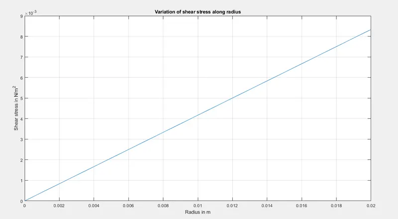
When the fluid is moving, shear stresses are developed as the particles in the flow move relative to each other. For a fluid flowing in the pipe, the fluid velocity near the wall remains zero. Shear force is generated because of the friction between the adjacent layers of fluid that move relative to each other.
If the value of viscosity is constant, the shear stress is linearly dependent on the velocity gradient. As the change in velocity is larger, more the shear stress near the walls.