Assignment 2-RADIOSS Engine File Editing & 3D Meshing Challenge
Objectives:
1. To calculate the speed of sound through steel and the critical timestep for the given length.
2. To edit the radioss engine file with the critical timestep and the frequency at which output plots are generated, for 20 steps.
3. To 3D mesh the housing assembly in Hypermesh using a tetramesh with a target element size of 5 mm and tet collapse of 0.15.
4. To 3D mesh the arm-bracket assembly in Hypermesh using a hex mesh and a target element size of 10mm.
1. Speed of sound through steel and critical timestep (Dt)
From the radioss starter out file FIRST_RUN_0000.rad, the initial information about the material properties and the unit system followed can be determined.
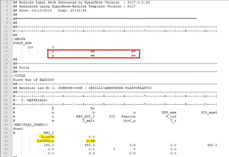
Here the material used is steel and the unit system is g-mm-ms.
The material properties in the above unit system are:
Density (Rho) = 0.0078 g/mm^3
Young's modulus (E) = 210*10^3 g/(mm.ms^2)
Poisson's ratio = 0.29.
Speed of sound can be calculated using the relation `c = sqrt(E/(rho)`
On substitution of the above values we obtain c as 5188.74 mm/ms.
Critical timestep `triangletc` = `(lc)/ c`
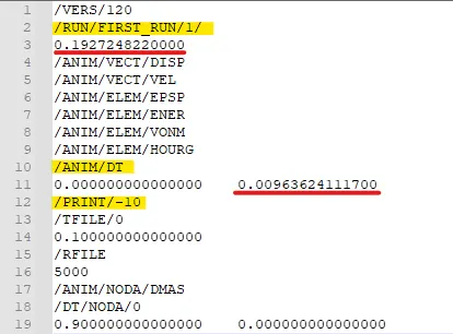
Using the length of 1000mm, the `triangletc` is 0.1927 ms.
The time interval at which plots should be written for 20 steps = 0.1927/20 = 0.009636 ms.
2. Radioss engine out file editing
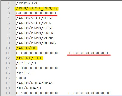
The radioss file FIRST_RUN_0001.rad contains the information about the critical timestep and the time interval at which output plots are written, as shown in the figure below.
The values of the timestep and the frequency are changed as shown below.
3. 3D Mesh - Cover Housing - Tetramesh
The housing assembly has two components - Cover and Hub as can be seen in the image below.
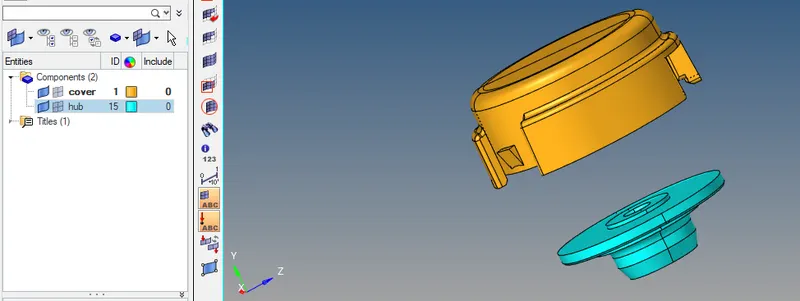
Both the components have to be meshed separately using a volume tetramesh
Cover
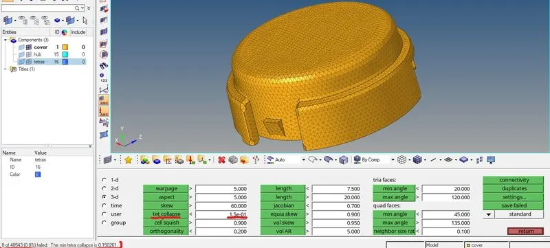
The cover is meshed using a volume tetramesh with an element size of 5mm and tet collapse is set to 0.15.
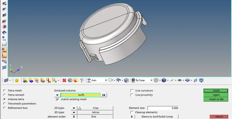
The mesh is created and checked for quality using the tet collapse criteria. There are no failed elements, as all the elements in the created mesh are above the required tet collapse value.
Hub
The hub is meshed using a volume tetramesh with an element size of 5mm and tet collapse is set to 0.15.
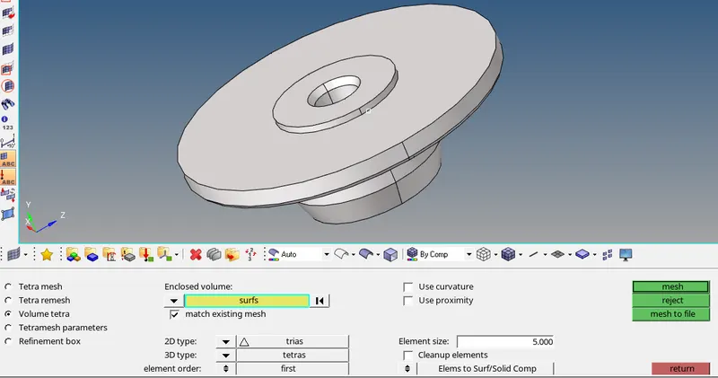
The mesh is created and checked for quality using the tet collapse criteria. There are no failed elements, as all the elements in the created mesh are above the required tet collapse value.
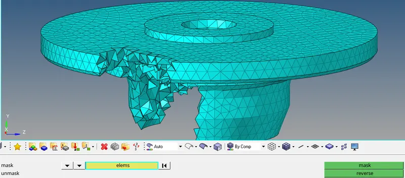
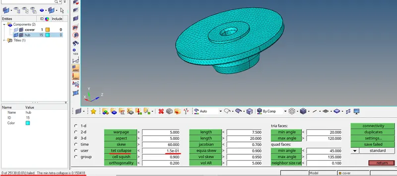
After both components in the assembly are meshed, they can be checked for connectivity and duplicates as shown below.
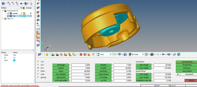
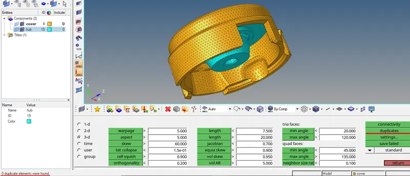
Thus the components of the housing assembly have been meshed successfully using a Tetramesh.
Number of failed elements (Tet collapse 0.15) - 0
Number of elements with connectivity issues - 0
Number of duplicate elements - 0
4. Arm - Bracket - Hex mesh
The arm - bracket assembly has four components as shown below.
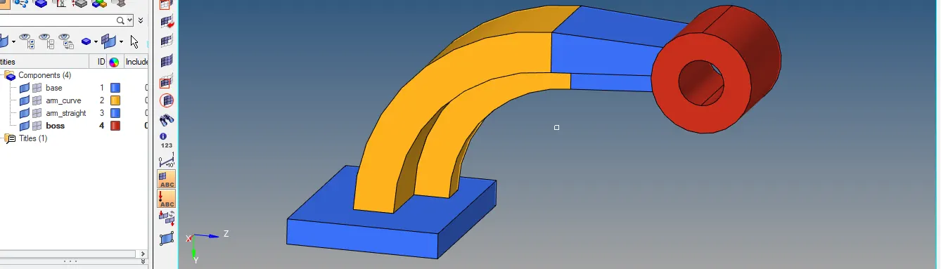
1. Base
2. Arm curve
3. Arm Straight
4. Boss
Each of these components has to be meshed separately using a different meshing method as described below.
1. Base
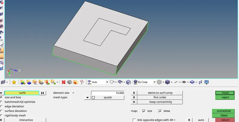
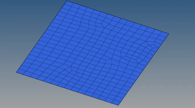
The top surface of the base is first meshed with 2D shell elements of quad type with an element size of 10mm as shown below.
The next step is to create a hex mesh on the base using the 3D - element offset command.
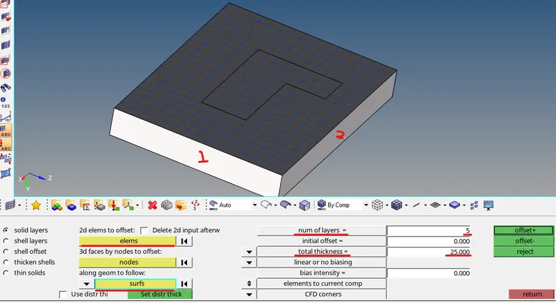
The 2D elements on the top surface are selected and the number of layers and total thickness of the component are specified as shown below.
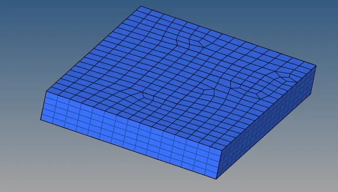
The final hex mesh on the base is shown in the figure below.
2. Arm curve
The arm curve is connected to the base as shown in the figure below.
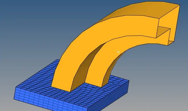
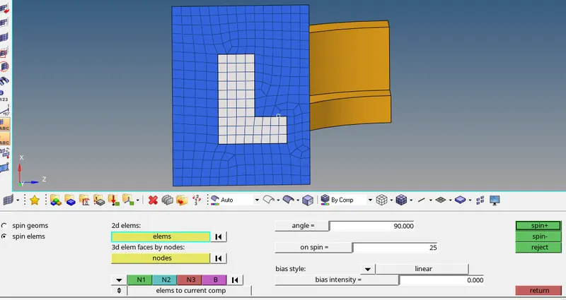
The central 2D elements on the top surface of the base are selected as the elements needed to mesh the arm curve using the 3D - Spin command as shown below.
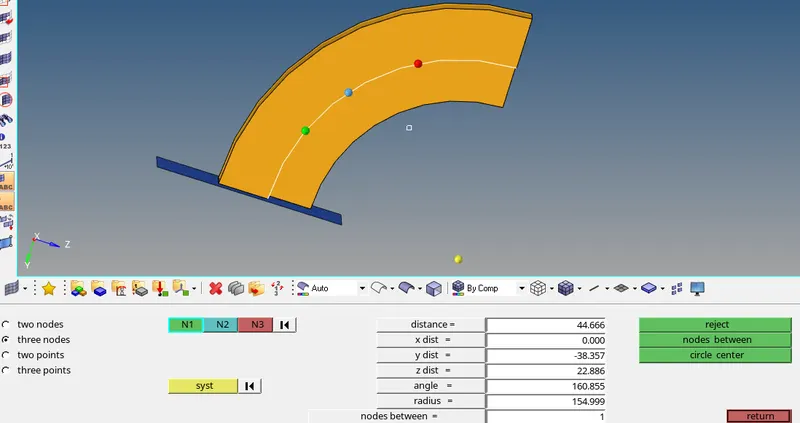
In order to spin the elements, a base node is needed, which can be created using the circle center option using three nodes in the distance menu.
Now the central node can be used as the base node for creating the 3D mesh as shown below.
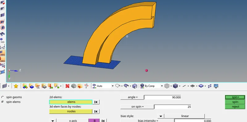
The final mesh is shown in the image below.
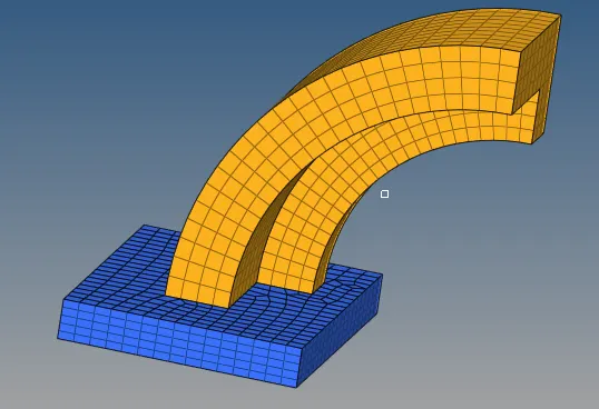
3. Arm Straight
The next section is a tapered section attached to the arm-curve on one end and the boss on the other end.
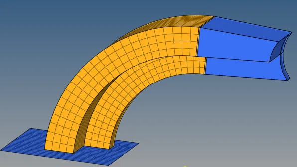
Therefore, this section can be meshed using the 3D- Linear solids option. This needs source and destination elements on the faces on either sides. Therefore 2D elements need to be created on either end face of the arm-straight.
The 2D elements on the arm-curve (LHS of the arm-straight) can be created using the find faces option as shown below.
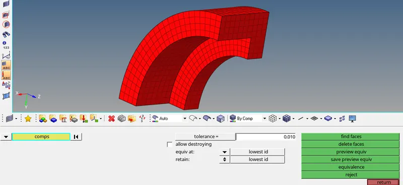
On the other side (RHS of the arm-straight), 2D elements can be created using the Automesh function.
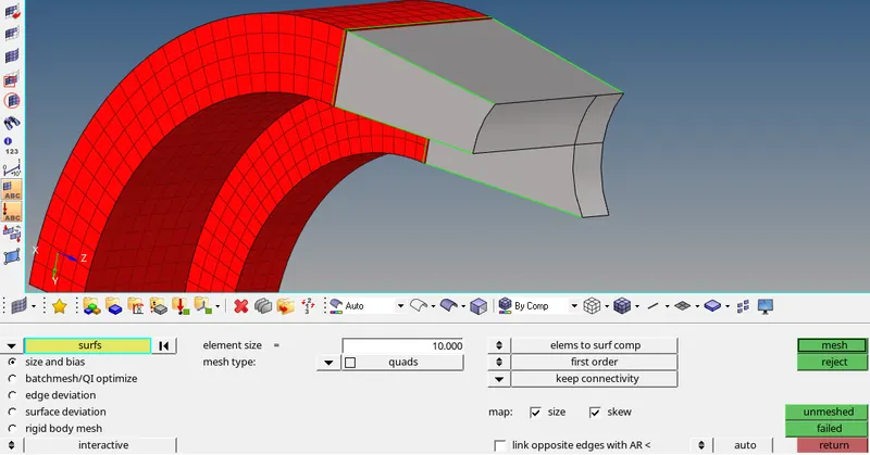
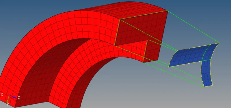
After ensuring that the number of elements on both end faces are equal, the 3D mesh can be created using the linear solids menu as shown below.
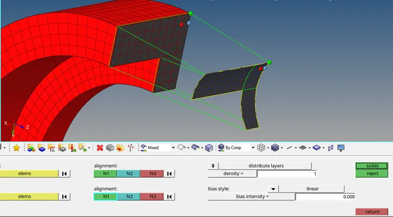
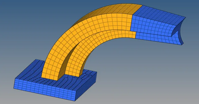
The density is given as 12 and the alignment nodes at both ends are chosen in the same order to ensure proper mesh generation.
The final mesh is shown in the image below.
4. Boss
The final part of the assembly is the boss which can be meshed using the 3D - line drag option.
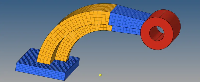
A 2D mesh is first created on the top surface of the boss using Automesh command and the same element size.
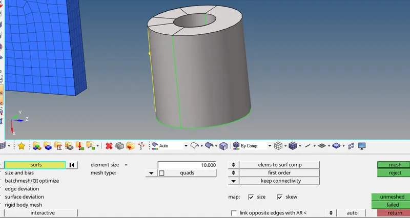
Using the above created mesh, a 3D mesh is created using the line drag option using source as none and target geom as the opposite face along the nodes on the cylindrical face.
The final mesh is shown in the image below.
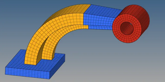
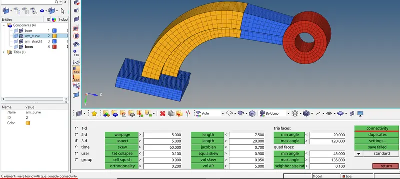
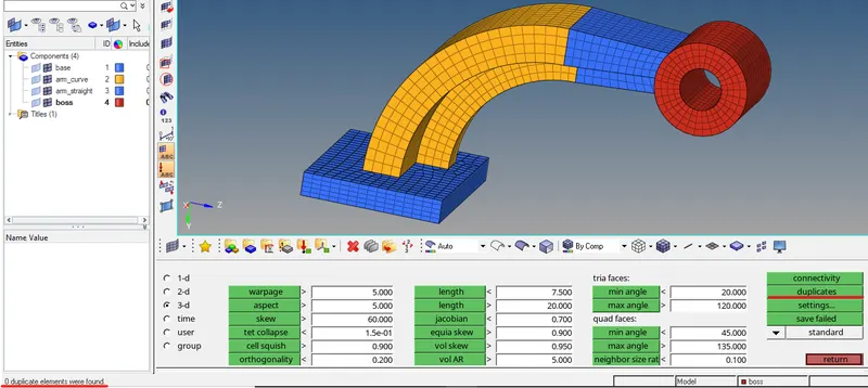
Finally the mesh can be checked for connectivity and duplicates to ensure mesh quality.
Thus the components of the arm-bracket assembly have been meshed successfully using a Hexmesh.
Number of elements with connectivity issues - 0
Number of duplicate elements - 0.
Conclusion
The four objectives have been met and the relevant model and engine files have been attached below.