Week - 4 - Crash Box Simulation
Objective:
To simulate the impact of the crash box against a rigid wall with two different thickness - 1.2mm and 1.5 mm.
1) Thickness 1.2 mm
Step 1: Setting up the Simulation
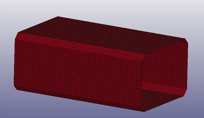
The .K file containing the crash box is imported into LS dyna as shown below.
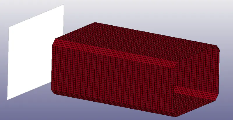
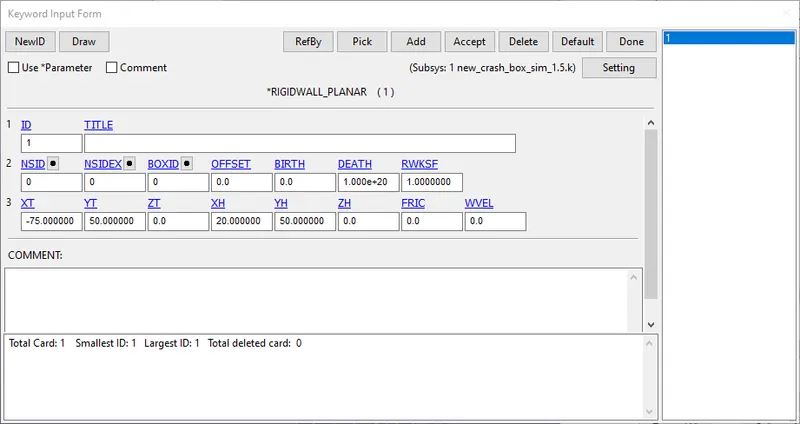
A planar rigid wall is created using the RIGIDWALL keyword and positioned using the appropriate X,Y and Z co-ordinates.
Step 2: Material and Section definition
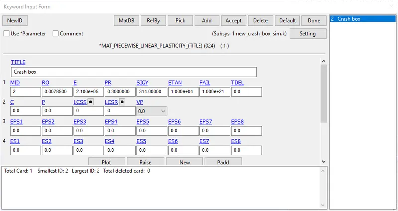
The crash box is defined with a steel material with the values given below using the MAT_24 card, since the plastic region also needs to be considered.
The shell section with a thickness of 1.2 mm is created as shown below.
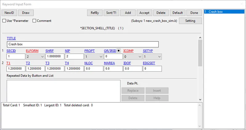
Both the section and the material are assigned to the part ID of the crash box.
Step 3: Contact and cross sectional area
A single surface contact is defined with the elements of the crash box as slave elements. A self contact in LS Dyna does not require a master segment definition.
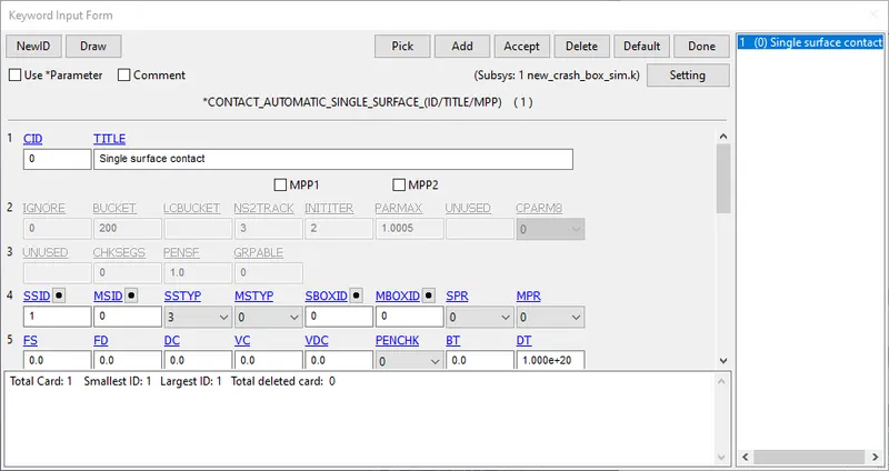
A cross sectional area is created in the middle of the crash box with nodes and attached elements on either side as shown below.

Acceleration is defined for a node at the centre of the crash box, which can be viewed in the ASCII output under NODOUT.
Step 4: Initial velocity
An initial velocity of 15 mm/ms is applied to the crash box in the negative X direction, which corresponds to a speed of 54 km/hr.
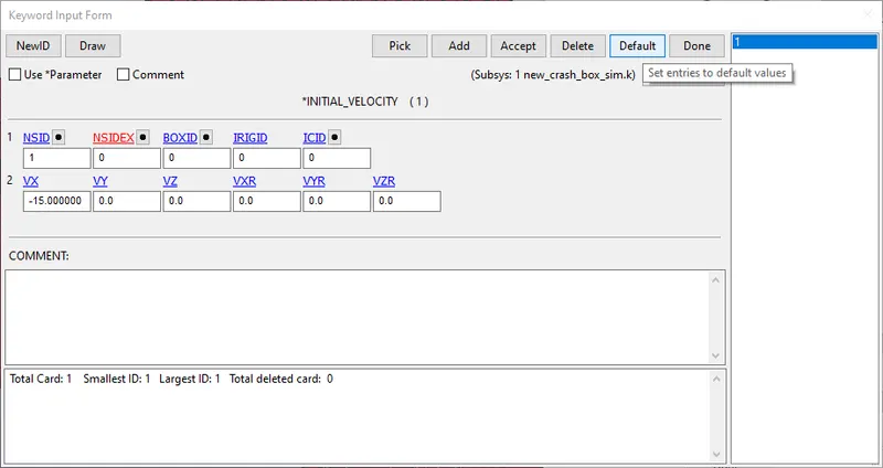
The model is ready for simulation and the runtime is defined as 8 ms, based on the distance between the crash box and the rigid wall of 75 mm and a speed of 15 mm/ms, which means that the impact would happen at 5 ms, which is approximately 50 steps. An extra 3 ms runtime is added in order to visualize the rebound of the crash box after impact.
2. Thickness 1.5 mm
The section thickness is now changed to 1.5 mm as shown below, with the rest of the steps being the same.
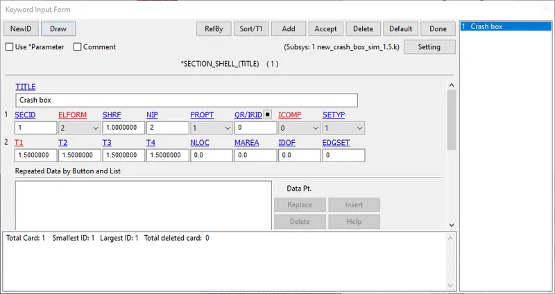
Results
The model is simulated and the results can be analyzed.
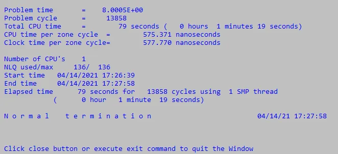
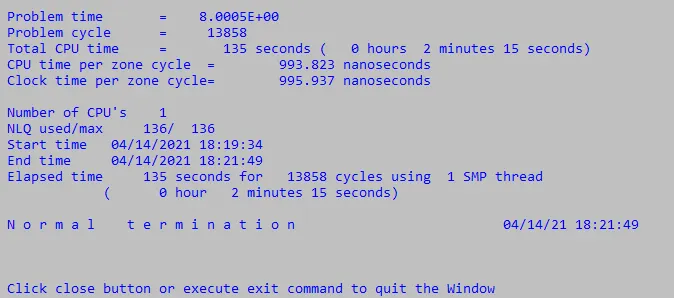
Runtime Thickness 1.2 mm vs 1.5 mm
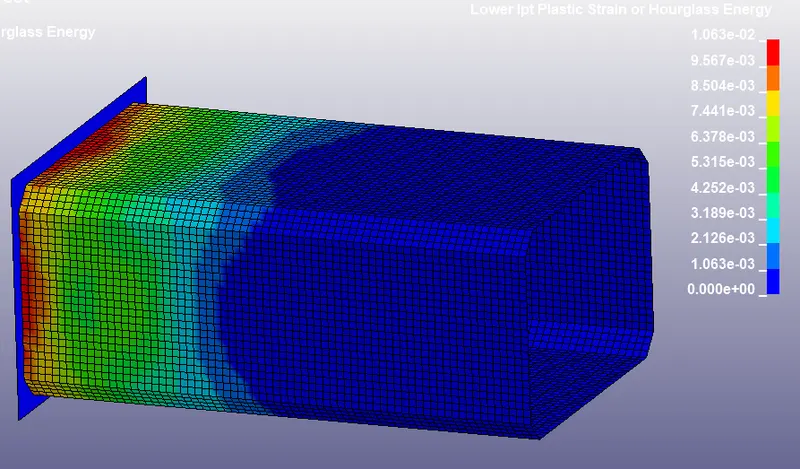
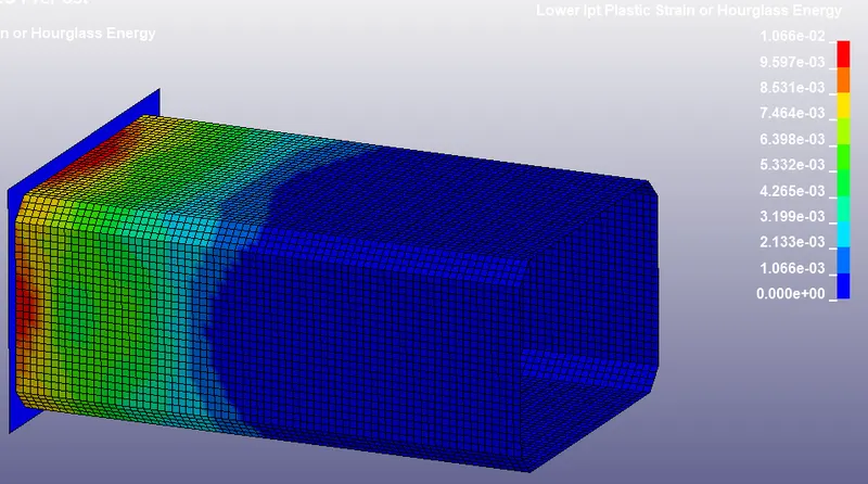
Von mises stress and strain - 1.2 mm vs 1.5 mm
The plots of von mises stress and strain can be visualized below.
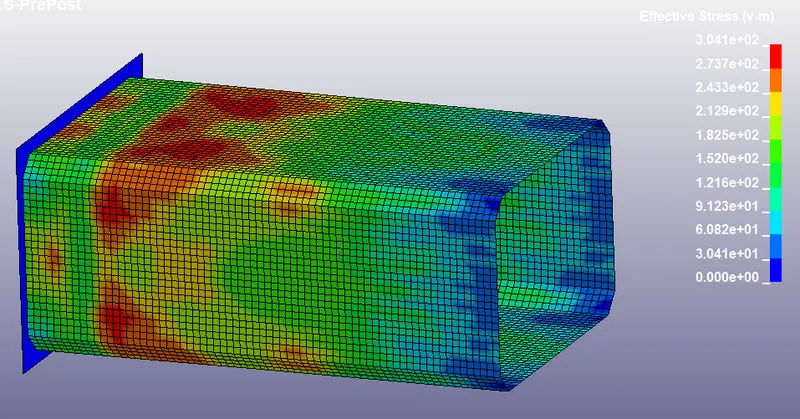
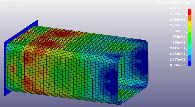
It can be seen that the stress value is slightly higher for the 1.5 mm thick crash tube compared to that of 1.2 mm.
Energy plot comparison - 1.2 mm vs 1.5 mm
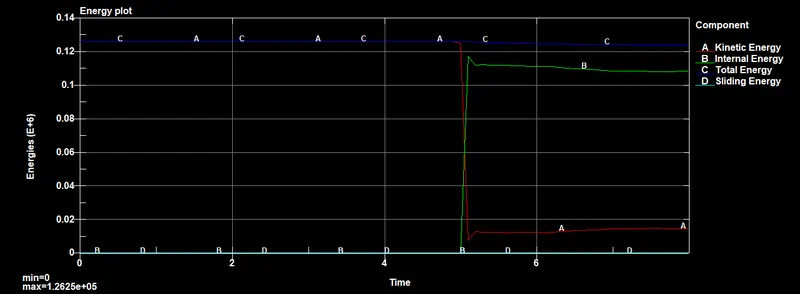
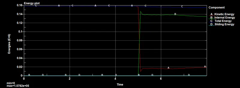
The maximum energy of the 1.5 mm case is 1.57e+5, which is slightly higher than the maximum energy of the 1.2 mm case of 1.26 e+5.
Cross sectional force comparison - 1.2 mm vs 1.5 mm
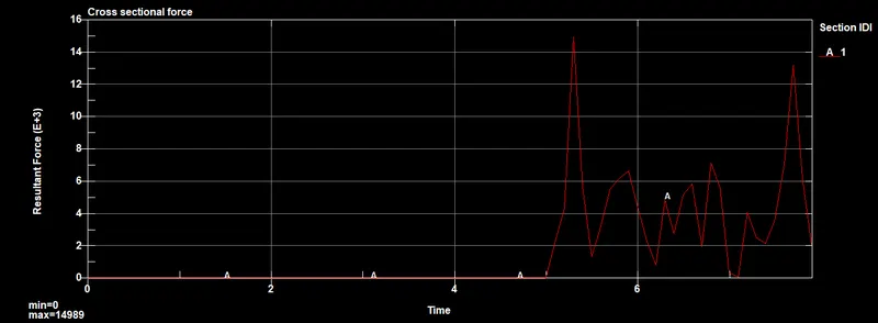
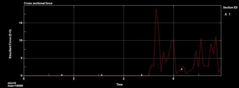
The resultant force in the 1.5 mm thickness case is 19099 N, which is slightly higher than the force in the 1.2mm case which is 14989 N.
Acceleration comparison - 1.2 mm vs 1.5 mm
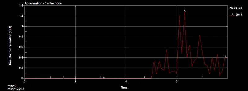
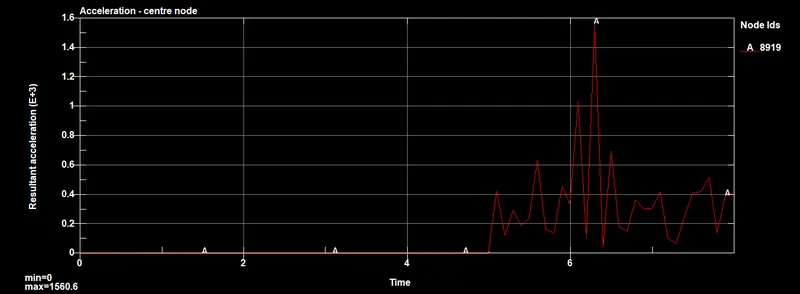
The centre node in the 1.5 mm case has a greater acceleration of 1560.6 mm/ms^2, compared to 1284.7 mm/ms^2 in the 1.2 mm case.
Conclusion
The impact of the crash box against a rigid wall has been simulated for two different crash box thicknesses - 1.2 mm and 1.5 mm, and the results have been compared.
The animations of both output files have been added in the google drive under the link below due to size constraints.
https://drive.google.com/drive/folders/1sBX4bW5Nh7IG6S1J9WIGhvSOI6AWgA4B?usp=sharing