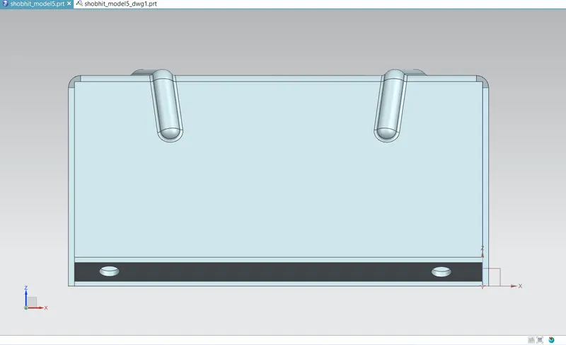
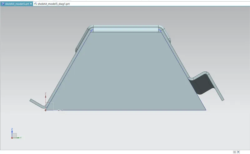
Advanced Sheet Metal Design Using NX Cad Challenge_5_Odd Shaped Enclosure
TITLE OF THE PROJECT: Advanced Sheet Metal Design Using NX Cad Challenge 5 Odd Shaped Enclosure
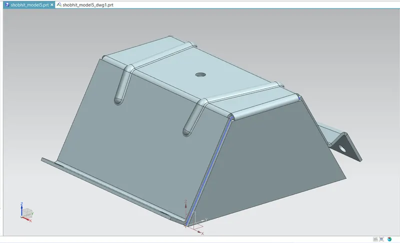
OBJECTIVE: To design an Odd shaped enclosure around a solid part model having the same odd shape by using a command named "Sheet Metal From Solid".
INTRODUCTION:
Sheet Metal is basically a sheet made out of metal like steel through a forming process called rolling and the thickness of sheetmetal starts from 0.5mm and goes upto 6mm. Sheet metal is one of major input material used in automotive manufacturing industries and several other industries. These sheets are transformed into useful products like BiW frames in automotive industry with the help of various sheet metal operations like bending, punching, blanking, piercing, lancing etc.
Applications: Aircraft bodies, Automobiles bodies, Utensiles used for domestic purpose, Bevarage Cans.
The NX Sheet Metal application provides an environment for the design of sheet metal parts used in Machinery, Automotive, Aerospace etc. Enclosures, brackets and other parts normally manufactured with a brake press.
NX sheet metal application provides a set of tools that allows for easy and fast design of sheet metal parts such as BiW components. NX sheet metal design application incorporates features or commands which are very handy for depicting or representing majority of the mechanical operations involved in sheet metal part formation.
some of the examples of such features are: bends, flanges, tabs, cutouts, beads, dimples, louvers, corner and edge treatments, patterns and other features related to forming process.
Using the NX CAD sheet metal application we can easily convert solid models to sheet metal replica by the technique of wrapping around the sheet of required thickness around the solid model.
DESIGNING METHODOLOGY:
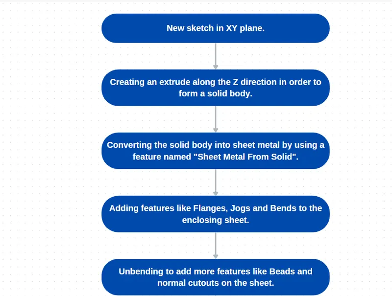
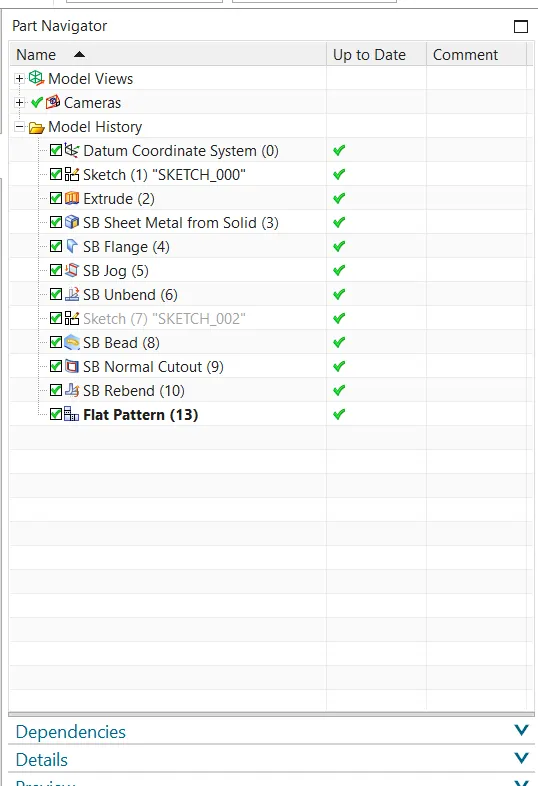
Description:
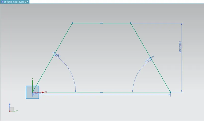
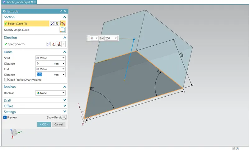
- Sketching and Extrude: In this step we'll create a base sketch and we will do extrude of it upto 200mm.
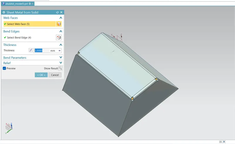
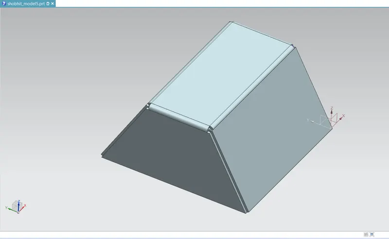
- Sheet metal from solid: In this procedure we will wrap the solid body with sheet metal that means we will convert the extruded body into 3mm sheet metal body
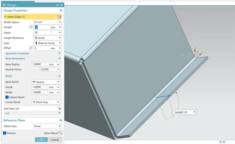
- Flanges: Now we will add 20mm flanges with 90 degrees of inclination from the primary wall.
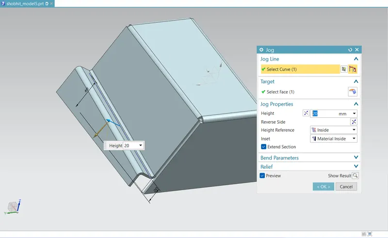
- Jog: Using this feature we will be able to create a step on the side wall of the sheet metal model. This feature is created along a line which is sketched on the same wall plane.
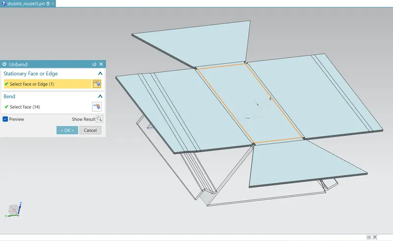
- Unbend: Now in this step we will ubend the sheet metal part in order create feature that needs the model to be flattened.
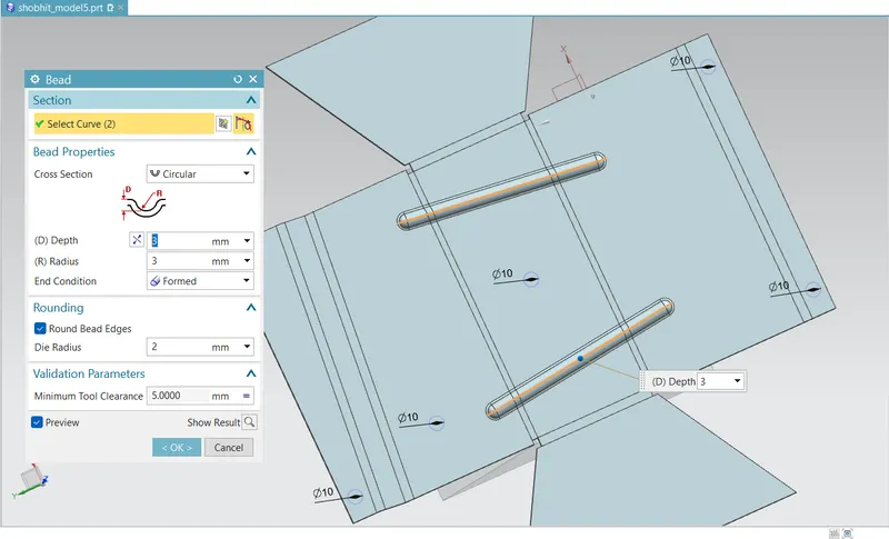
- Bead: At the top face of the model we will create a bead of 3mm depth as well as radius.
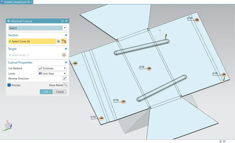
- Normal cutout: We can use this feature to create a hole at the desired location of the sheetmetal model. We can also use Hole command.
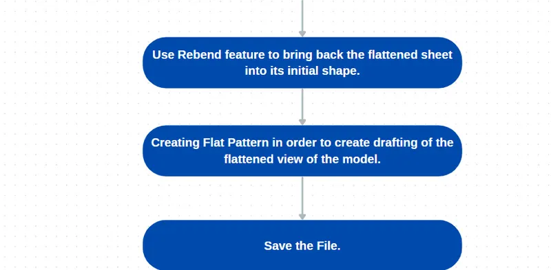
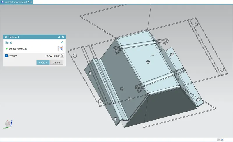
- Rebend: The next step will be to rebend the model in order to bring it back to its initial shape.
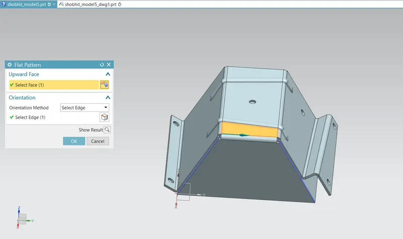
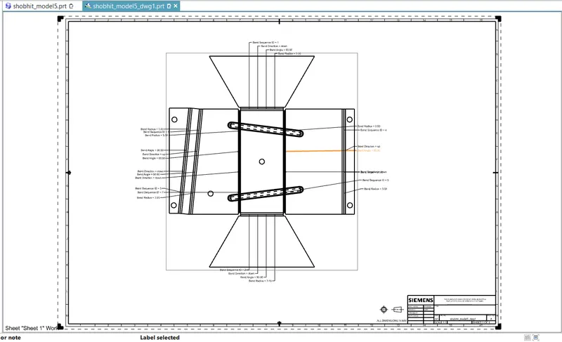
- Flat Pattern: Finally, we'll create a flat pattern for highlighting all the features involved into this sheetmetal model in a flattened view in drawing file.