Week 9 - Project 1 - Door Applique Design with Engineering Features
DESIGNING DOOR APPLIQUE WITH LOCATERS AND HEAT STAKES
OBJECTIVES:
- To create tooling axis using class A surface of door applique.
- To create solid part model out of class A surface of door applique and door panel.
- To create attachments on the door applique models i.e locators and heat stakes.
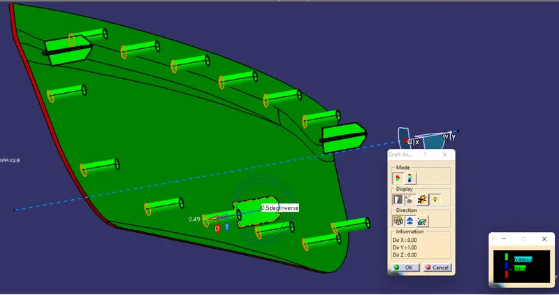
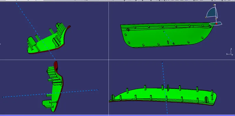
- To do draft analysis of the whole model including the attachments.
INTRODUCTION:
Heat Staking: Thermal staking is an assembly method that uses controlled melting and reforming of a plastic stud or boss to capture or lock other plastic or metal component of an assembly in place. The plastic stud protudes through hole in the component to be locked in place. The heated thermal tip contacts the top of the stud which melts and fills the volumes of the tip cavity to produce a head locking the component in place.
The continous melting of the plastic under the continous pressure forms the head. In heat staking the right combination of heat and pressure for the application is critical.
Advantages of heat staking:
- simplification of machinery
- Reduced cost of machinery
- Multiple fastening points
- Allows higher desity of welds compared to hot air foam and ultrasonic welding.
Locators: Locators are the mechanical features attached to the class B surface of a plastic component. This mechanical feature allows us to arrest eleven degrees of freedom out of twelve, so as to make sure that the component remain fixed to its position in the assembly. The remaining last degree of freedom is arrested by the help of heat stakes.
DESIGNING METHODOLOGY:
CREATION OF TOOLING AXIS:
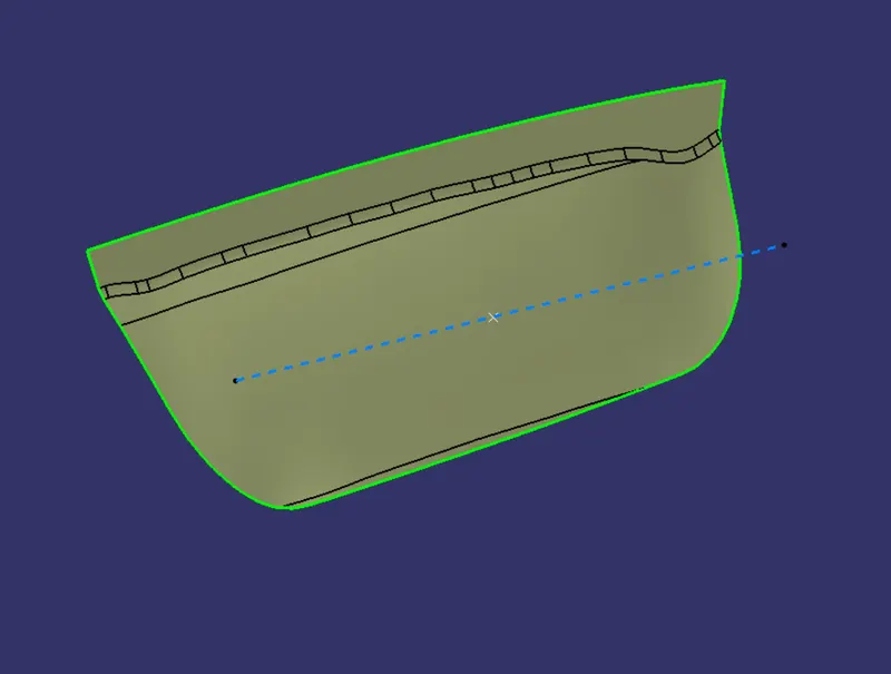
- Take the class A surface of the door applique and create a point using "on the surface" option.
- Create a line using "point-direction" option and select the point create in first step and choose Y direction.
- The resulting line is the tooling axis for the door applique model.
CREATION OF SOLID BODY:
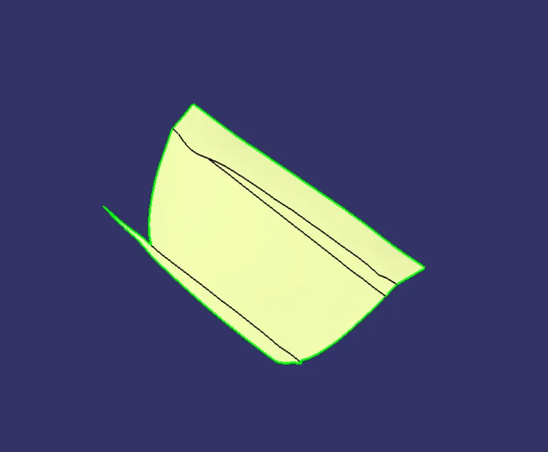
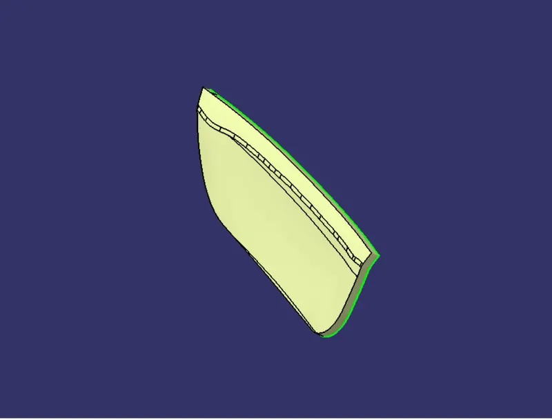
- First start with the preparation of class B surface by extracting all the constituent surfaces of the class A surface and then use untrim command to bring them into their basic form.
- Use extrapolate command to extend their dimensions all over and then use offset surface command to offset the extrapolated surfaces upto 2.5mm in inward direction to the class A surface.
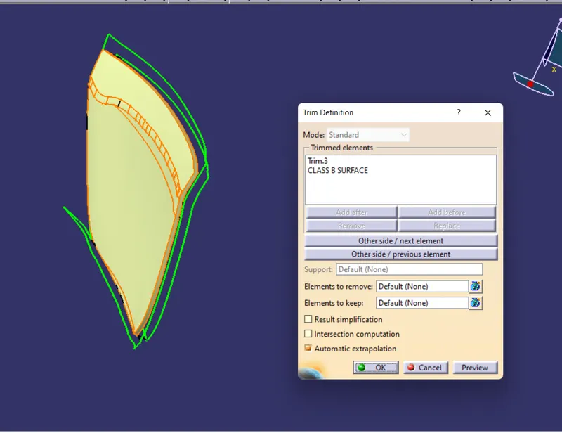
- Trim the all the surfaces one by one untill they form a single entity and then apply fillet to the corners. The resulting surface we would get is the class B surface.
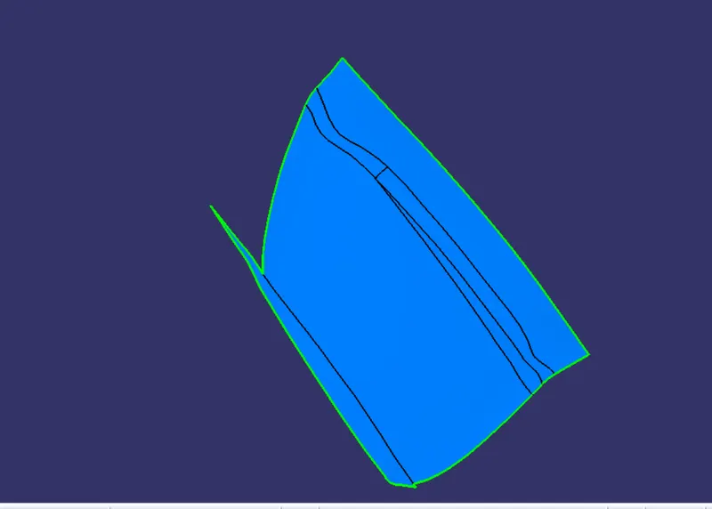
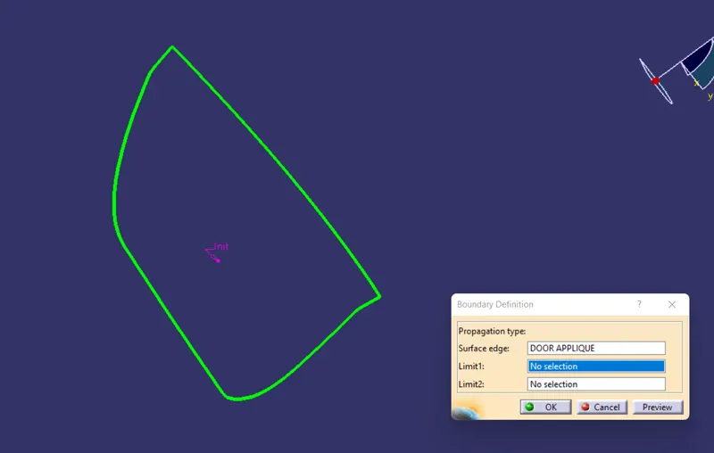
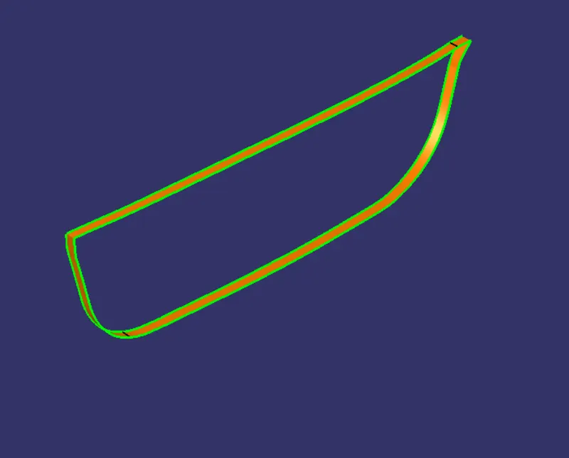
- In order to create class C surface firstly we will use boundary command on the class A surface to extract the boundary curve of the class A surface then we'll use the sweep command using "with draft direction" option and select the boundary as the guide curve and choose tooling axis as the draft direction.
- Join class A surface with class C surface and make sure no gap remain between the adjoining edges of class A and Class C.
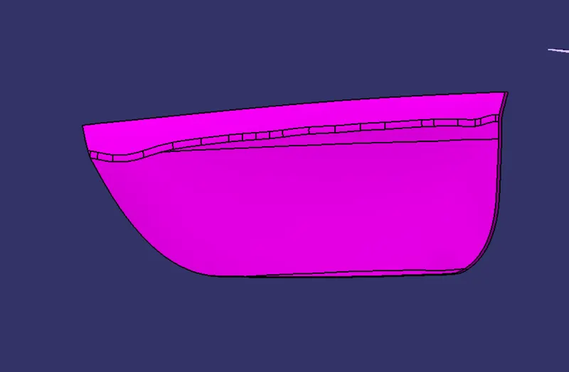
- Finally trim the resulting join of class A and class C surfaces with the class B surface and the resulting entity we would get is our shell model of the door oblique. Go to the part design workbench and use closed surface command in order to fill the shell body with material which will called as the solid body part of door oblique.
DESIGNING OF LOCATORS:
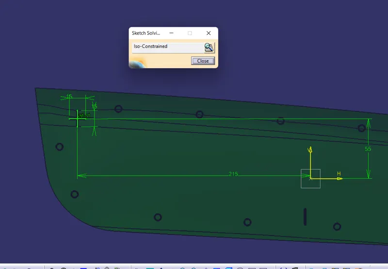
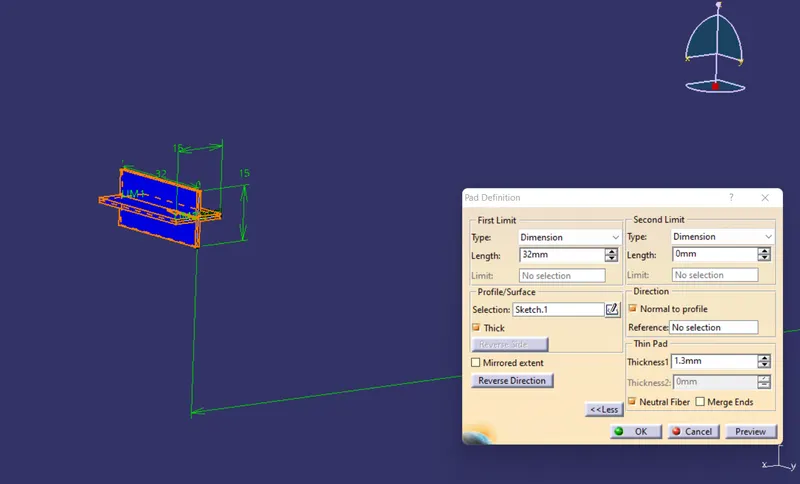
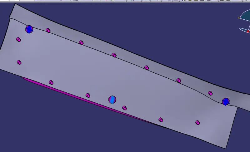
- Create a positioned sketch in order to form four way locator profile(two lines of 15mm bisecting each other perpendicularly) on a plane created paralled to the XY plane and on the point intially created in the middle of door applique surface.
- Use "PAD" command on the above made sketch and click on thick checkbox to thicken the profile by 1.3mm with neutral fiber on. Make sure that the length of the locator easily crosses the door applique body.
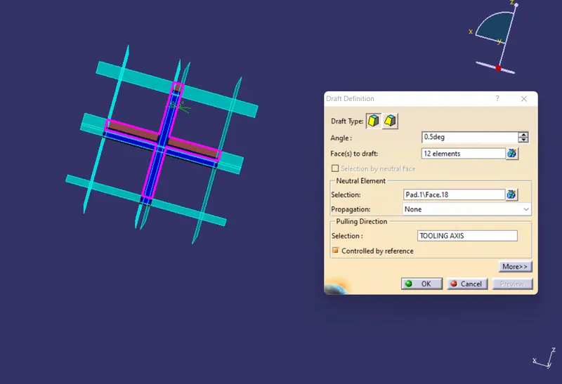
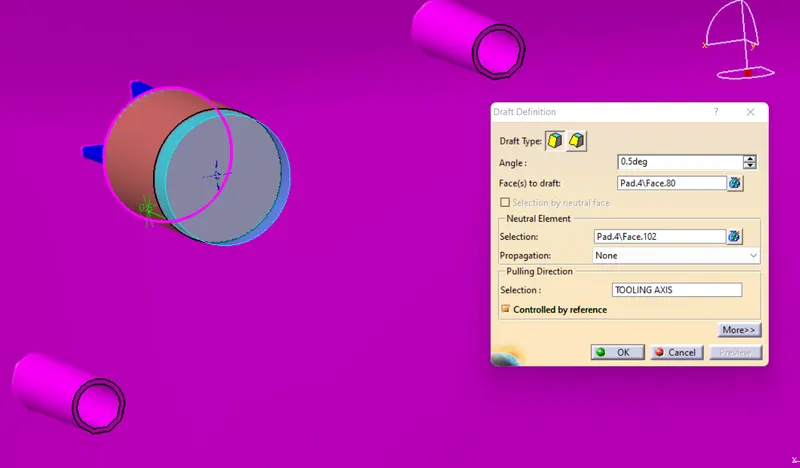
- Apply a draft of 0.5deg along the tooling axis and apply chamfers of length of 5mm and 45deg angle to the top 4 corners.
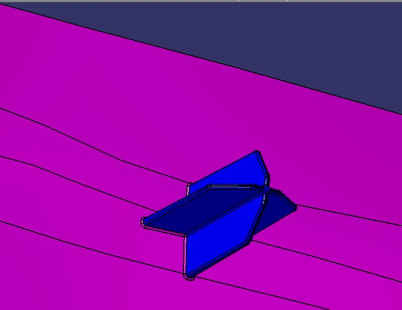
- After applying fillets to all the edges of the locator use "union-trim" boolean operation to join the locator part body with the door applique part body and removing the undesired faces at the same time.
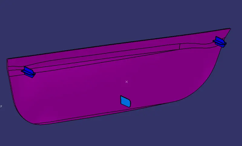
- Similarly create another four way locator on the same point by simply copy pasting the earlier built locator part to the part file and then use translate command to translate the pasted locator part body to the other corner of the door applique.We can do the translation simply using the coordinate method.
- In the same manner create the two way locator in lower middle portion of the door applique.
FORMATION OF HEAT STAKE ATTACHMENTS
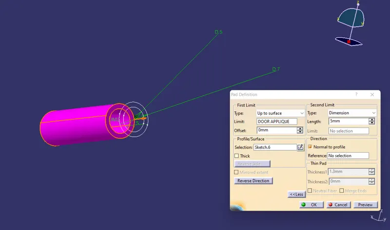
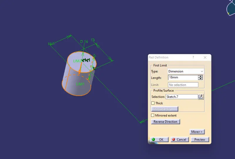
- To create heat stake first create a positioned skecht and create the profile(two concentric circles, smaller one with 5mm dia and 7mm dia for the larger one) for the heat stake in it.
- Apply "PAD" command to the above made sketch and which will result into a cyclindrical body, make the direction of pad towards the applique surface and make sure that the pad crosses the applique body very well.
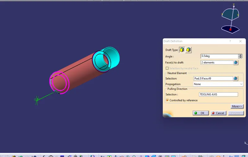
- Now provide a draft of 0.5deg to the resulting pad taking one of the base as the neutral element and make the pulling direction along the tooling axis.The resulting body formed is called as the heat stake.
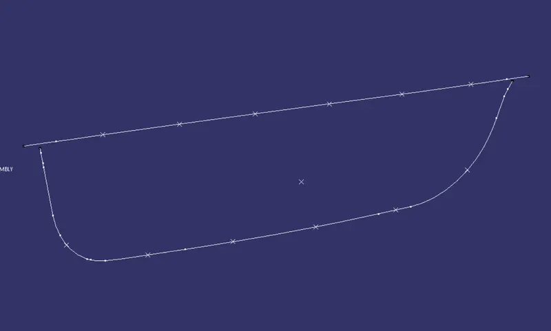
- Since we need a number of heat stakes all over near the boundary of the door applique, we will first create repeated point on the parallel curves created from the boudaries of the class A surface.
- Then we will translate the copies of the initially built heat stake part body to all the points created around the door applique boundary.
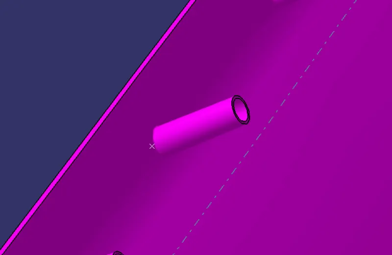
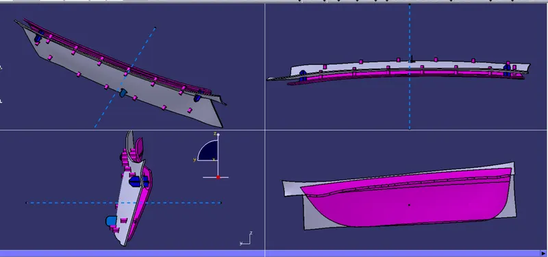
- Assemble all the pasted heat stake bodies to the original heat stake body by ussing "assemble" boolean operation and finally join the set of all heat stake bodies to the door applique body by using "union trim" boolean operation.
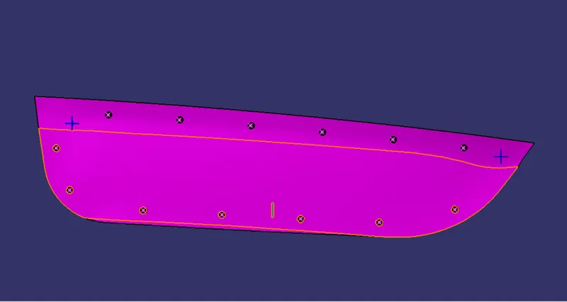
CREATION OF COUNTER PART OF LOCATORS AND HEAT STAKES
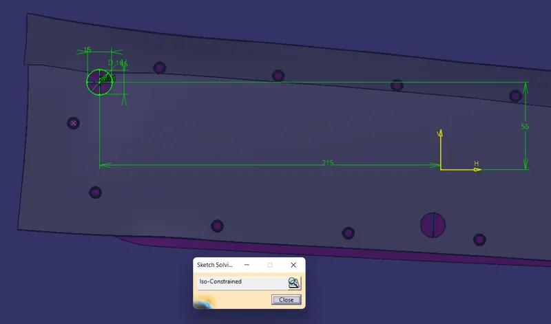
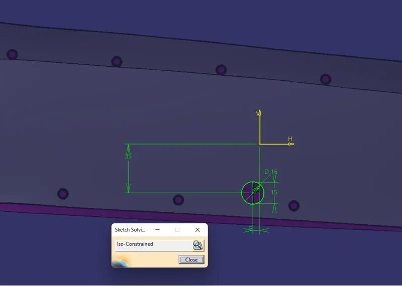
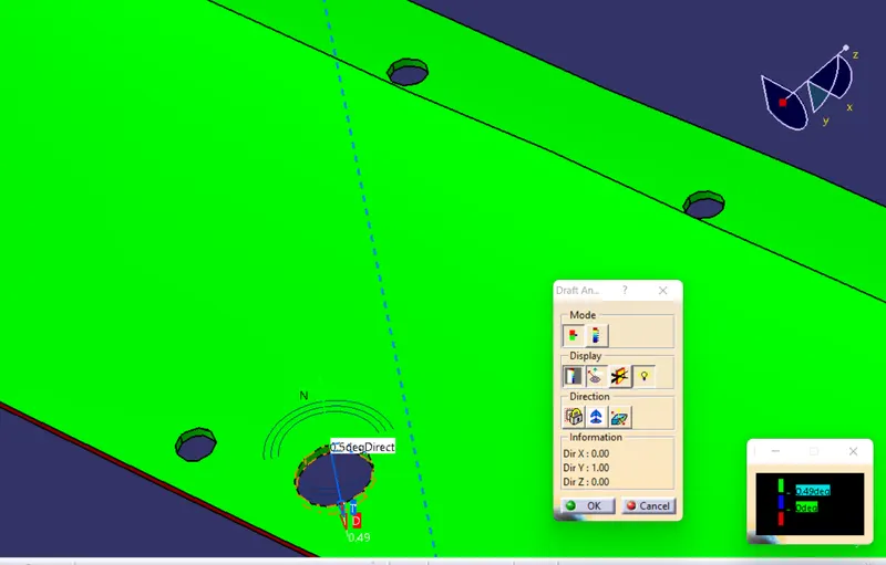
- For creating counter parts for the locators in the door pannel, copy paste the positioned sketch made for the four way locator and create a circle at the centre point of the locator profile such that a minimal gap of 0.5mm is maintained between the locator and the counter part.
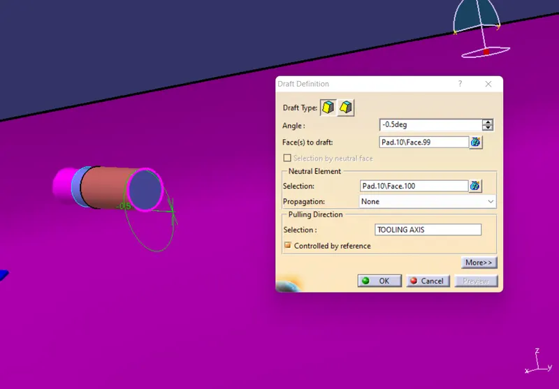
- Use "Pad" command on the sketch and make sure that the pad crossed the door pannel, after that apply draft of 0.5deg to it.
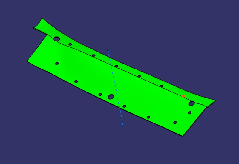
- Again use ''remove" boolean operation to remove the resulting pad from the door pannel it would create a hole with a gap of 0.5 from all the outer faces of the locator.
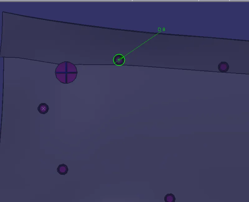
- In the same manner create the counter parts for the rest of the two way locator and all the heat stakes. In the case of heat stakes take the help of the repeated points made on the parallel curve to translate the rest of the counter parts.
DRAFT ANALYSIS FOR THE DOOR APPLIQUE
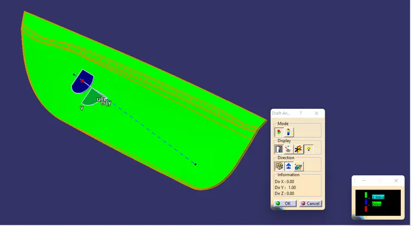
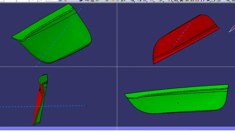
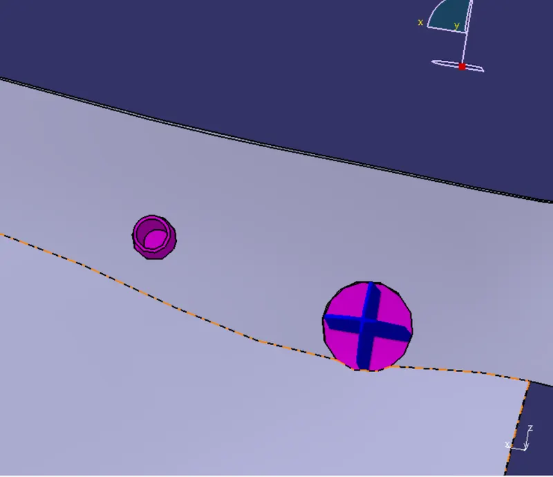
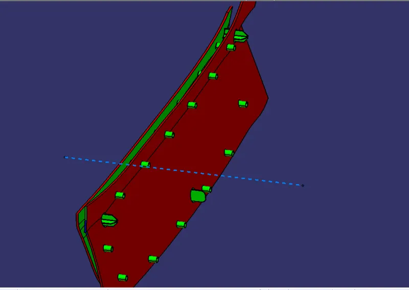
DRAFT ANALYSIS OF LOCATORS AND HEAT STAKES
DRAFT ANALYSIS FOR COUNTER PARTS
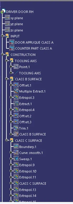
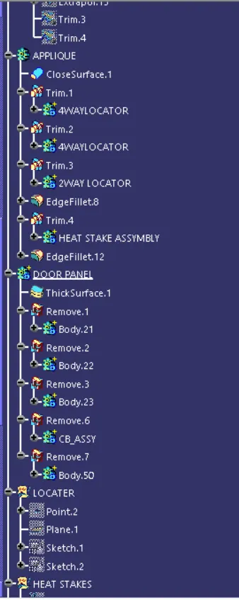
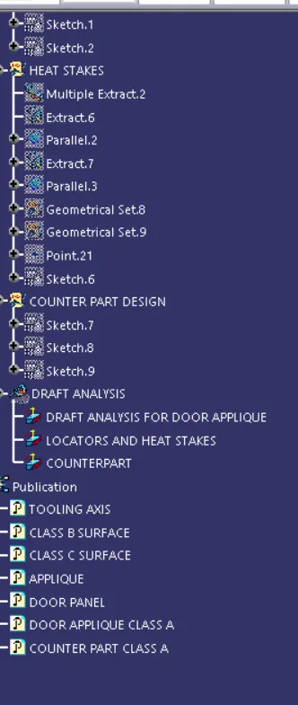
TREE STRUCTURE