Advanced Sheet Metal Design Using NX Cad Challenge_7_ Metal bracket-II
TITLE OF THE PROJECT: Advanced Sheet Metal Design Using NX CAD Challenge_7_Metal Bracket-2.
OBJECTIVE: To design a Metal Bracket-ll by using Siemens NX12 Sheet metal application.
INTRODUCTION:
Sheet Metal is basically a sheet made out of metal like steel through a forming process called rolling and the thickness of sheetmetal starts from 0.5mm and goes upto 6mm. Sheet metal is one of major input material used in automotive manufacturing industries and several other industries. These sheets are transformed into useful products like BiW frames in automotive industry with the help of various sheet metal operations like bending, punching, blanking, piercing, lancing etc.
Applications: Aircraft bodies, Automobiles bodies, Utensiles used for domestic purpose, Bevarage Cans.
The NX Sheet Metal application provides an environment for the design of sheet metal parts used in Machinery, Automotive, Aerospace etc. Enclosures, brackets and other parts normally manufactured with a brake press.
NX sheet metal application provides a set of tools that allows for easy and fast design of sheet metal parts such as BiW components. NX sheet metal design application incorporates features or commands which are very handy for depicting or representing majority of the mechanical operations involved in sheet metal part formation.
some of the examples of such features are: bends, flanges, tabs, cutouts, beads, dimples, louvers, corner and edge treatments, patterns and other features related to forming process.
Using the NX CAD sheet metal application we can easily convert solid models to sheet metal replica by the technique of wrapping around the sheet of required thickness around the solid model.
Gussets:
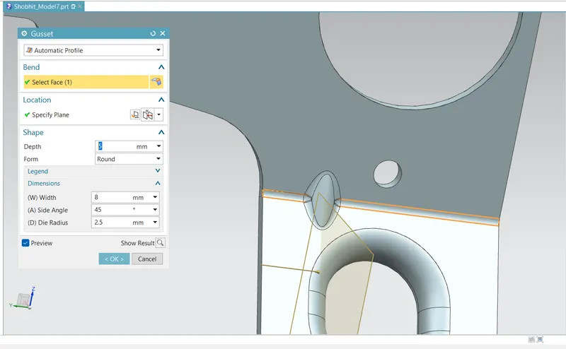
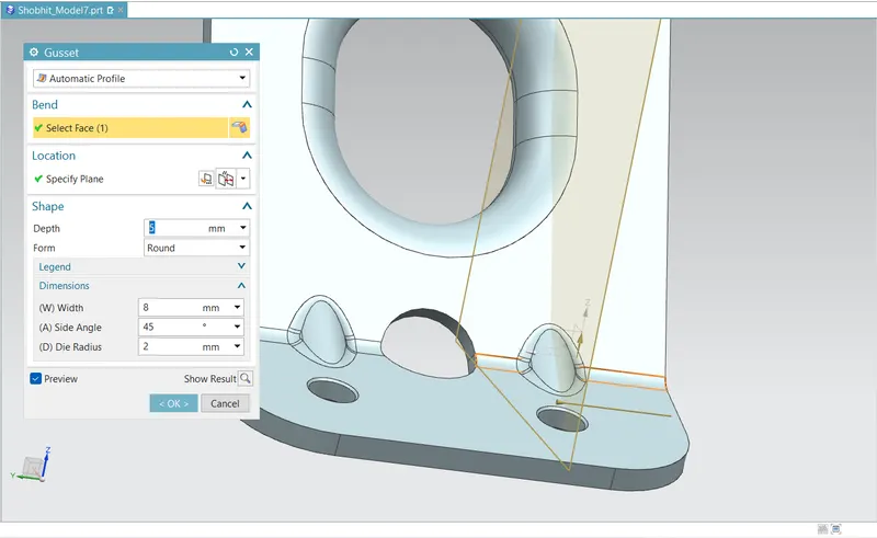
Gussets are used to strengthen a flange without the need for secondary processes such as welding.A general guideline suggests that the width and depth of gusset at an angle of 45 degrees is directly proportional to the radius and material thickness.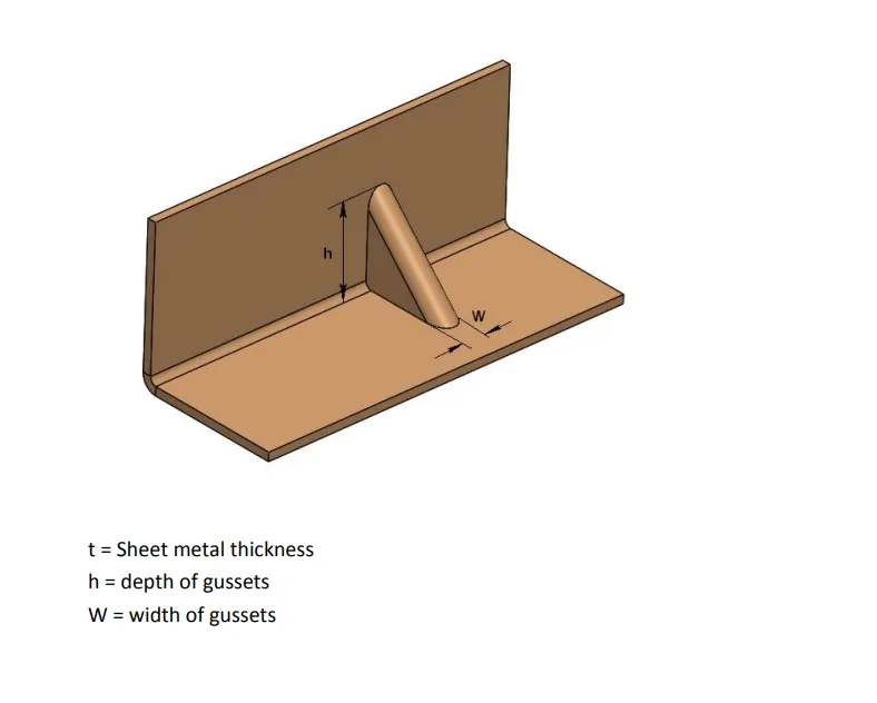
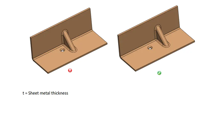
Minimum Distance from Hole to Gusset:
A certain distance must be maintained between a hole and gusset to avoid metal deformation and fracturing. It is recommended that minimum distance between hole edge to gusset should be at least eight times the material thickness.
Minimum Distance from Extruded Hole to Part Edge:
Extruding metal is one of the most extreme pressure applications in press working and generates lot of friction and heat. If an extruded hole is too close to the part edge, it can lead to deformation or tearing of the metal. It is recommended that the minimum distance between the extruded holes to part edge should be at least three times the thickness of sheet.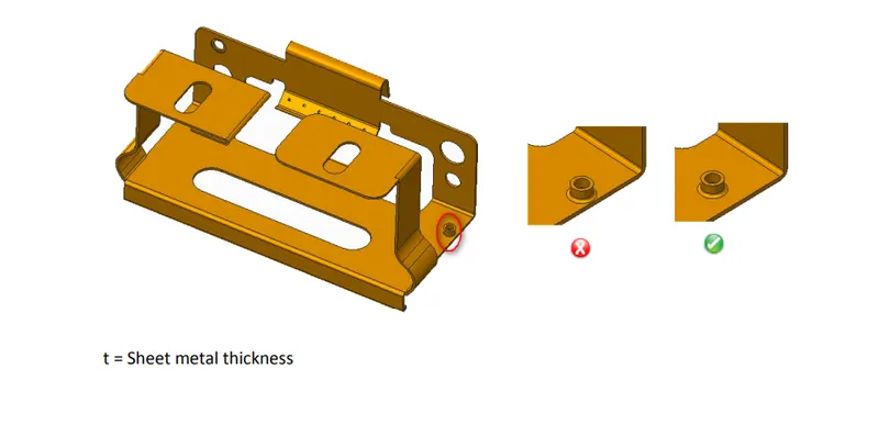
Minimum Distance Between Extruded Holes:
Certain distance should be maintained between two extruded holes in sheet metal designs. Ifextruded holes are too close it can lead to metal deformation. It is recommended that the minimum distance between two extruded holes should be six timesthe thickness of sheet metal.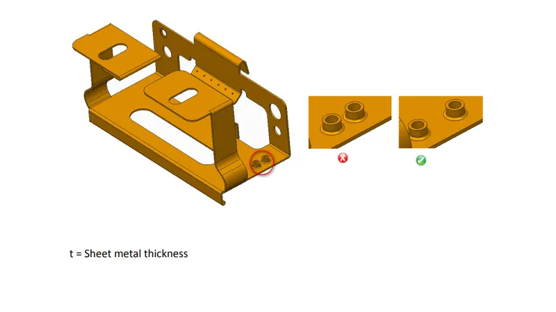
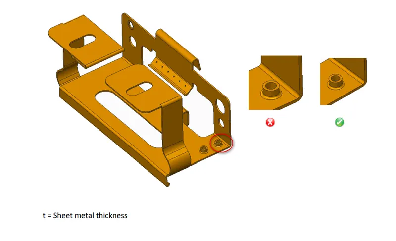
Minimum Distance from Extruded Hole to Bend
A certain distance must be maintained between extruded hole to bend to avoid metal deformation and fracturing. It is recommended that the minimum distance between extruded hole and bend should be three times the thickness of sheet metal plus bend radius.
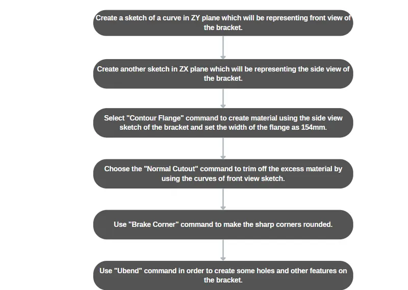
DESIGNING METHODOLOGY:
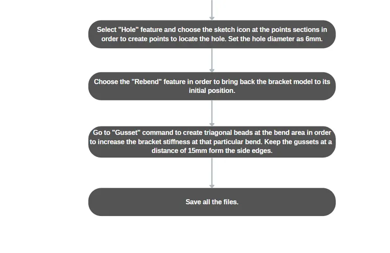
DESCRIPTION:
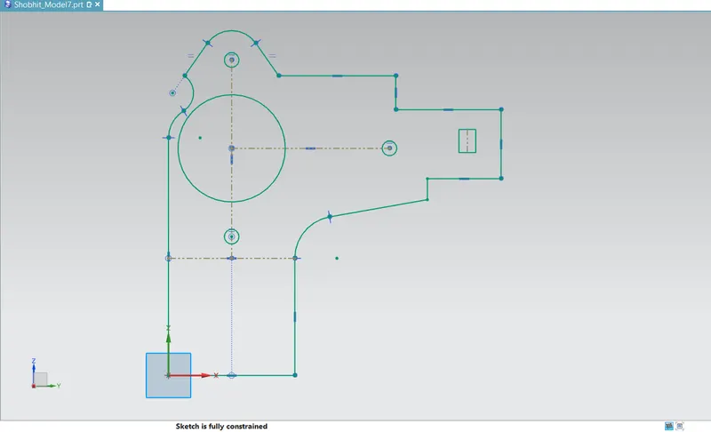
- Sketch in ZY Plane:
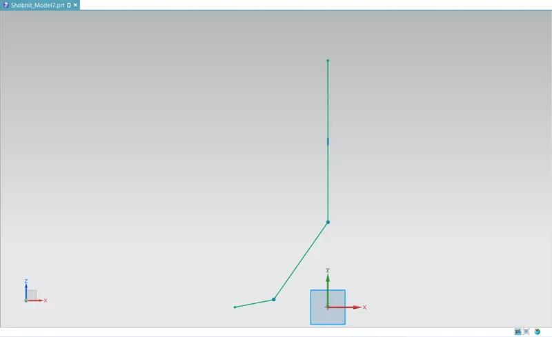
- Sketch in ZX Plane:
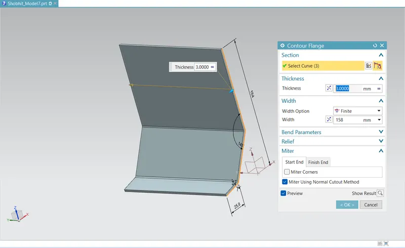
- Contour Flange:
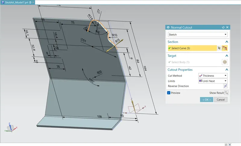
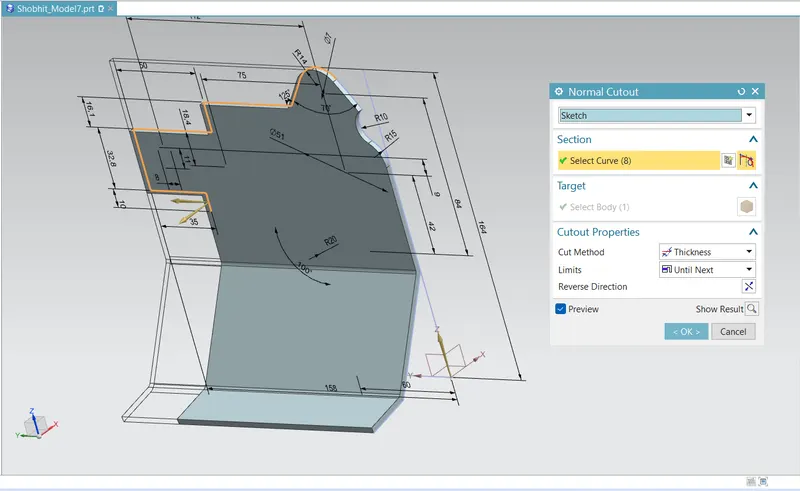
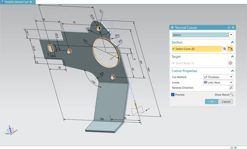
- Normal Cutout:
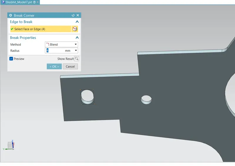
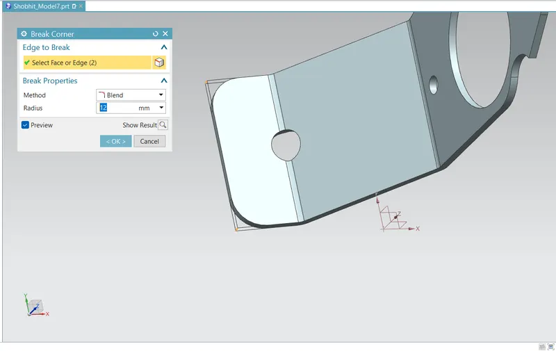
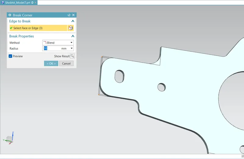
- Break Corner:
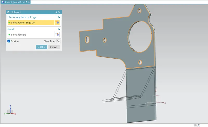
- Unbend:
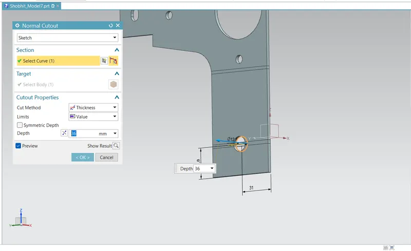
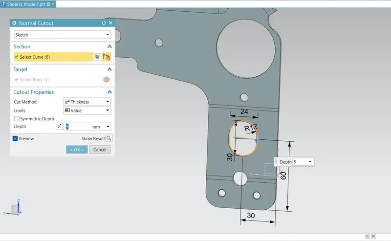
- Normal Cutouts:
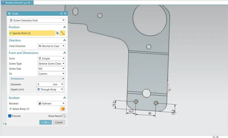
- Holes:
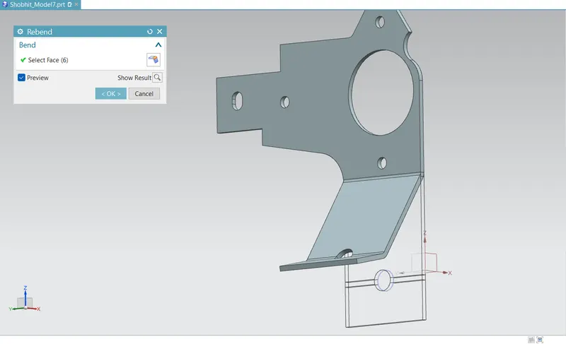
- Rebend:
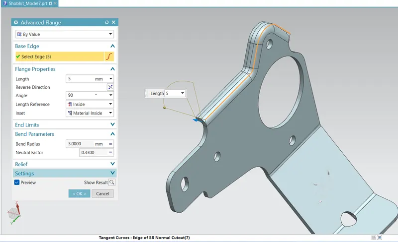
- Advanced Flange:
- Gussets:
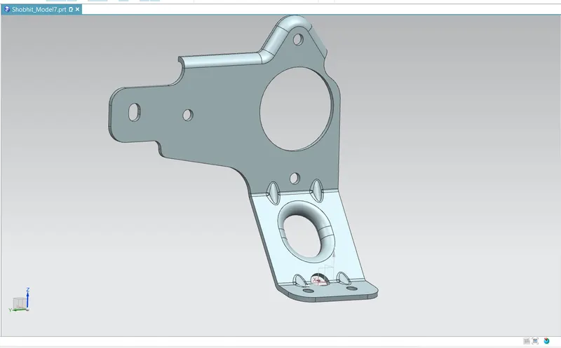
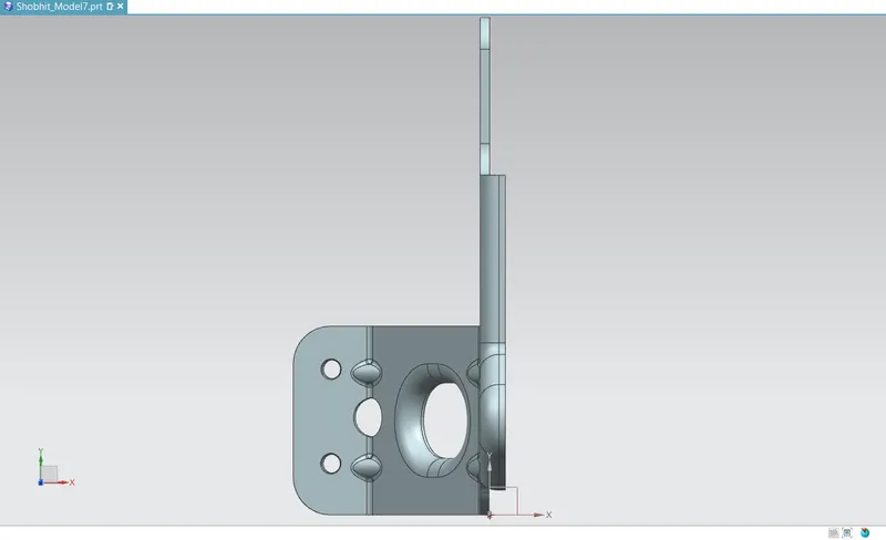
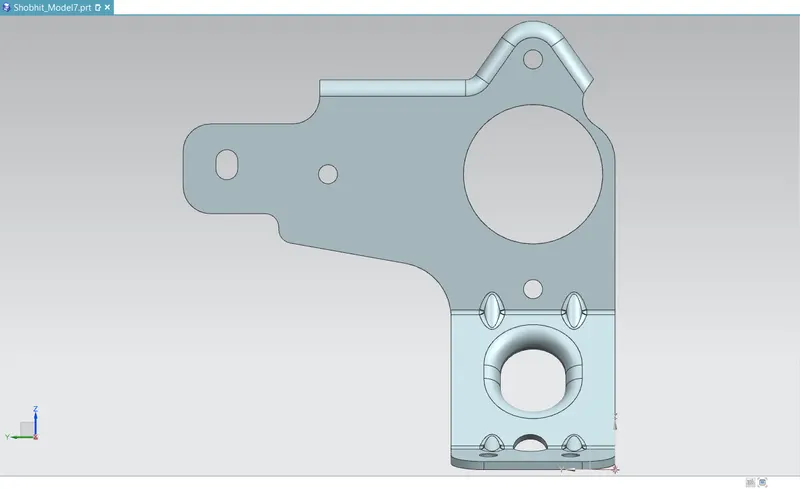
STANDARD VIEWS:
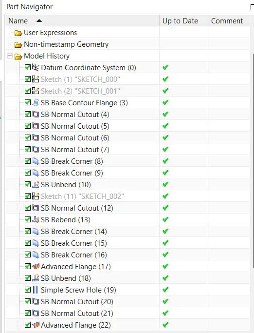
TREE STRUCTURE: