Wiring harness routing & packaging Rules Week 3 Challenge
ELECTRICALLY DEFINING BACKSHELLS, CLIPS AND CORRUGATED TUBES
OBJECTIVE:
- To electrically define the CLIPS OR CLAMS as electrical supports in electrical part workbench.
- To electrically define the BACKSHELLS in electrical part workbench using the geometrical parameters created in part workbench.
- To create the corrugated tubes of various outer dia and defining them as protection part in electrical part workbench.
INTRODUCTION:
CLIPS & CLAMPS: Clips and clamps are used to fix wiring harness bundles by providing positive fixings, these are generally provided in case of offroad vehicles and trucks to give firm fixings.
BACKSHELLS: Backshells are the components that attach to the back of connectors often designed to guide the wires and cables that are terminated at the connector. The backshells are often mated with strain relief components, environmental seals, the shielding.
CORRUGATED TUBES: These are a kind of protection covering which are used to protect wiring harness assembly from mechanical damage and thermal damage by any means in the vehicle environment. They also enhances the overall aesthetic of the wiring harness assembly.
METHODOLOGY:
DEFINING BACKSHELLS:
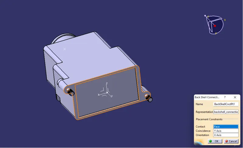
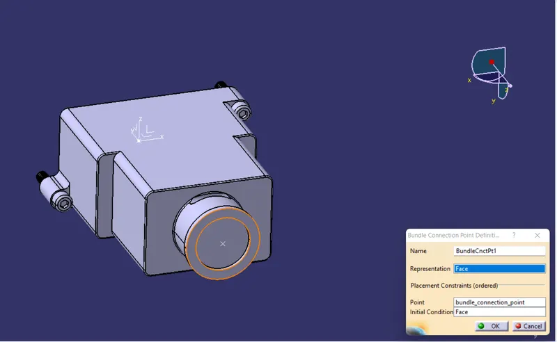
The first step towards electrically defining the backshell is to create necessary geometric parameters which will be representing the backshell connection point and bundle connection point.
The second step would be to switch to the electrical part workbench where we will be defining the backshell connection point and bundle connection point.
Third step includes creating a new catalouge document file and add a family of backshells and choose the type as electrical and save the catalouge document file to any desired and suitable location. Finally we will store our electrically defined backshell in the same catalouge that we just created.
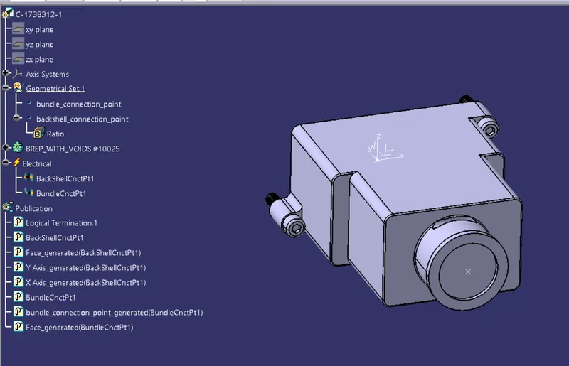
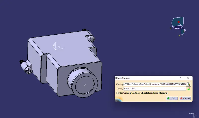
DEFINING CLIP:
Clip is another important wiring harness component which needs to be defined before routing the wiring harness routing. following are the important parameters that needs to be defined:
- Entry Point and Entry Plane
- Base Plane
- Exit Plane
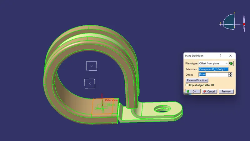
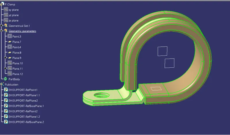
The first step towards defining the clip is to create the required geometric parameters for ENTRY POINT AND PLANE, BASE PLANE and EXIT PLANE in part work bench, these parameters are nothing but points and planes at their required positions.
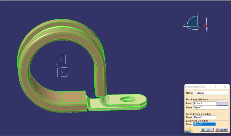
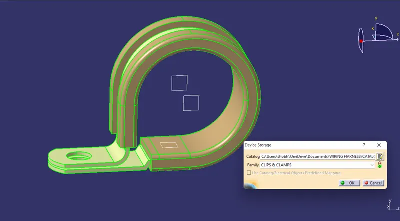
In the next step we will switch to the electrical part workbench and define the clip by using "define support" command, in the support definition dialog box we'll be aksed about first plane definition, second plane definition and base plane definition, so in response to these we we will select the entry point and plane, exit plane and base plane respectively.
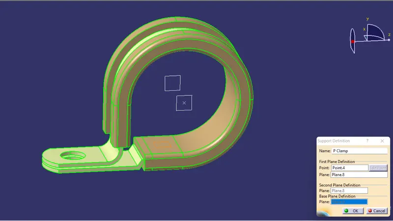
Since the entry and exit of the wire bundles can start and end with any of the sides of the clip so, considering this in mind we'll repeate the same excercise of defining the entry and exit planes from the other side of the clip.
Finally we will store the electrically defined clip in the catalouge document file already created for storing the cad models which can in be included in clips and clamps family.
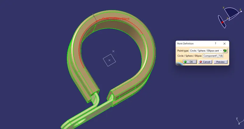
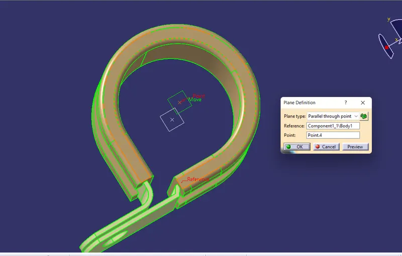
DEFINING CORRUGATED TUBES:
To define corrugated tubes we do not need any part or surface model because in wiring harness routing we just use a representation of corrugated tubes as a electrically defined protection part.
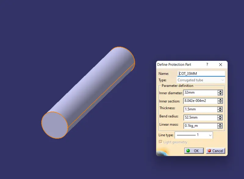
To start defining the protective covering we'll first go to the part work bench and then without doing any thing we'll switch to the electrical part workbench and we'll use the "define protection part" command in order to define the corrugated tubes.
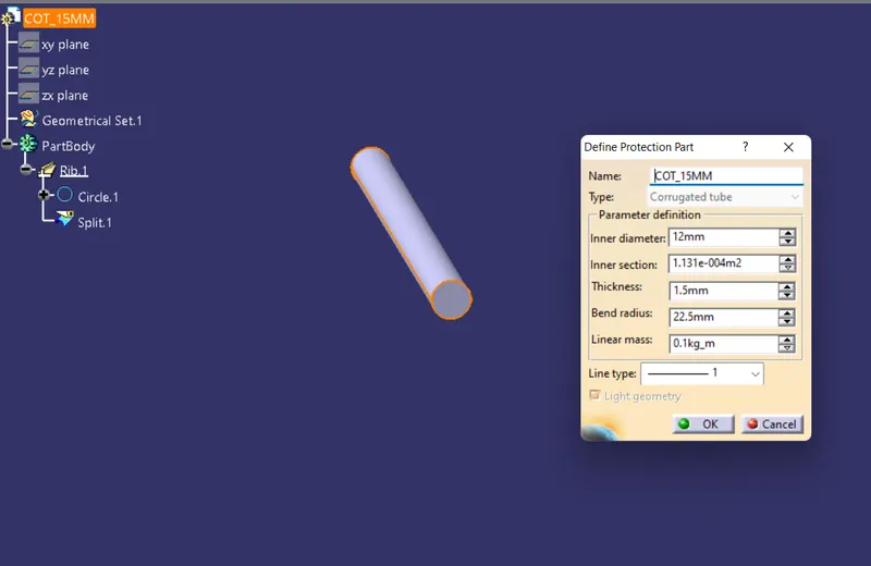
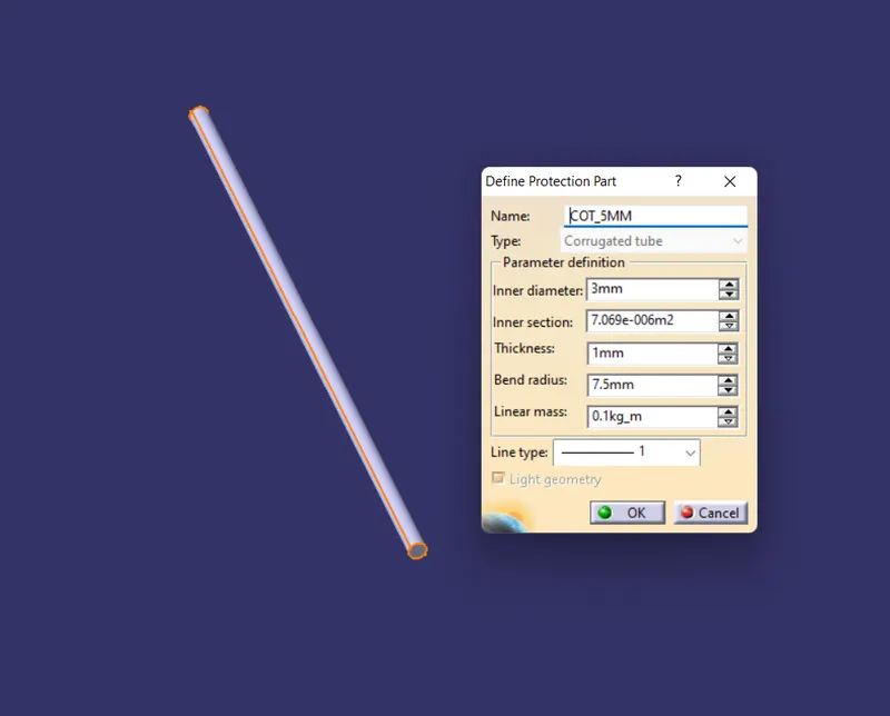
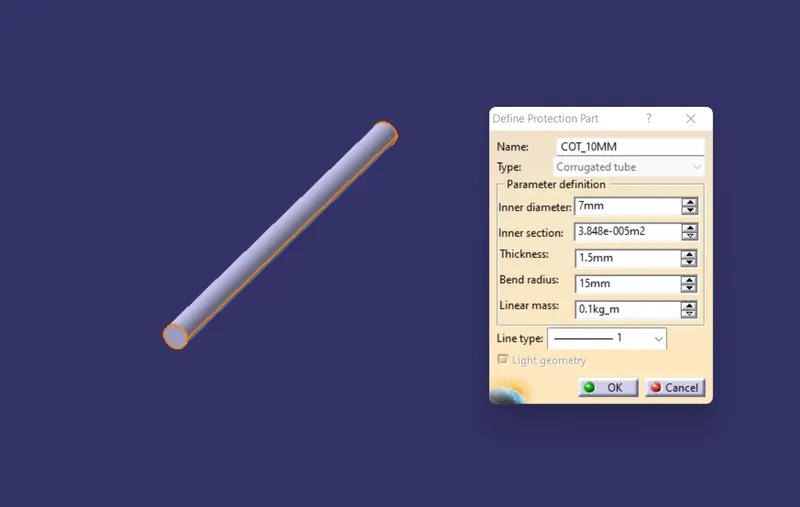
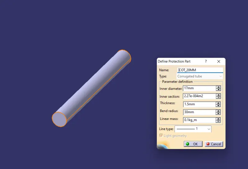
Here in protection part definition dialox box we'll be asked about the inner dia of the COT tubes their thickness and their bend radius(should be 1.5 times of outer dia).
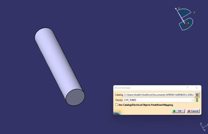
Finally we can store all the COT tubes with different dimensions using "store" command and add all of them in a catalouge document file with a family of COT TUBES.