Wiring harness design in CATIA V5 - 3D modeling Week 2 Challenge
DEFINING WIRING HARNESS COMPONENTS AS ELECTRICAL COMPONENTS IN ELECTRICAL PART WORKBENCH
OBJECTIVES:
- To download the connectors and connector clips CAD data from any of the wiring harness supplier's website ie. te.com.
- To define the connectors and connector clips as electrical connectors and mountings respectively using electrical workbench in CATIA V5.
- To create a catalouge for the defined components in catalouge document file.
INTRODUCTION:
WIRE HARNESS: A wire harness, often referred to as cable or wiring assembly, is a systematic and integrated arrangement of cables within an insulated material. The purpose of the assembly is to transmit signal or electical power to various electrical components of a vehicle.The wire harness simplifies the connections to larger components by integrating the wiring into a single unit for "drop-in" installation.
WIRING HARNESS TOPOLOGY:It is a strategy to divide or split the harness between different pieces to achieve the best manufacturability, serviceability and cost effective design.
WIRING HARNESS ROUTING:wiring harness routing deals with desired path of wiring harness into given environment by applying set of design rules and industry best practices.
WIRING HARNESS PACKAGING:wiring harness packaging deals with fixing/mounting stategy of wiring harness routing to ensure the safe, reliable and durability of wiring harness by applying set of design rules and industry best practices.
CONNECTORS: connectors are responsible to make contact between wiring harness and components or between two different wiring harness assemblies by offering mecanical locking and sealing to joint.
TERMINALS: Terminals are crimped joints to wire to make mechanical connections with connectors and devices more reliable and durable. Terminals are electroplated to offer minimum contact resistance and anti corrosion protection.
CLIPS and CLAMPS: clips and clamps are used to fix wiring harness bundles by providing positive fixings.
RETENTION DEVICES: Retention devices like connectors mountings clips, connectors , secondary locks are respectively used to provide mechanical fixing, locking to the connectors and terminals. Connector backshells are used for good appearance and bunddle dressing in critical area.
METHODOLOGY TO DEFINE THE WIRING HARNESS COMPONENTS
CREATING GEOMETRIC FEATURES
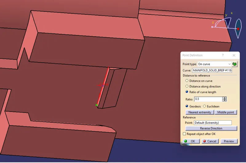
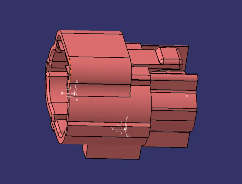
Before defining the connectors and connector clip as electrical components we'll first need to create some geometric features like points and axis system in order to represent the bundle connection point, connector connection point and and cavity connection point.
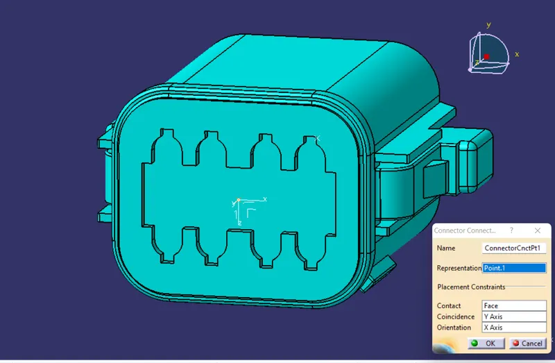
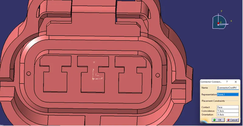
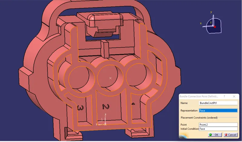
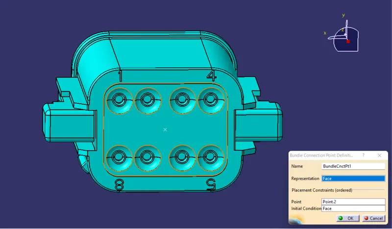
We'll create one point at the center position of the face of connector model which is going to come in contact with another connector or device at the time of assembly, this point is going to be defined as connector connection point. One another point we'll create at the center position of the face of connector which will come in contact with wire bundle and this point will be represented as the bundle connection point.
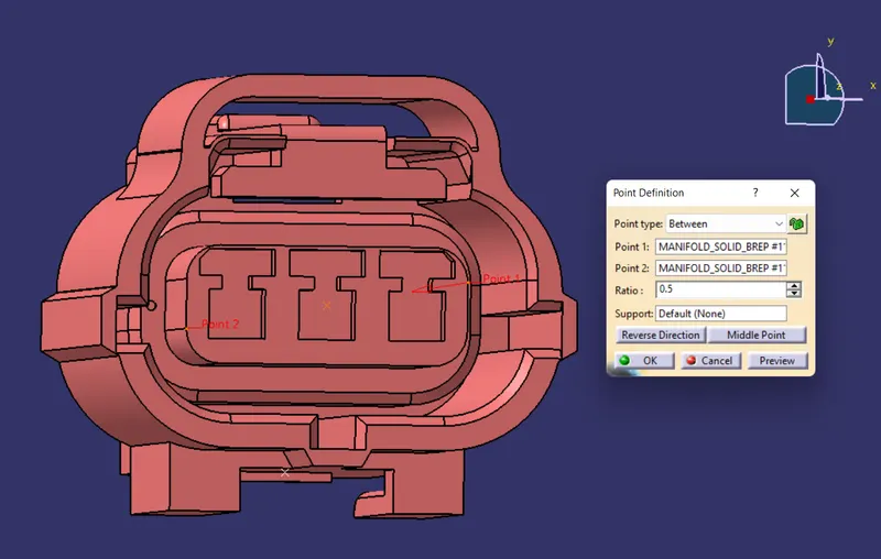
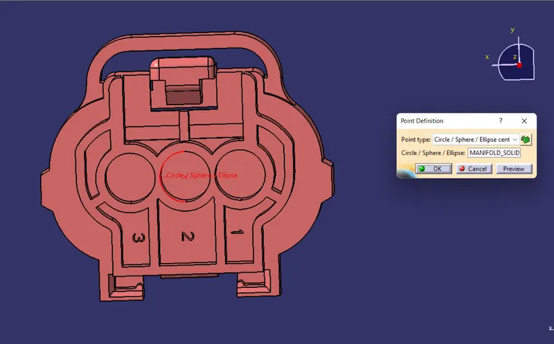
We'll further create an axis system taking connector connection point as its origin and we'll orient the the Y axis of the axis system along the mating direction of the connector either with its mating connector or with some device. The X axis will be oriented towards the locking direction of the connector with its matting part. This is a convention that we need to follow every time we create any axis system for defining the wiring harness components.
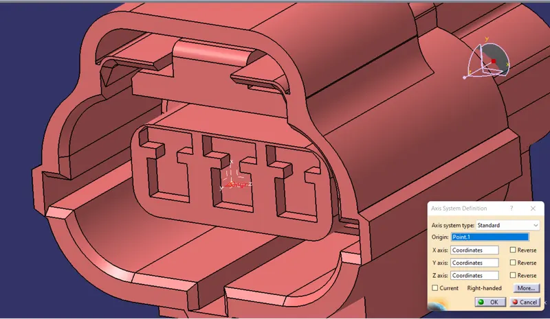
There is one another point called cavity connection point is also created in cases of the connector contains the cavity for mounting clips and clamps. For defining the cavity connection point we need to create an axis system which will be oriented in the similar manner as in the case of connector connection point.
DEFINING CONNECTOR AND ITS CONNECTION POINTS IN ELECTRICAL PART WORKBENCH
To define the connectors and its corresponding connection points first we need to switch to electrical part workbench of CATIA V5 here we can find the required tools to define the wiring harness components electrically.
Following are the steps to define the connector and connector clips and subsequently their respective connection points:
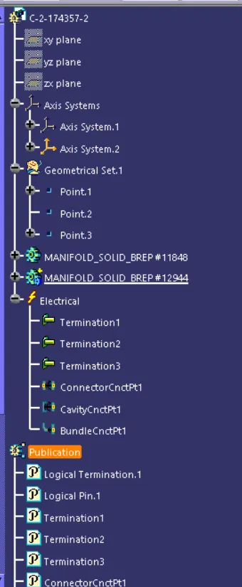
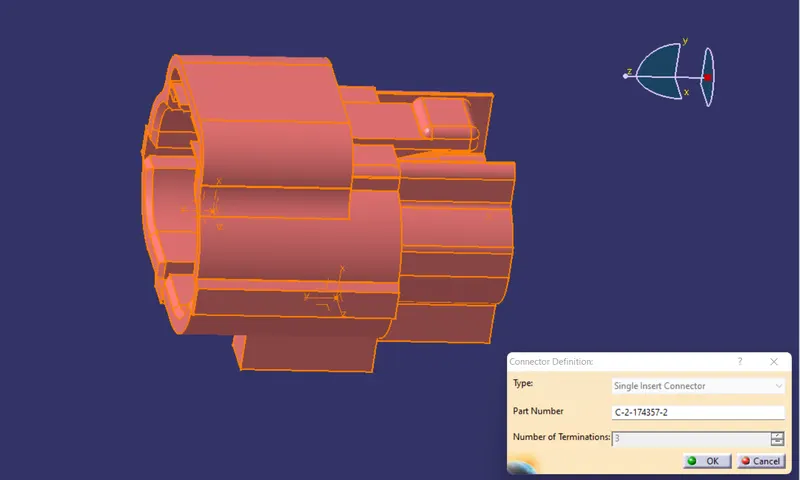
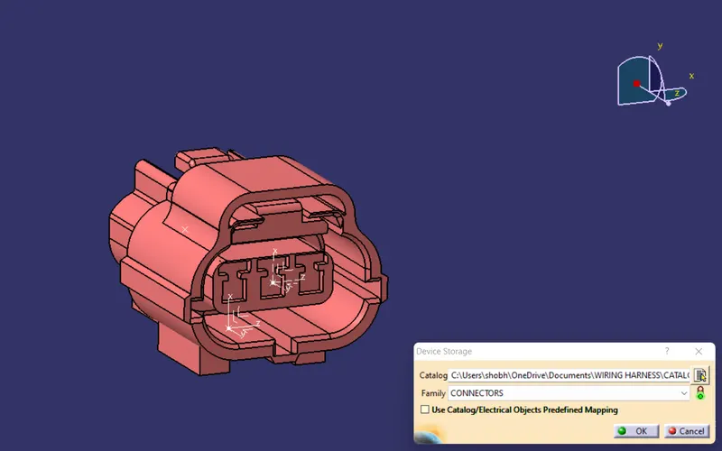
1. In case of connectors we'll the define it using the "define connector" command. In the connector defination dialouge box we'll be asked about the type, part number and number of terminations. So as we can see the connector shown in the pic below is having three no. of terminations and it is a single insert connector and in place of part number we can type the connector series no provided by its supplier.
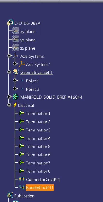
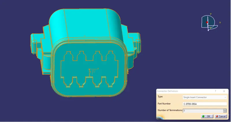
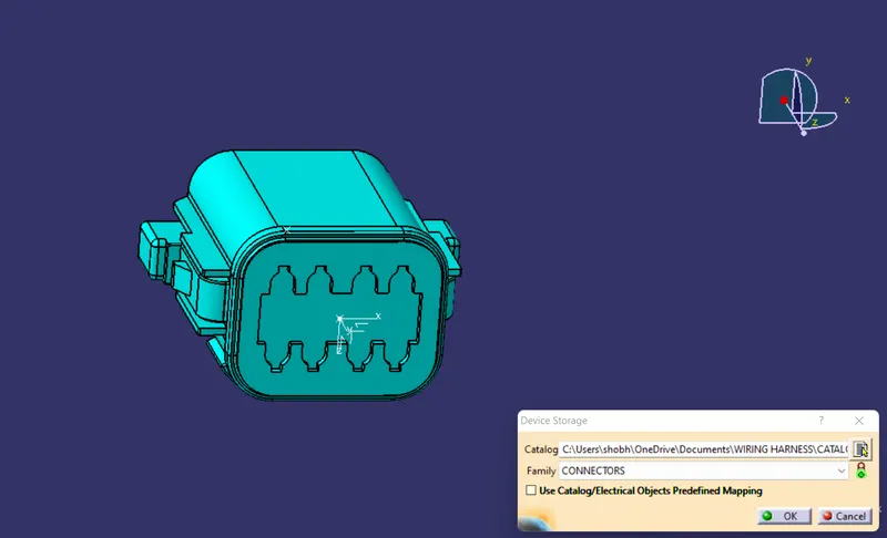
In this case we can see that the connector is having eight termination points so while defining this connector we'll tpye 8 as the number of terminations. Some of the important things that can be noticed in this connector is that it is not containing the cavity for mounting feature like clips and clamps in it and secondly it is having the locking mechanism on its side walls.
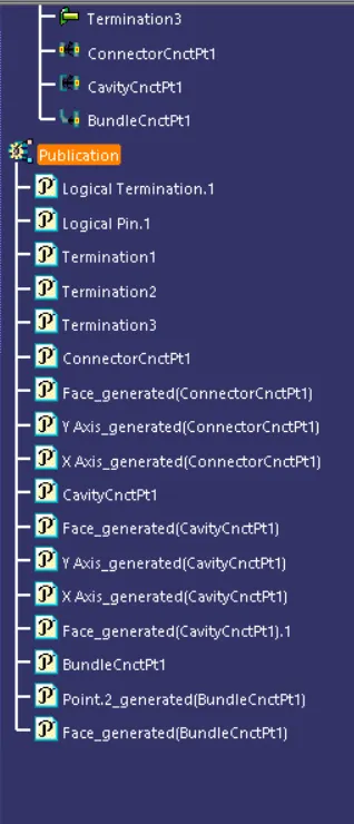
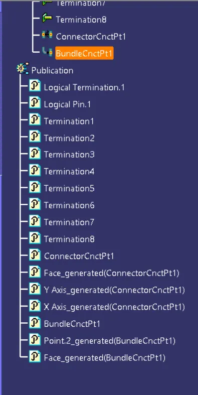
2. The second step would be to define the various connection points on the connector for which we have already created the geometric features like points and axis now we just need to define them electrically. In order to define various connection points we have different command available to us like connector connection point, bunddle connection point and cavity connection points. So here we'll use these commands one by one.
DEFINING CONNECTOR CONNECTION POINT
DEFINING BUNDLE CONNECTION POINT
DEFINING CAVITY CONNECTION POINT
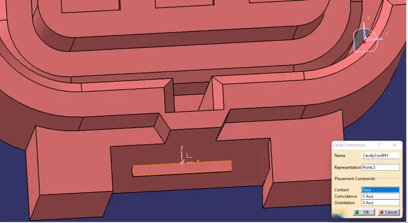
DEFINING CONNECTOR CLIP AND CAVITY:
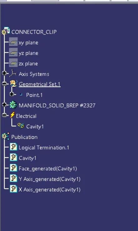
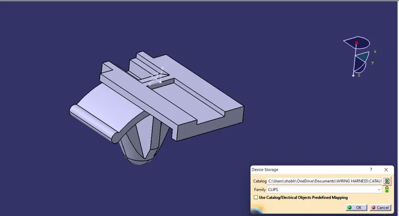
Since we are using the connector clips as the mounting for the connectors so here we need to define the connector clip as a mounting component, in order to define the connector clip we will take help of "mounting" command in electrical part workbench.
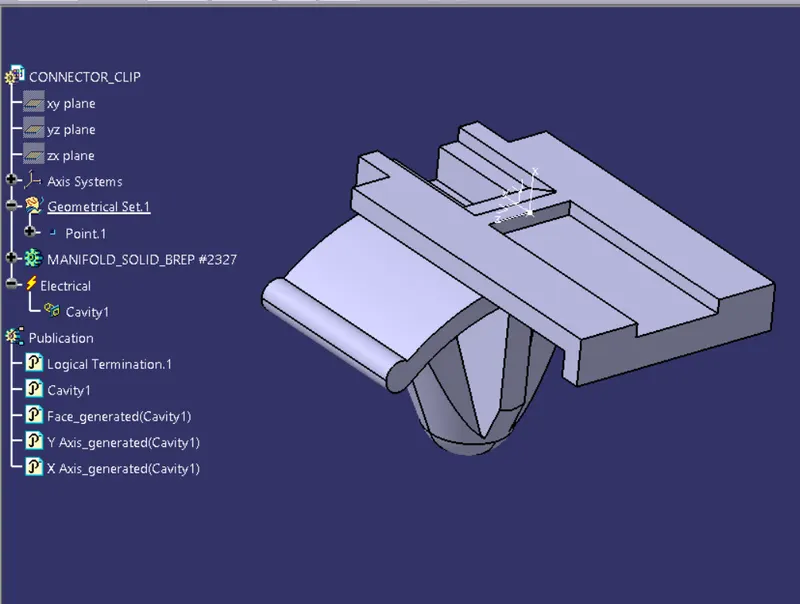
In case of connector clip we don't define cavity connection point instead of this we define cavity for the connector clip because connector clip has the required cavity on which the connector is being mounted, while defining the cavity we need to follow exactly the same axis system as in the case of cavity connection point.
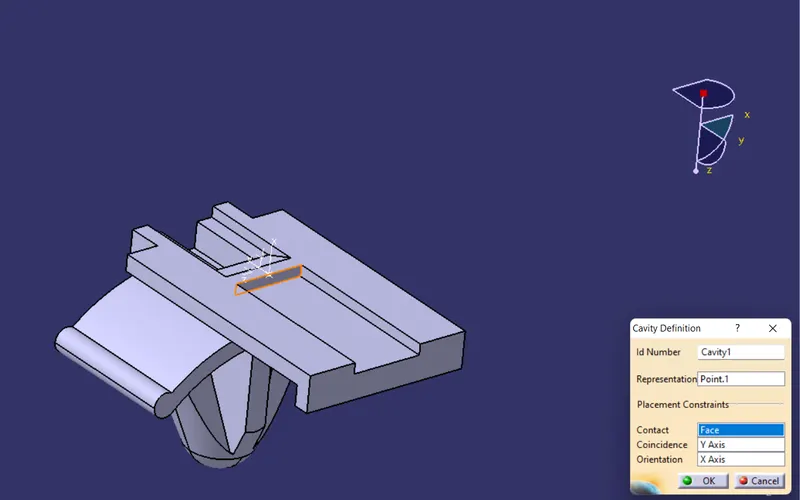
CATALOUGE CREATION:
Creating catalouge has great benefits it allows one skilled wiring harness engineer to do one time effort in designing and defining the wiring harness components and assembly and this data can be saved as a catalouge document which can be resused n number of times by the other engineers all over the organisation.
Go to new select "catalouge document " then selelct "add family" command.
Choose the family and type of the component as shown in the figure below.
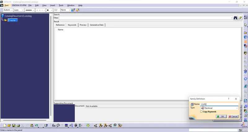
Then we will store the electrically defined component in their respective family of catalouge using "store" command.
ELECTRICAL DEFINITION DATA: