Roof challenge
AUTOMOTIVE ROOF DESIGN AND ANALYSIS
OBJECTIVE:
To design a car roof assembly along with its constituent parts i.e outer panel, front roof rail, center roof rail, bow roof rail and rear roof rail by taking references from the master section given to us as an input for each part and doing various strength analysis on the designed components in order to check their feasibility under extreme weather conditions.
INTRODUCTION:
An automobile roof or car top is a BiW portion of an automobile that sits above the passenger compartment, protecting the vehicle occupants from sun, wind, rain and other external elements.
It also protects the passengers from getting serious injuries in cases of car getting rollover. Vehicle roof is subjected to the rollover accidents which are most dangerous among all kinds of accidents since it is directly attack occupant's head and neck hence risk to life is more.
TYPES OF ROOFS:
HARDTOPS: These are common rigid automobile roofs normally seen in most of the cars which are either made of metal or plastics. The different types of these roofs that are used in convertibles are mentioned below
- Detachable Hardtops: This type of hardtop is manually removed from the roof and then stored usually in the trunk. They are also made from metal or plastics.
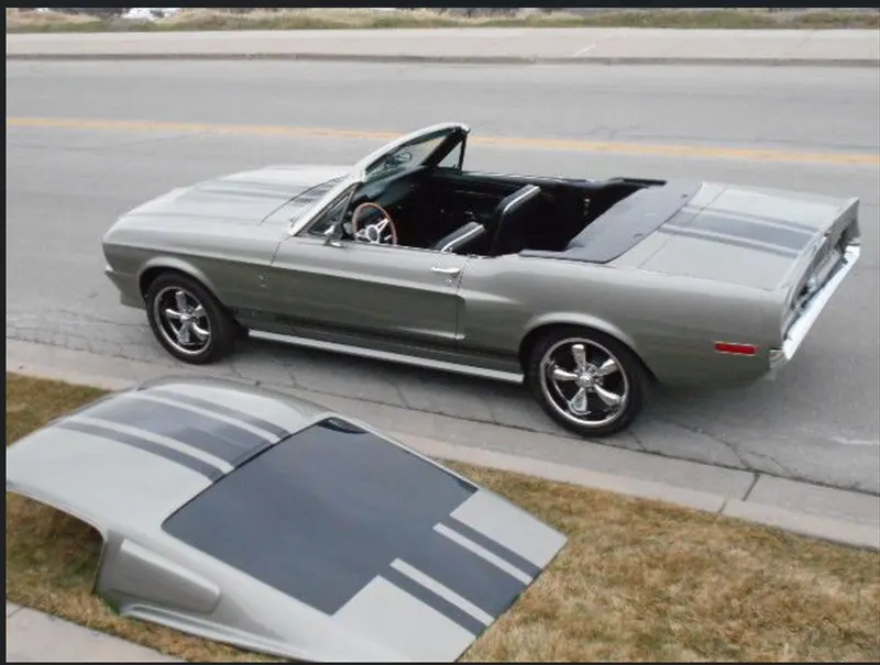
- Retraceable Hardtops: Made from metal or any other composite material and is retracted automatically.
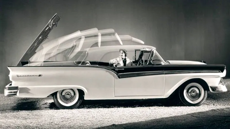
- Soft tops: This type of convertibles has roofs that are not made from metal or plastic. They are made of textile. The earliest versions of the convertible used canvas for the roofs.More recent models use cloth materials instead. Other materials used now includes latex, vinyl, polyvinyl chloride. When the roof is flooded, it is called stack.
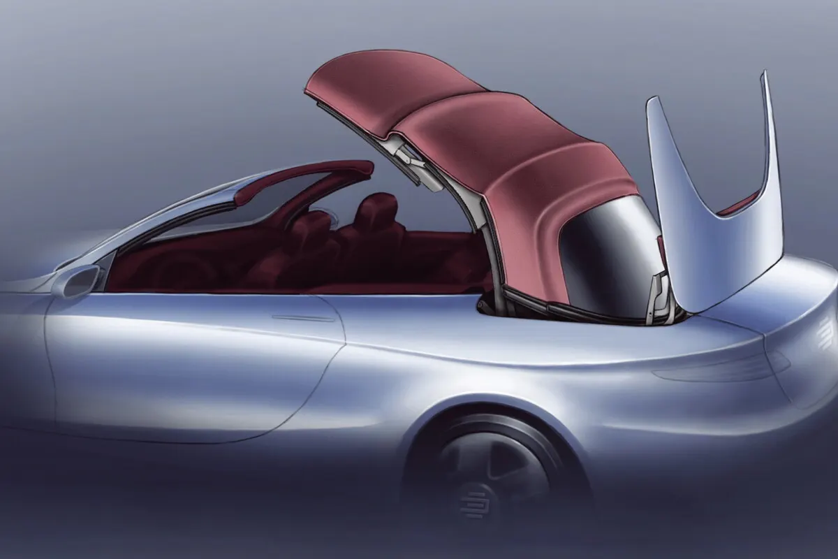
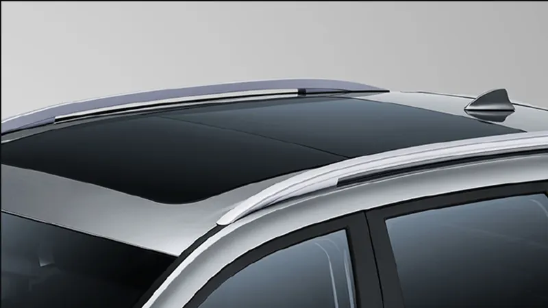
SUNROOF: A sunroof is an operable type of roof that allows for an opening in the roof of an automobile. It can allow either light or air or both to enter the vehicle. They are either operated manually or automatically. The differnt types of such roof is mentioned below.
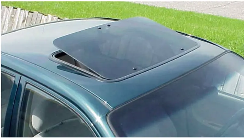
- Pop-up: The pop-up sunroof usually tilts when you open it. It is the most basic and relatively cheaper type of sunroof. Some can even be removed so that they are kept properly.
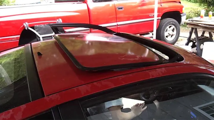
- Spoiler: The spoiler is a pop-up that would slide, instead of tilting upwards. The advantage of this is that it can be restored to its original position by sliding.
- Panaromic: While other sunroofs basically allow air and light or both into the front seats, the panaromic sunroof would allow the same for both the front and rear seats.
DESIGN CRITERIA TO BE FOLLOWED IN ROOF DESIGN
1. Material Selection:
Material selection plays an important part in designing any part. The material is selected keeping in mind the tensile strength, bending moment, dynamic and dead loading subjected to that part. Vehicle roof is subjected to the rollover accidents which are most dangerous among all kind since it directly attack occupant's head and neck.
Mechanical strength, low weight, shock/Energy absorption capability, cost and ease of manufacturing are the important
parameters for material selection for roof.
Steel has very less shock absorbtion capacity and it may transmit shock to the occupant during collision of the roof with the ground. Here plastic with the best supporting material can become the solution as plastics are famous for shock absorption capacity.
2. Visibility Criteria:
The visibility criteria of the occupant or driver is one of the most important factors when designing the roof. The roof should designed in such a manner that it does not obstruct the required visibility range of the driver. The ditch area of the roof is designed keeping in mind the visibility criterion of the roof design.
3. Head Clearance
This factor is considered while designing the reinforcement of the roof. The reinforcement should be designed in such a way that ample amount of head room should be there so that the occupant's head does't collide with the roof rails while the car moves over a bump or speed breaker.
4. Position of the reinforcements
The position of the roof reinforcements are governed by the below metioned criteria
- Heat Distortion: This factor determines the fuctionability and strength of the roof reinforcements under extreme hot weather conditions. The value obtained from the heat distortion prediction formula tells us whether the positioning and dimensions of the roof reinforcements are suitable for high tempratures or not. The value of heat distortion prediction formula should be well below 2.7 for the reinforcements to be considered fit for use.
- Snow Load Criteria: This factor is taken into consideration for area having cold climatic conditions and where snowfall happens for most of the times in cold seasons. The criteria measures the elasticity of the roof wherein the roof should come back to its original shape upon the removal of dead load caused by the heavy snow layered on the roof. The value of Qr obtained for the snow load prediction formula should be greater than 3.1 for the roof reinforcements to get passed in snow load criteria.
- Drawibility: The roof and its parts are manufactured using deep drawing process. For this reason, the designs should be manufacturable and designs should should have a positive draft angle for smooth surface build and also reduced induced stresses in various parts of the reiforcements.
DESIGNING OF ROOF ASSEMBLY:
ROOF OUTER PANEL
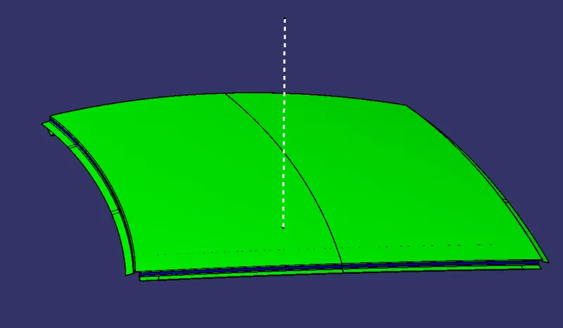
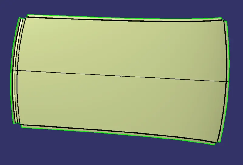
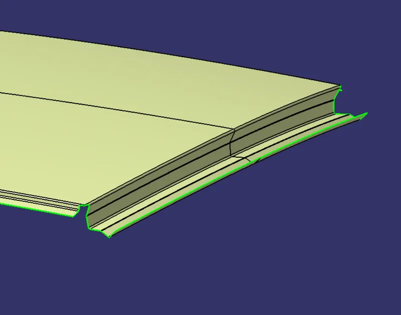
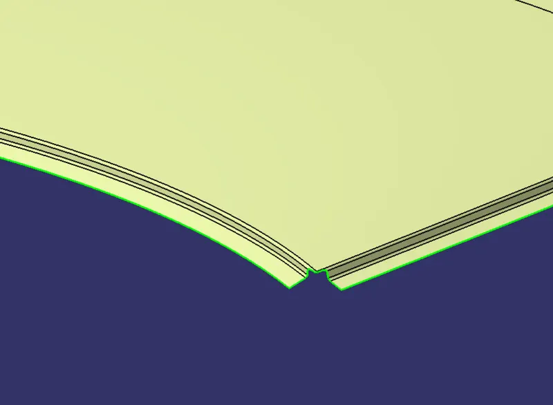
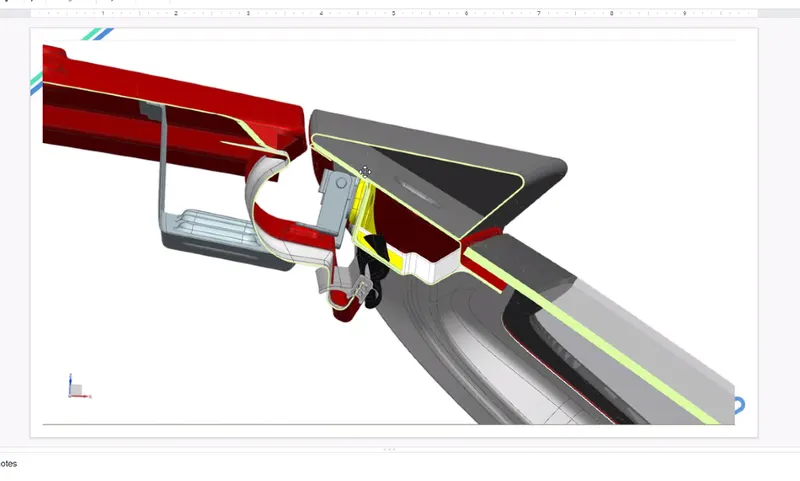
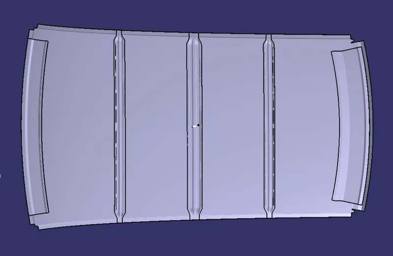
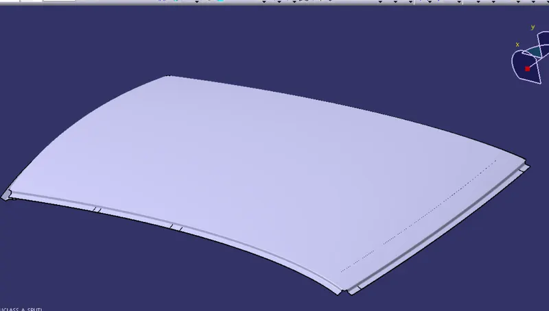
Roof outer panel is designed using the class A surface given to us as an input and the ditch area is created by using the master section data. A corner relief is provided on each corner of the outer roof panel by limiting the flange surface upto some distance well before the endmost corner point.
FRONT ROOF RAIL
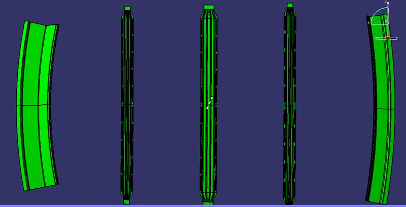
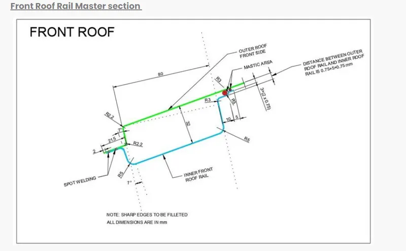
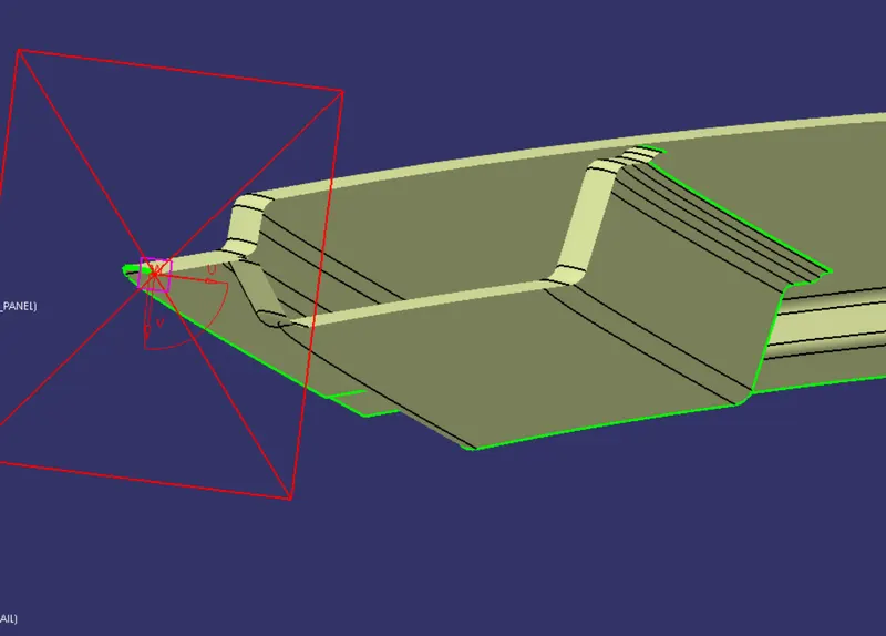
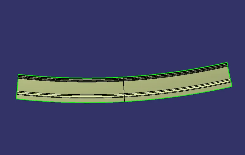
We have the master section data availaible to us for the front roof rail with help of the which we'll take references for the front roof rail design. As we can clearly see there is no gap maintained between the outermost flanges of outer roof panel and front roof rail, this is so because both these surfaces would be spot welded.In the designing process of front roof rail sweep command is used most frequently to develop the flange surfaces and these are inclined w.r.t the tooling axis with the draft value given as per the master section data.
REAR ROOF RAIL
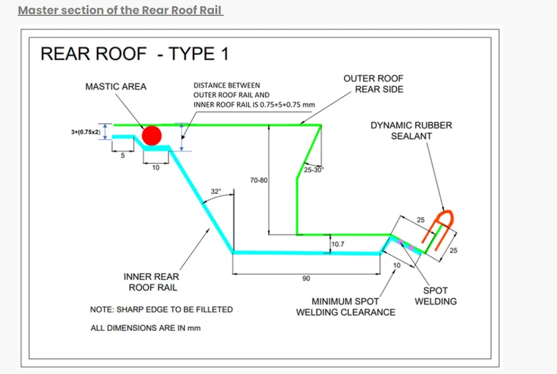
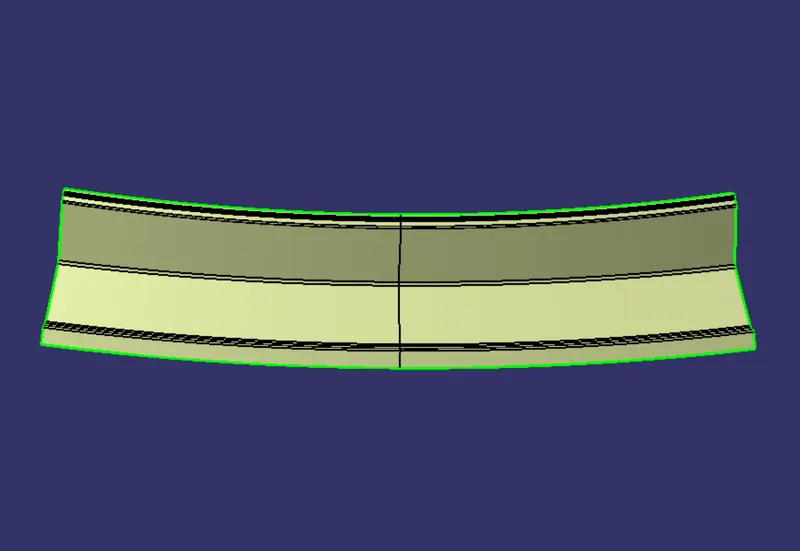
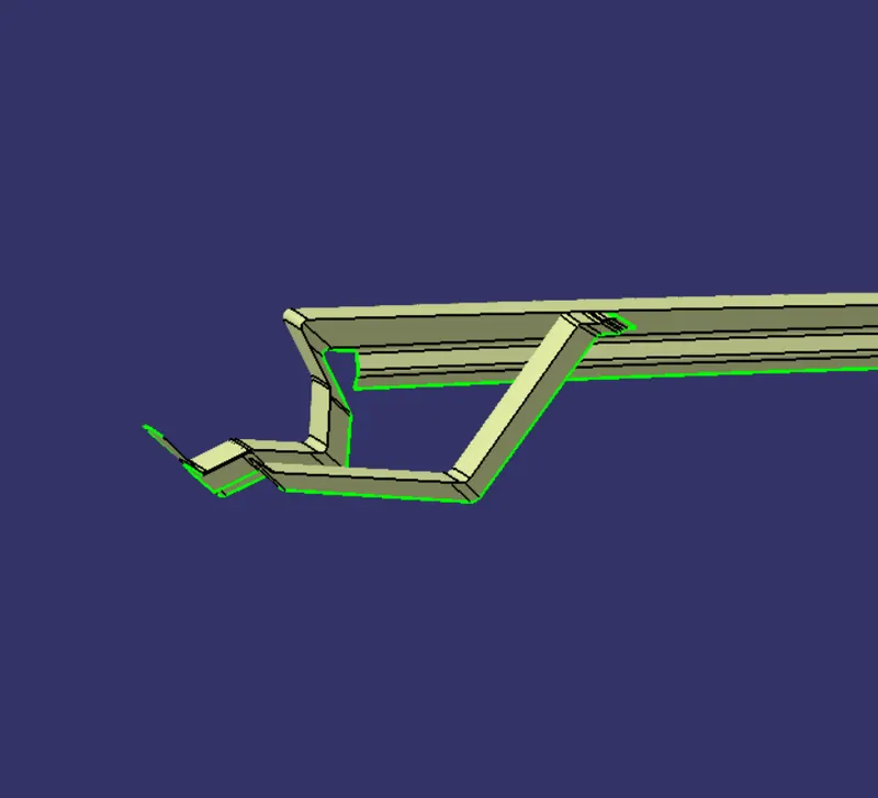
For designing the rear roof we have been given two different types of master section, rear roof type 1 as shown in the pictures below is taken up here in the designing process of rear roof rail. This type of rear roof rail is mostly used in hatchbacks and SUVs. The different thing about this type is that it allows room for the backdoor top edge to move about the hinges without clashing with the roof outer panel.
CENTER ROOF RAIL:
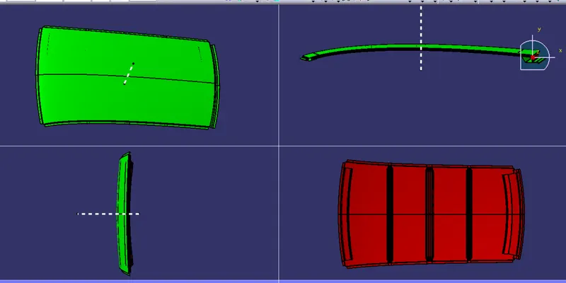
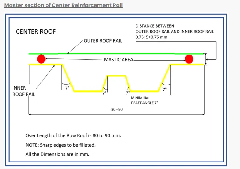
The center roof rail provides the roof with an additional strength in an adverse conditions of car getting roll over and protects the occupants from serious injuries. The center roof rail is always attached to the B-pillar through reinforcements which is done to transmit the impact energy via center roof rail to other sides of the car in case of side collisions.
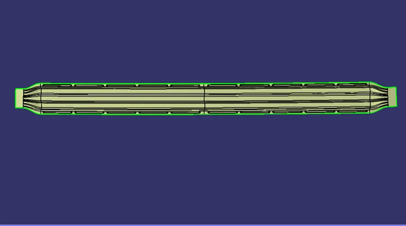
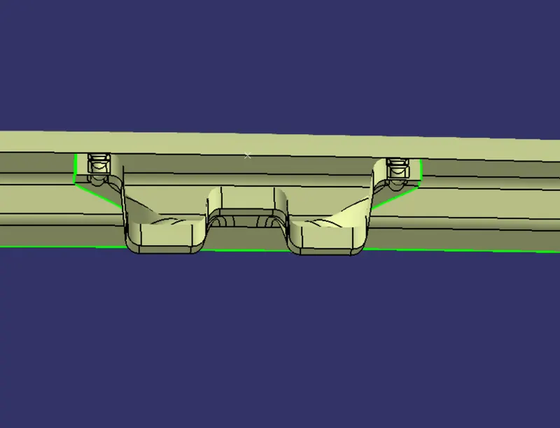
The reinforcement of the rail is attatched with the roof by Mastics sealant and attached to the rail by spot welds. For putting the mastics a clearance of 5mm is maintained between roof and reinforcement.
BOW ROOF RAIL:
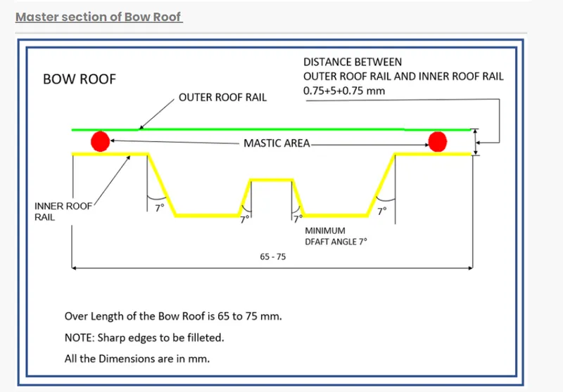
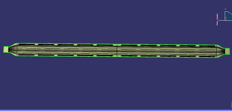
The bow roof rail also provides the roof with structural strength and their position have to be justified by the Heat Distortion and Snow Load Criteria. Both the bow roof rails are attached to the roof by means of Mastics thus a clearance of 5mm from the roof is provided for that purpose.
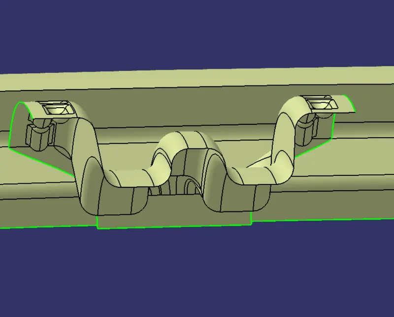
BOW ROOF CALCULATIONS FOR HEAT DISTORTION AND SNOW LOAD CRITERIA:
Bow–Roof Prediction Formula
W = [1.73 x 10^(-3) x L] + [1.85 x 10^(-8) x (R^2)/t] + [ 1.10x10^(-3) x l] - 2.68
Where,
L = Roof Length in X-Direction[mm](Roof dimension in 0-Y)
R = Roof curvature
R = 2(Rx*Ry)/(Rx+Ry)
Rx = X curvature
Ry = Y curvature
t = Roof plate thickness [mm]
l = Bow Roof Span [mm]
Judgment Condition
OK< 2.7
PRE MEASUREMENT PROCESSES:
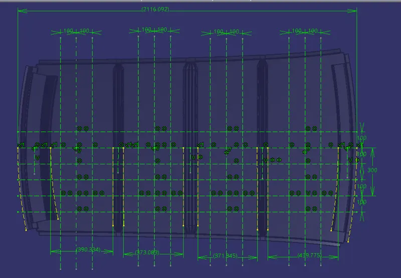
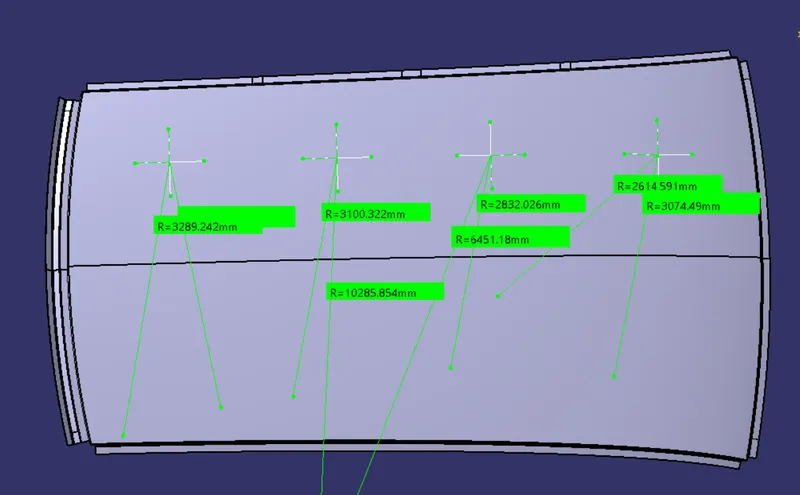
In order to obtain the above mentioned details we'll create the sketch as shown in picture below. Here we have made some points at the intersections of the horizontal and vertical construction lines and each lines is separated from the other with a distance value of 100mm.
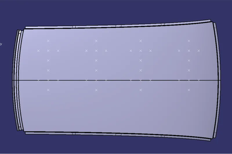
After the completion of the sketch we'll project the sketch on the outer roof panel and so that we could obtain the required points on the outer roof panel surface.
Join all the points on the outer roof panel surface with curves and make the roof panel as their support we'll obtain the curves as shown in the picture below.
MEASUREMENT OF Rx AND Ry VALUES:
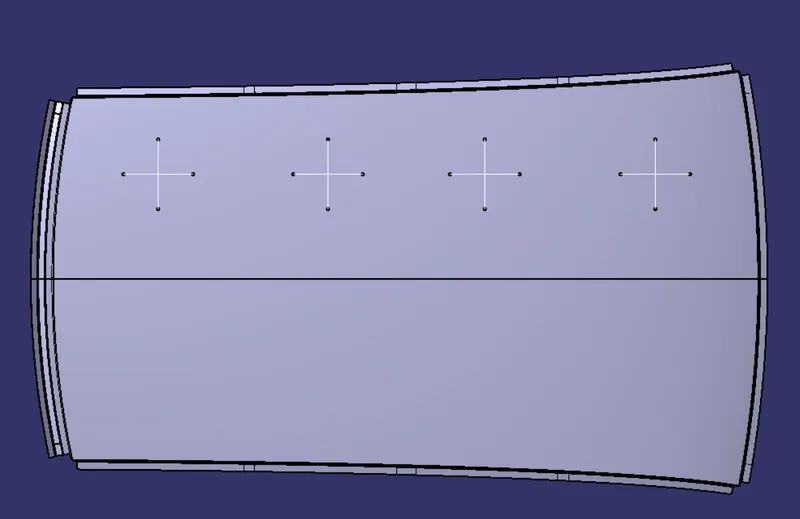
Calculate the the radius values of the curves with the help of measure tool, the radius value of the horizontal and vertical curves are nothing but the Rx and Ry values required in the bow-roof prediction formula.
RESULTS:
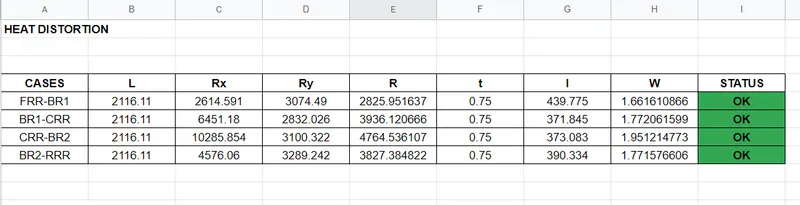
As shown in the above sheet data we can clearly say that our bow-roof design is completly feasible in terms of heat distortion.
Snow Load Prediction Formula
Qr = [Iy x t2] / [α x s x [(Rx + Ry)/2]2 x 10-8]
Note: The Qr value given over here is correct. There was a typo error in the formula given in the video.
Where,
α = My x Lx2 x 10-12 , My = Y(Ly-Y)
t = Roof plate thickness [mm]
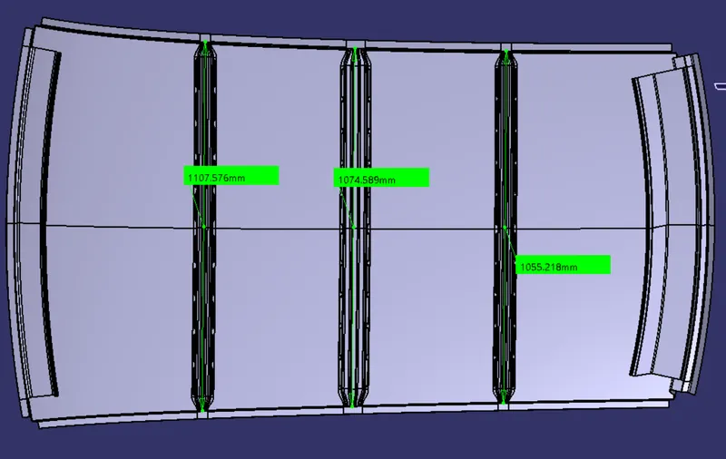
Ly = Distance between the front and rear roof Rails on the Vehicle along with 0Y[mm]
Length of Roof panel with the center point between Roof rail Front /Rear as the front and rear reference point.
Lx = Distance between the Left and Right end of the roof on the Roof BOW [mm]
The width of the roof panel is exposed on the surface.
Y = Distance front Front Roof Rail to Roof BOW[mm]
s = Distance for which Roof BOW bears divided load [mm]
s = L1/2 + L2/2
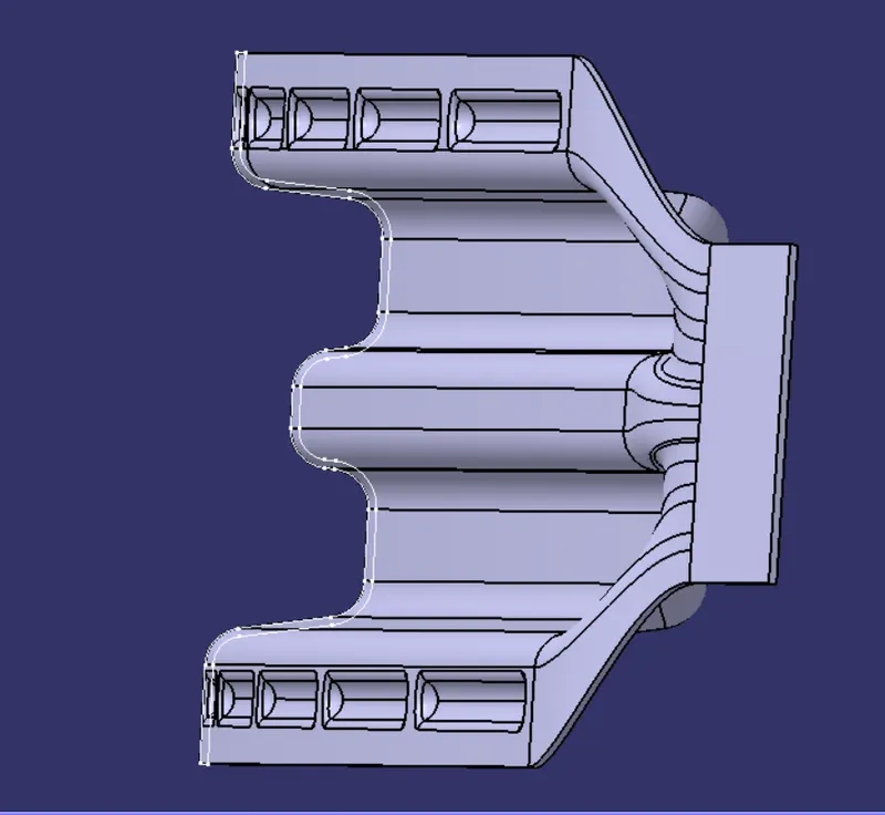
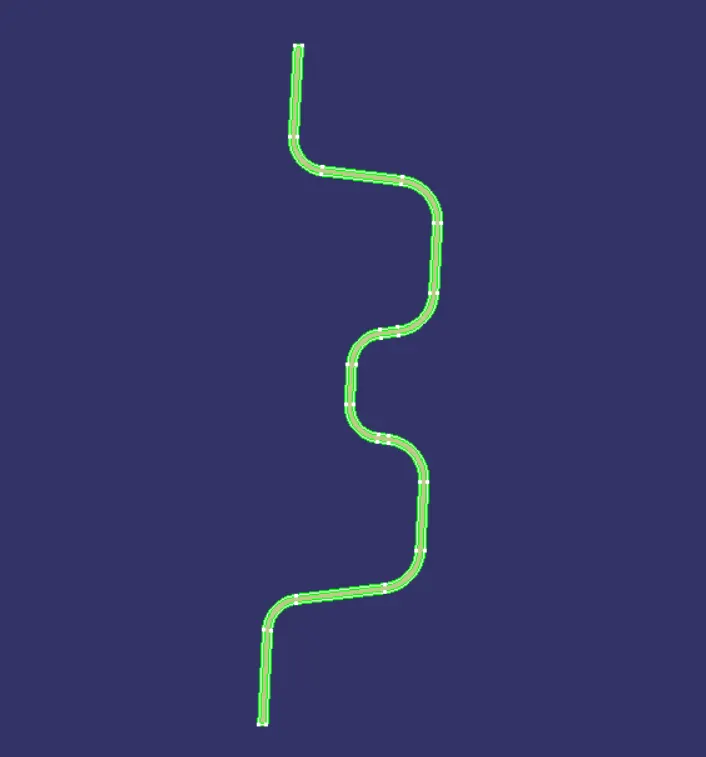
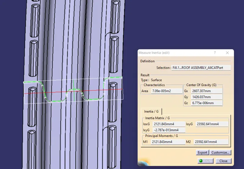
Iy = Geometrical moment of inertia of Roof BOW (Y cross-section )[mm4]
Rx = Lateral direction curvature radius of roof panel Y cross-section on Roof BOW [mm]
Roof panel curvature Radius of the Length Lx in Front view
Ry = Longitudinal Direction curvature radius of the Roof panel X cross-section on Roof BOW [mm]
Roof panel X curvature radius of length s in Side view
Judgment condition
Qr ≥ 3.1
PRE MEASUREMENT PROCESSES:
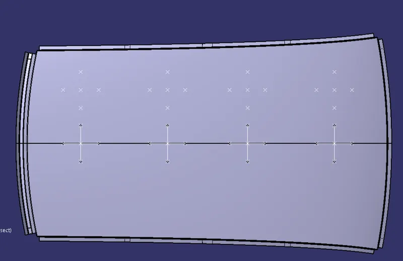
MEASUREMENT OF Rx AND Ry VALUES:
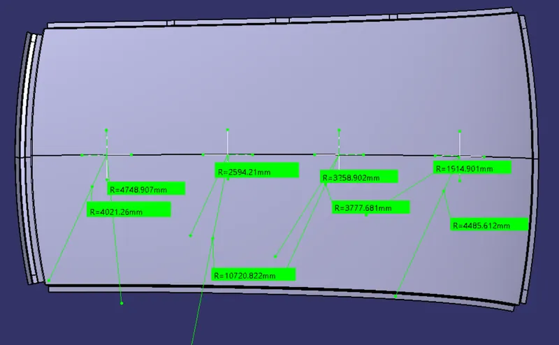
AREA MOMENT OF INERTIA CALCULATIONS:
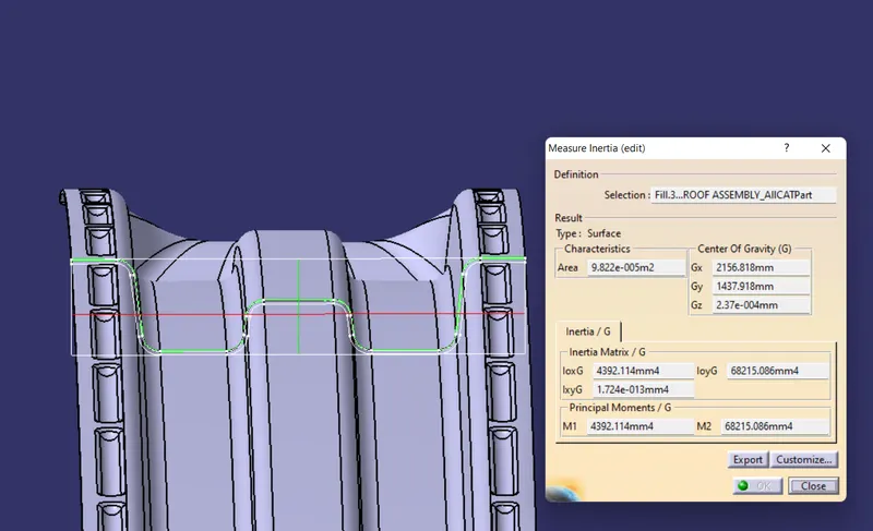
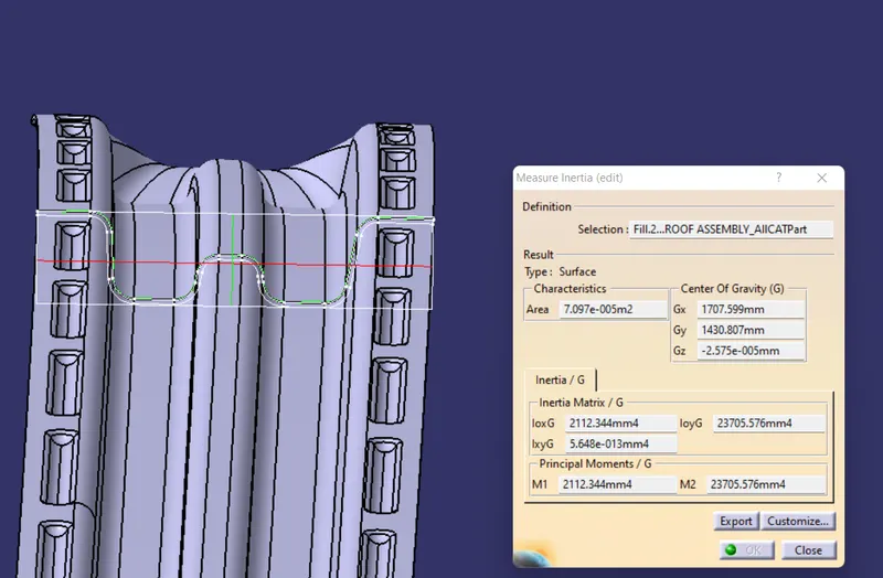
RESULTS OF SNOW LOAD CALCULATIONS:
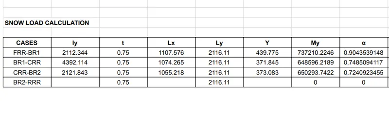
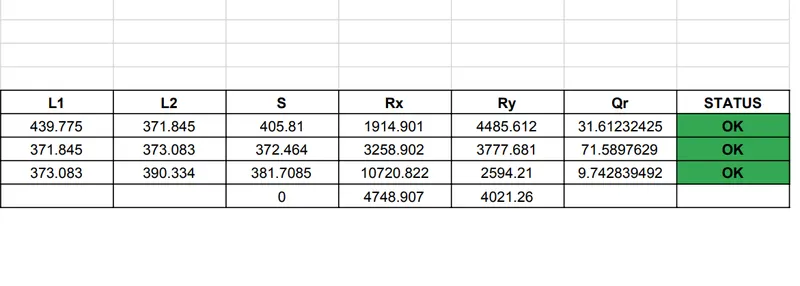
CONCLUSION: From the above shown results we can conclude that the positioning and parameters of the bow roof rails are optimum for the snow load criteria.
THICKENED PART MODEL:
DRAFT ANALYSIS: