Hood design-Week 2
DESIGNING OF THE HOOD ASSEMBLY
OBJECTIVE:
- To design hood outer panel and hood inner panel using the class A surface and the master section of the hood assembly as an input.
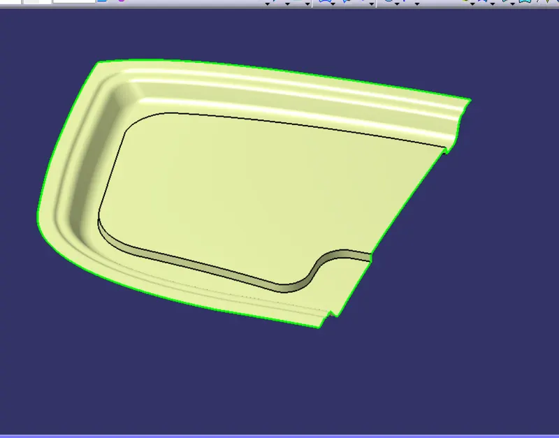
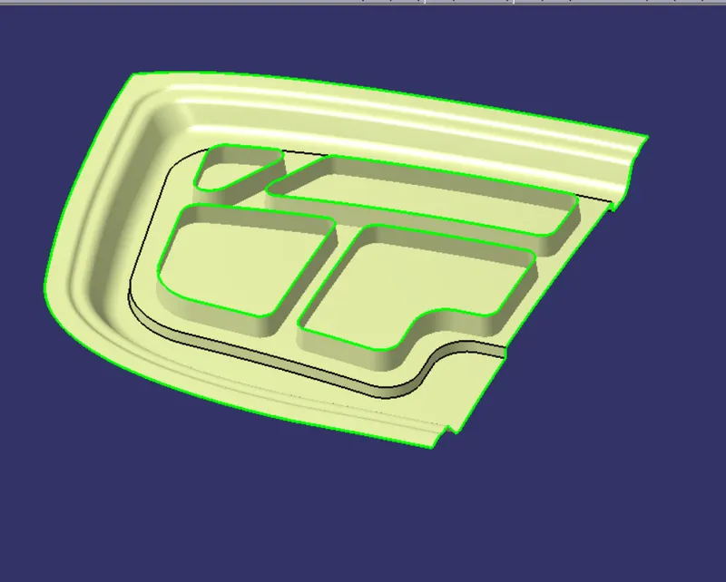
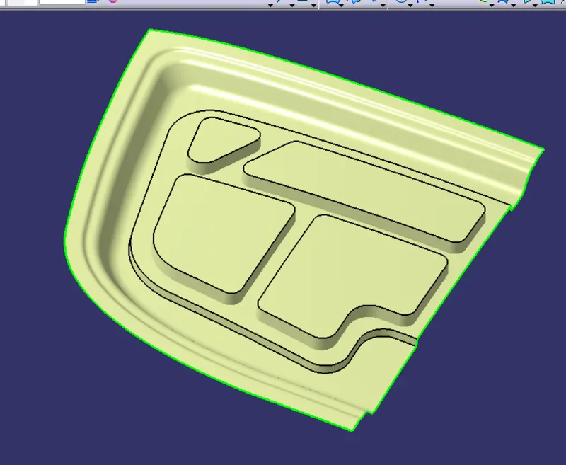
- To create embosses and maestic sealant points on the hood inner panel.
- To assemble all the constituent parts of hood assembly i.e. hood outer panel, hood inner panel, hinges and latch(striker) by applying appropriate constraints.
INTRODUCTION:
HOOD:
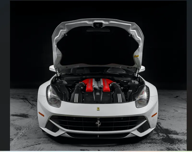
A hood also known as bonnet is a hinged cover that rests over the engine or covers the engine compartment from the top. It serves several purposes, such as to access the engine compartment in cases where one needs to repair, replace or maintain any of the components lying in the engine compartment.
It also serves a great deal of purpose in pedestrian safety, it reduces the impact of collision by absorbing the a significant amout of energy produced during collision.It also prevents the pedestrian from geting directly hitted by the engine frame or body.
Hood design plays a major role in the attractiveness of a car since a major part of the front aesthetics of a car is covered by the hood. It also restricts the noise comming out of the engine compartment to some extent.
PEDESTRIAN SAFETY COMPLAINCE IN HOOD DESIGN
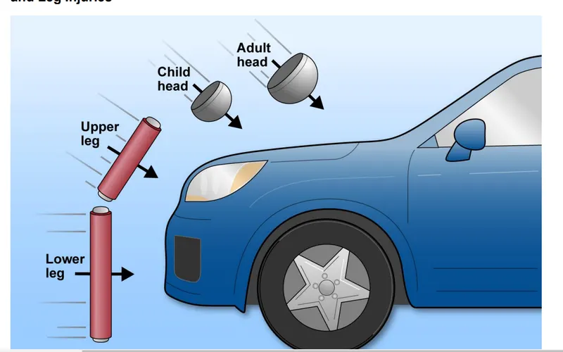
- Since many pedestrian crashes involve a forward-moving vehicle. In such a crash, a pedestrian is impacted twice, first by the car and then by the ground. But a majority of fatal injuries often happen due to the traumatic interaction with the car.
- In an unfortunate scenario of an accident, the vehicle bumper first hits the lower limbs of the pedestrian, the leading edge of the hood hits the upper thigh or pelvis, and the head and upper torso are struck by the top surface of the hood and/or windshield. Therefore manufacturers around the globe have incorporated key changes in vehicle design to avert fatal accidents.
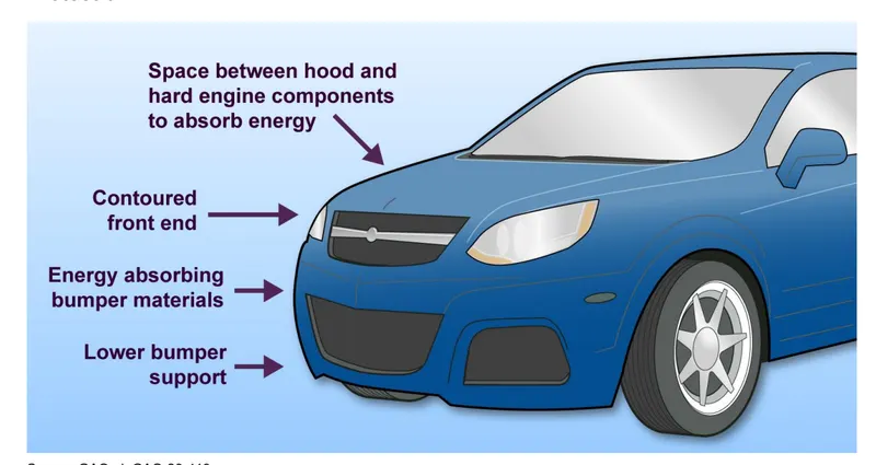
- The hood in a majority of vehicles is generally fabricated from sheet metal, which is capable of absorbing energy posing a comparatively lesser threat.
- However, most fatal head injuries occur when there isn’t a sufficient clearance between the hood sheet and the underlying engine components.
- By creating a gap of approximately 10 cm pedestrian’s head can achieve a controlled deceleration and a reduced risk of death.
- But creating this room is a challenging task because there are other design constraints, such as aerodynamics and styling.
- Thus engineers attempt to overcome this problem by using deformable mounts, and by developing more ambitious solutions such as airbags that cover the stiff regions of the hood when activate.
HIC (Head Injury Criterion): A numbered value that indicates the degree of damage inflicted on a head impactor.
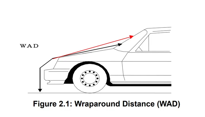
Wraparound Distance (WAD): The shortest line of the lines that connects the reference plane with any point on the vehicle, which passes through the vehicle's front and front's upper-surface within the vertical plane that includes the vehicle's fore-aft axis.
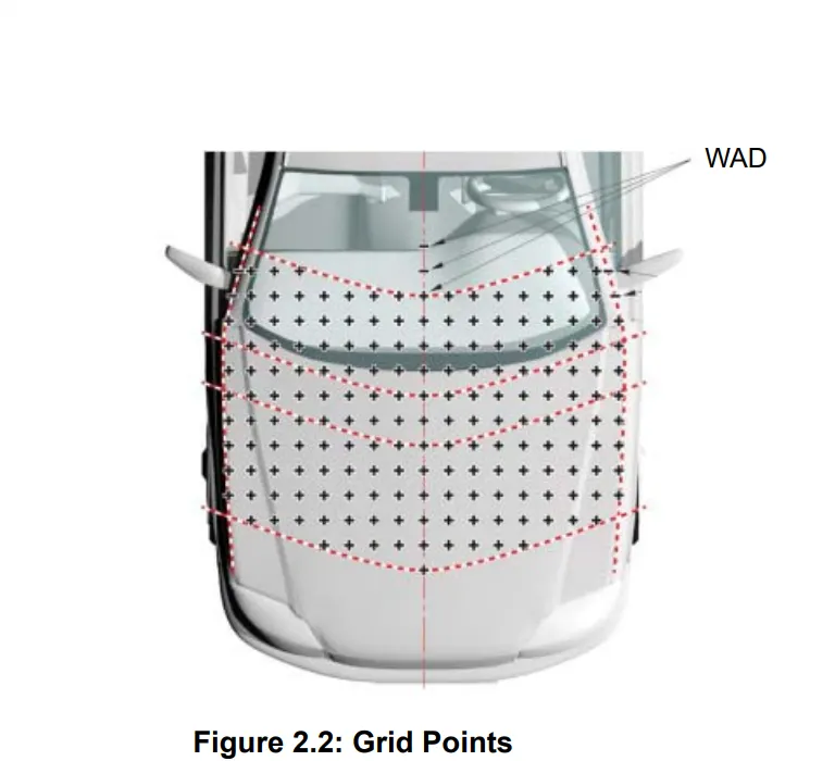
Grid Points: Indicates the point of intersection of the lines made by a 100mm pitch from the WAD1000 in the lateral direction or fore-aft direction above the vehicle's center line.
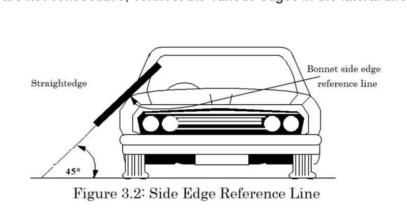
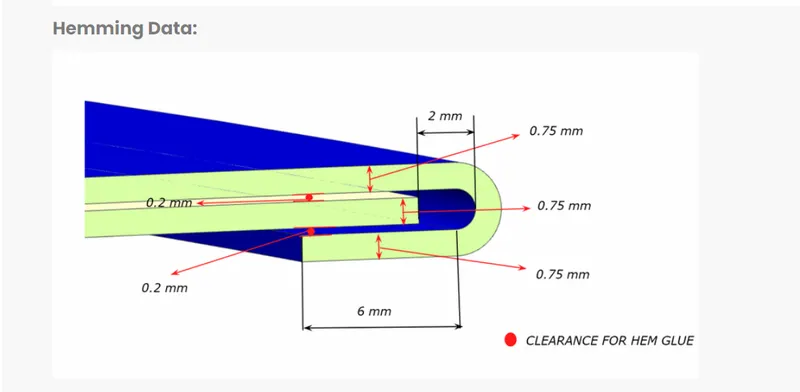
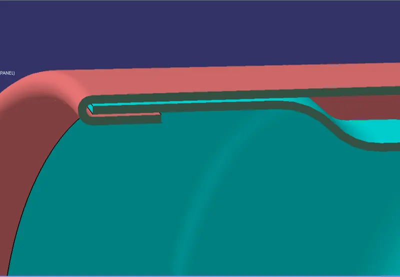
HEMMING:Hemming is the process of joining both the outer and inner panel together. The hemming process roles and wraps the hood outer panel around the inner panel and holds it tightly together.
HEMMING DATA:
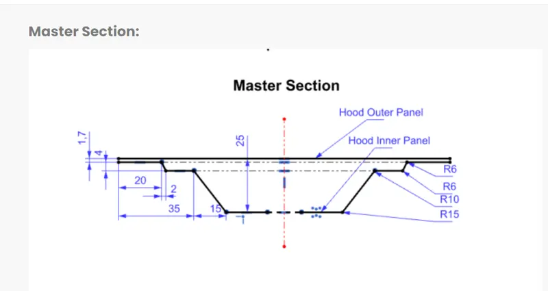
MASTER SECTION: Master sections development takes place during feasibility check and concept validation stages of the product life cycle. These are typically the guides for design requirements and which decides the component packaging after the development of the concept design, i.e class A surfaces.
Master section helps us to decide the feasibility of the concept design, the clearances, the packaging and the fixation strategy of a component before converting the concept design into a solid 3D engineering design.
During the period of vehicle concept design the evaluation of the master section performance depends mainly on the reference vehicle data and experience of structure design engineer.
MASTER SECTION DATA:
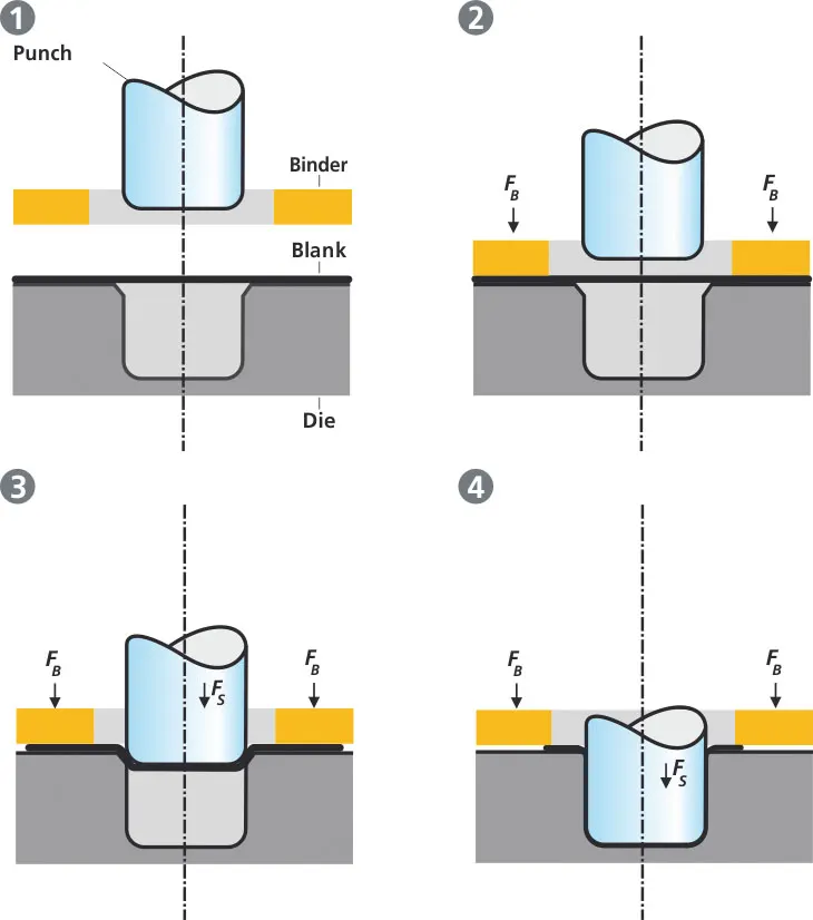
DEEP DRAWING: Deep drawing is the forming process which is often used in automotive industry to create car monocoque panels and other car body parts. In this process the sheetmetal or the workpiece experiences a combination of compressive and tensile forces.
The setup involved in the deep drawing process consists of a die having a cavity shaped according to the emboss that we want to create on the workpiece, and there is plunger or punch with the same shape as that of the cavity but having some clearance between them.
The sheet is clamped between the die and the binder, this process slows down the flow of the sheet while it is being drawn and thereby prevents the formation of wrinkels from forming under the binder. The plunger stretches the sheet over the die radius and forms it in the die. The amount of punch force necessary for forming thereby continually increased upto to the lower dead center of the punch.
Whereas in pure deep drawing process there is no reduction of sheet metal thickness, forming is achived in stretch forming purely as a result of decrease in sheet metal thickness.
DESIGNING METHODOLOGY:
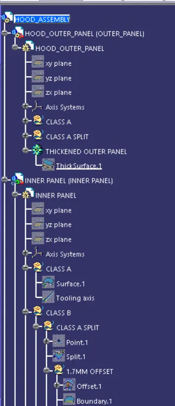
OUTER PANEL DESIGN USING MASTER SECTION
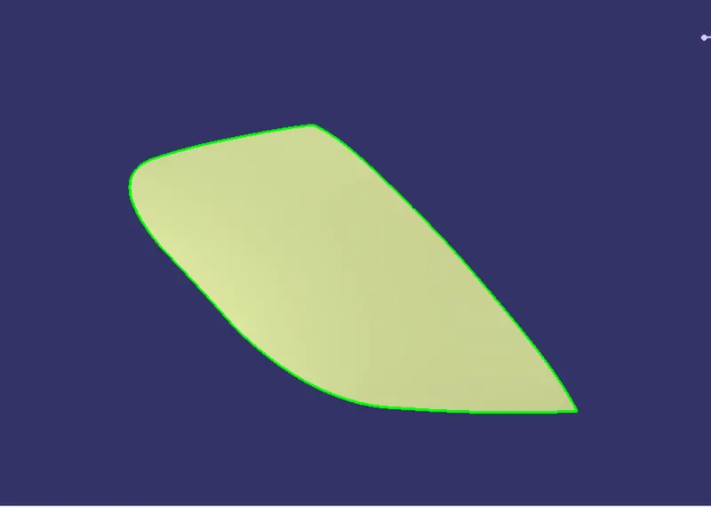
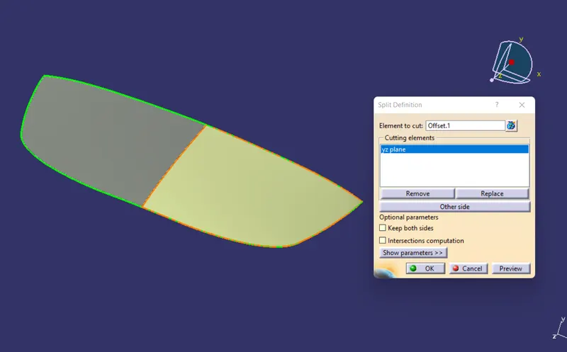
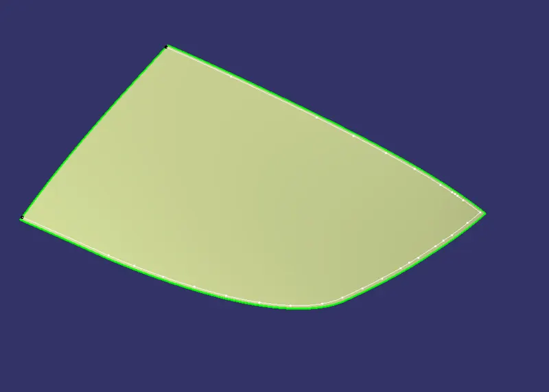
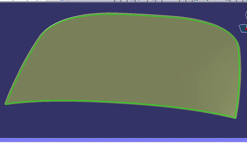
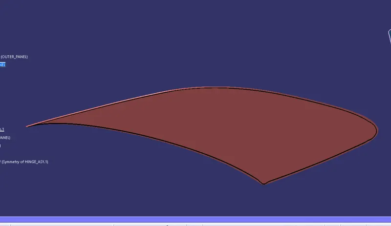
- Since we are dealing with a model which is laterally symmetric so here we need not design the inner panel completly, what we can do is just split the Class A surface into exactly half portion and then work on it.
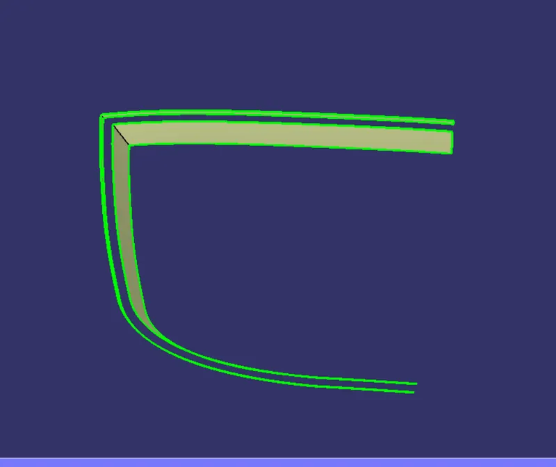
- To create the hemming portion first we'll offset the class A split with an offset value of 2.5mm as shown in hemming data.
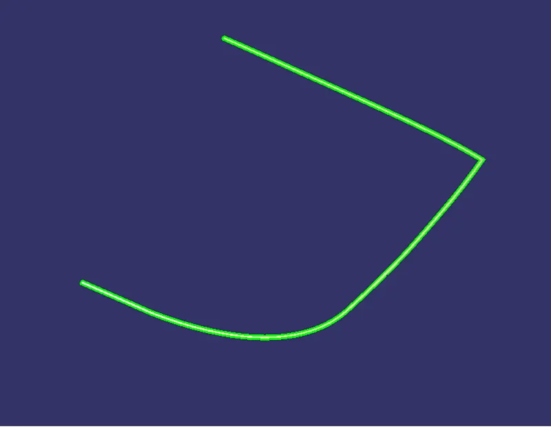
- Create boundary curve to the offseted surface by using boundary command and make sure that boundary curve is not applied on the edge along which the surface was being splitted initially.
- Create parallel curve using the above created boundary and make support as the offseted surface and as per the hemming data make the constant value of 6mm.
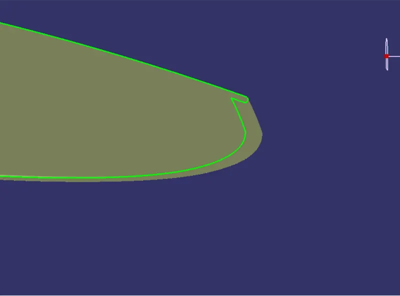
- Now split the surface using the parallel curve as cutting tool the resulting strip formed will be the folded portion of the hemmed surface.
- To create the curved portion of the hemmed surface use either blend surface command or tritangent fillet command.
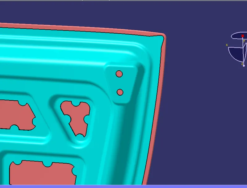
- Provide corner relief by spliting off the hemmed surface and maintaining a margin of 3mm at the corner. Providing corner relief is required in order to preven overlaping of the hemmed portion at the corners and that can lead to tear of the sheet from the corners.
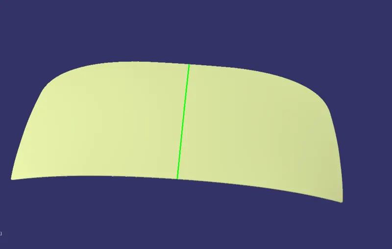
- Once we are done with all the details related to outer panel surface, we'll mirror the exsting half portion along the same plane through which we splitted the class A initially and we'll get the other half, we'll join both the haves together to form the complete outer panel surface.
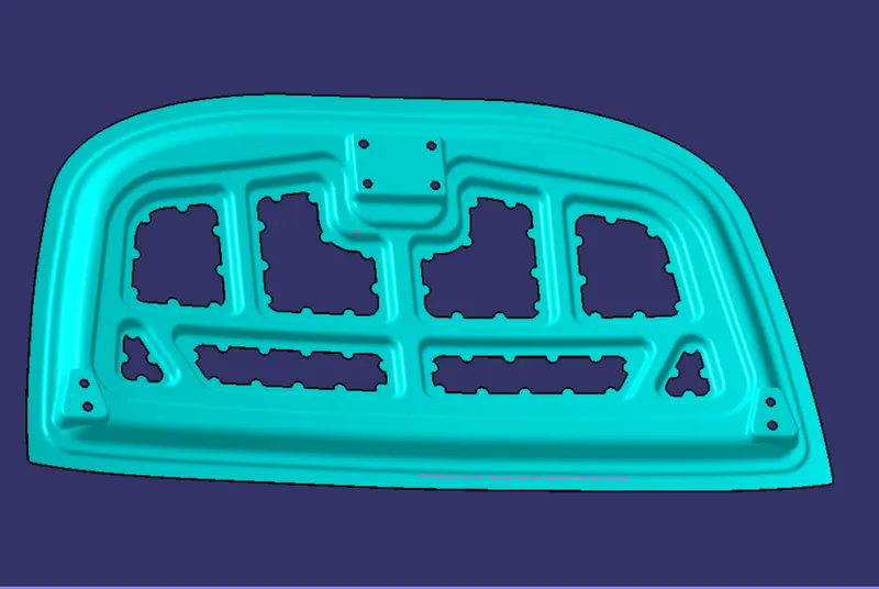
- Finally use the thicken command to provide thickness to the resulting outer panel surface with thicknening value of 0.75mm.

INNER PANEL:
INNER PANEL DESIGN USING MASTER SECTION
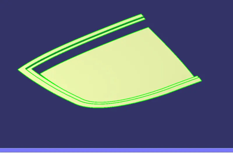
- Since we are dealing with a model which is laterally symmetric so here we need not design the inner panel completly, what we can do is just split the Class A surface into exactly half portion and then work on it, after we are done completing half of the model we can mirror this half portion with reference to the lateral axis or plane and that would give us the other half of our model and we can finally join them to get the complete model.
- As given in the master section data we can clearly see that the inner panel surface is 1.7mm apart from the class A surface.
- Hence we will create an offset surface with an offset value of 1.7mm from the class A surface using the offset command in GSD workbench.
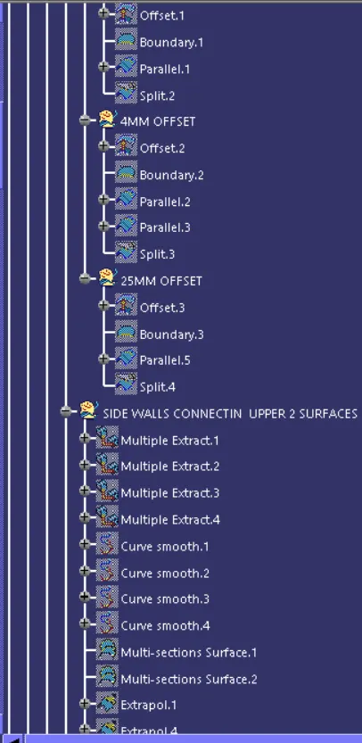
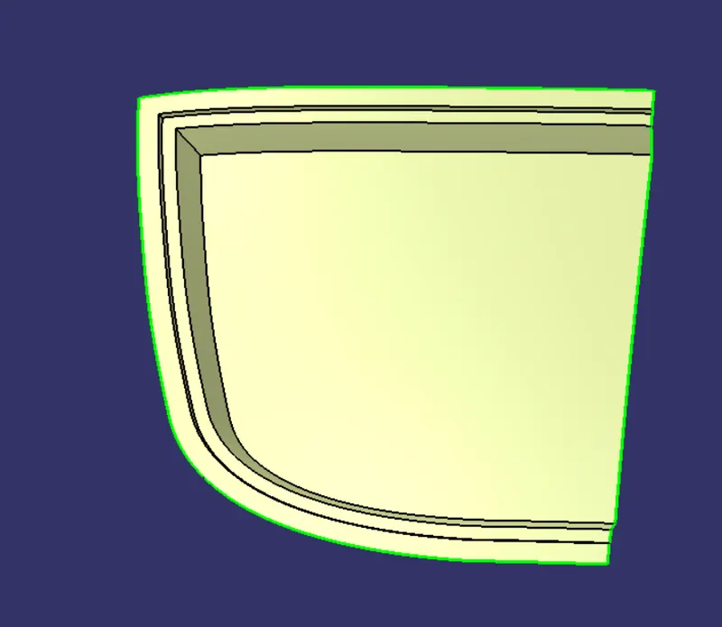
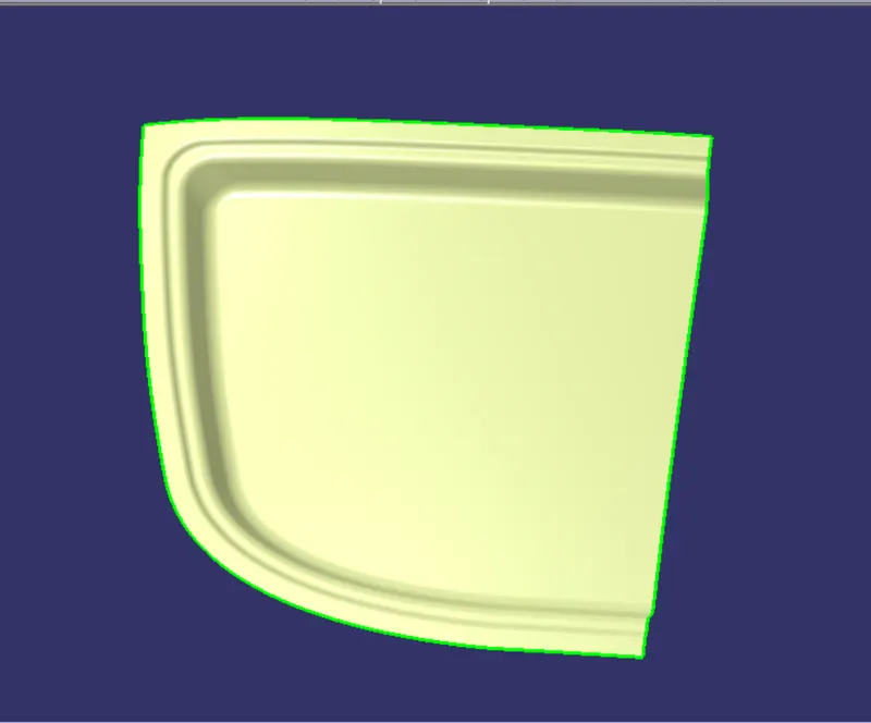
- It is clearly seen from the master section that there are two levels of steps drawn into the innerpanel sheet through deep drawing process. Likewise we'll offset the top surface of the inner panel with the respective offset values of 4mm and 25mm.
- The first step and second step is starting with a depth of 20mm and 50mm respectively therefore we'll use the parallel boundary command to create curves parallel to the main boundary with given depth values and then we'll split the lower two offset surfaces with their respective parallel curves.
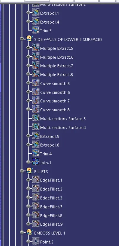
- Then we'll try to connect these three layers of surfaces by creating connecting surface between them, these connecting surfaces can be created by using the multisection surface command.
- Join all the surfaces along with connecting surfaces using join command and apply fillet according the values given in the master section.
EMBOSSING
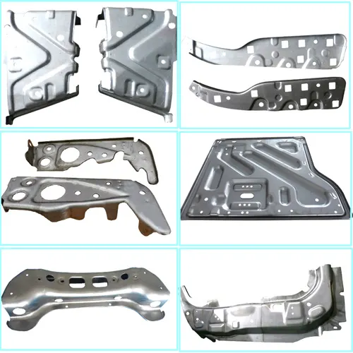
Embossing is a metal stamping process for producing raised or sunken designs or reliefs either by passing metal sheet or strip between rolls of the desired pattern or drawing them using die and plunger mechanism. Embossing is done to add stifness to the hood inner panel.
EMBOSS CREATION
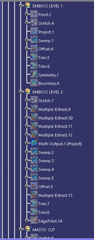
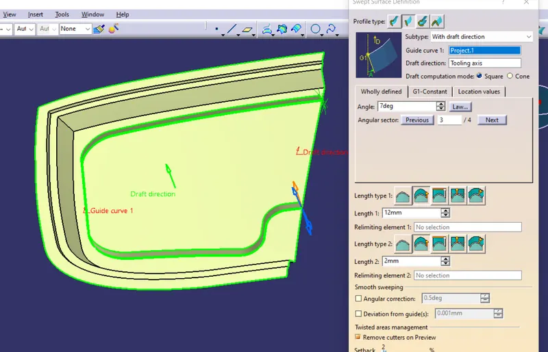
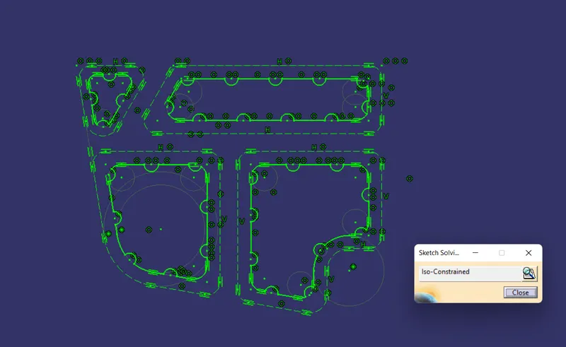
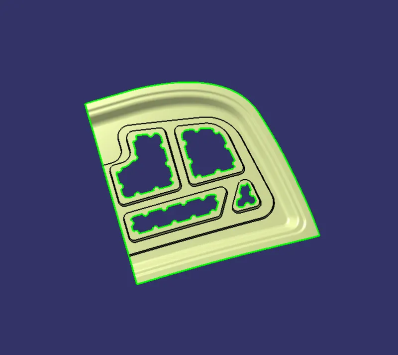
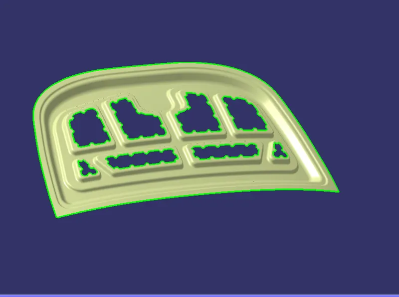
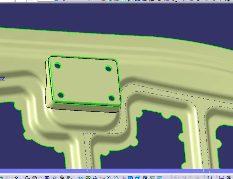
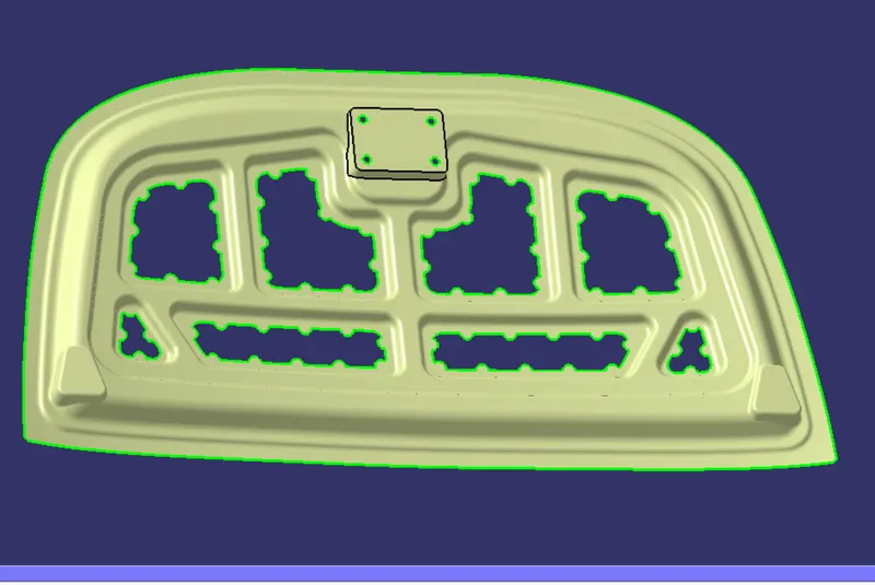
- For creating the first level embosses we'll first create sketches representing the emboss profile and then we'll project these sketches on the inner panel.
- provide offset to the inner panel with an offset value of 10mm(height of the embosses) after that sweep the projected profile along the tooling axis with a draft direction of 7deg. Finally trim the surfaces altogether the resulting trim will be the first level of embossing.
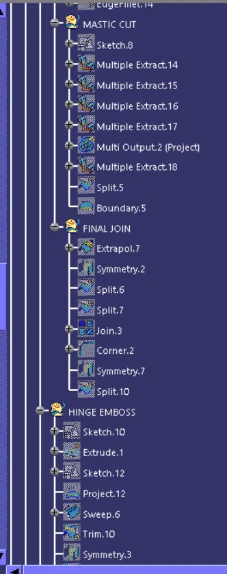
- In similar manner we'll create the second level of embosses but the additional thing that we'll do here is to create a cut out on them with maestic sealant points. For that we'll create and additional sketch representing the offset cut out with maestic sealant points along the cut out profile.
- Make sure that the dia for maestic sealant semicircles should be not less than 7.5mm and there should'nt be a gap less than 50mm between any two meastic sealant points.
HINGE EMBOSS:
LATCH EMBOSS:
THICKENED PART:
CORNER RELIEF:
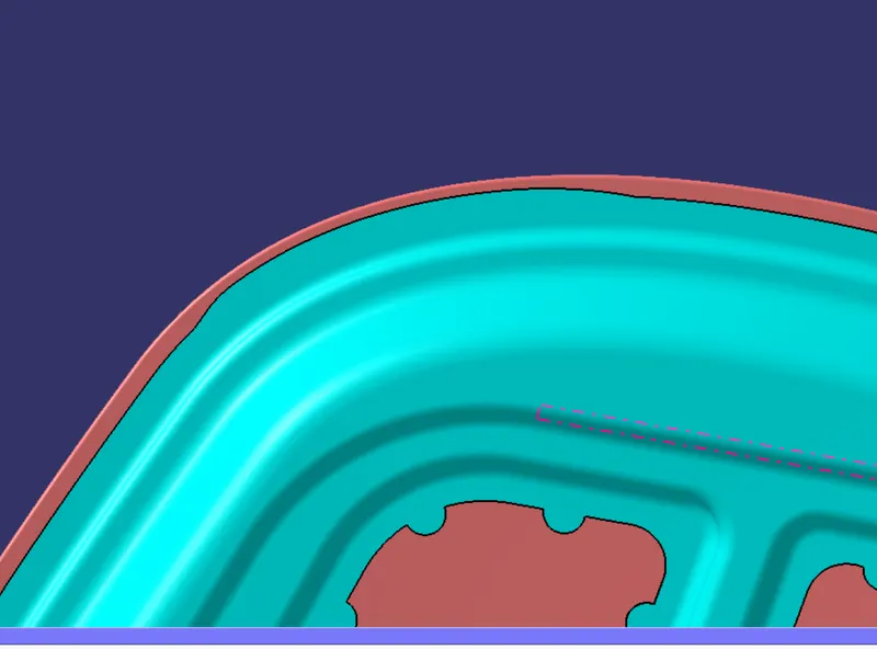
HEMMING PROFILE:
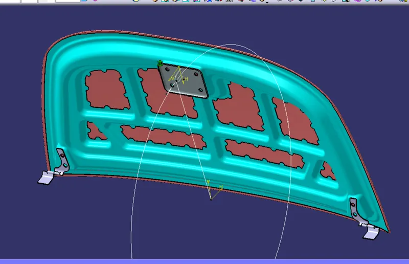
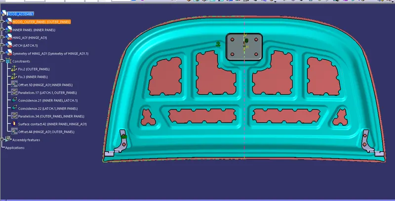
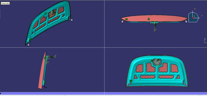
ASSEMBLING THE CONSTIUTENT PARTS IN ASSEMBLY WORKBENCH
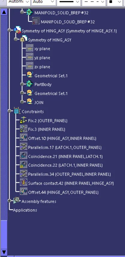
- For positioning the elments the first thing we'll do is to apply fixed constraint to the hood outer and inner panel, the reason behind this is to position the other parts of the assembly i.e hinges and latch with respect to the hood panels.
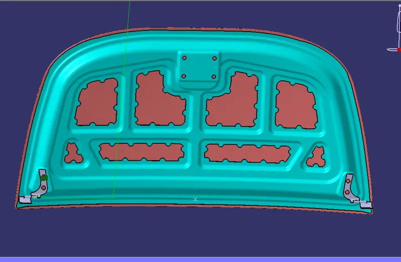
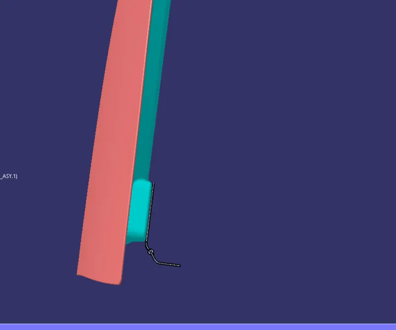
- For positioning the hinges we'll first create a point at the centre of the hinge hole and then we'll create a line along the axis of rotation of hinge.
- Apply various assembly constraints to fix the position of hinges and latch and also to arrest all of their degrees of from.
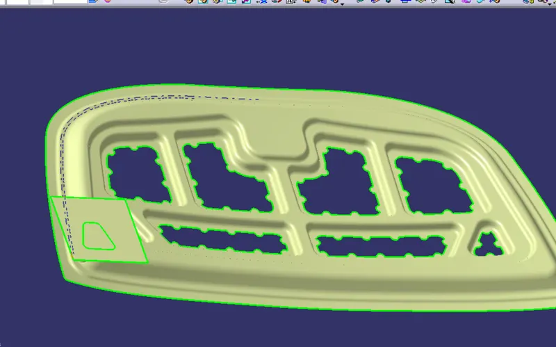
- For example we can give contact constraint between the hinge and and inner panel to place the hinge on the hinge emboss created on the inner panel.
- Once we fix the position of hinge to its exact location we can simply use the symmetry command to create hinge to the other side of the panel with same contraints as that of the first hinge and with exact location.
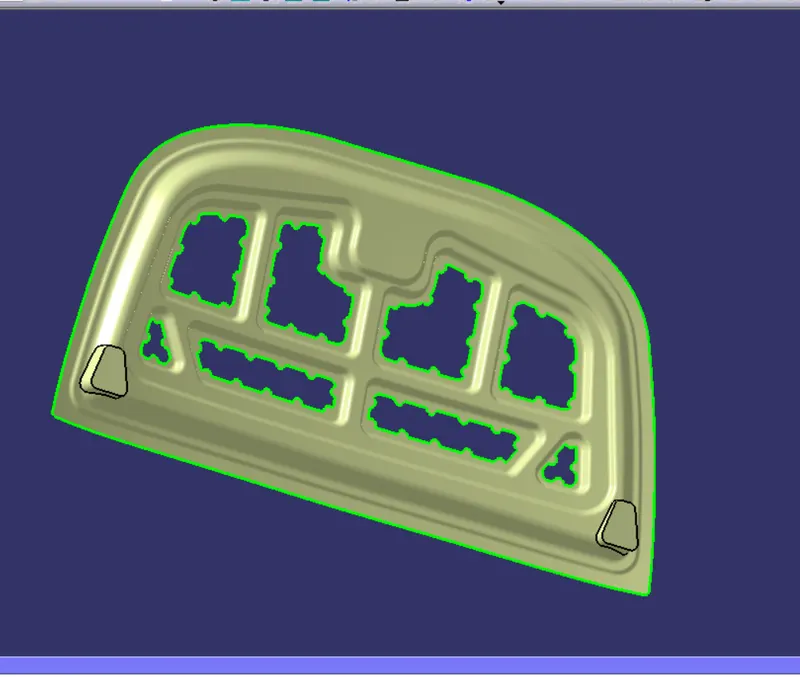
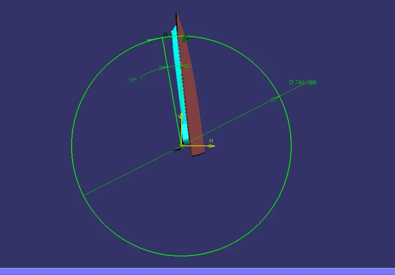
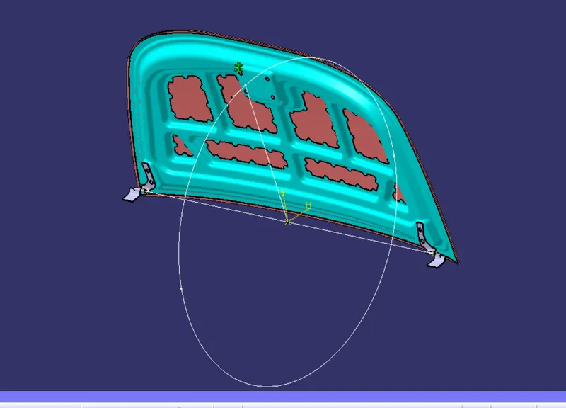
- For positioning the Latch we need to consider the circular motion of the latch about the hinge axis to make accurate inclination of the latch from the inner panel, and accordingly we'll place the latch before the inner panel so that the latch or striker would sit exactly on its position while closing the hood.
FIXINIG INNER AND OUTER HOOD PANEL
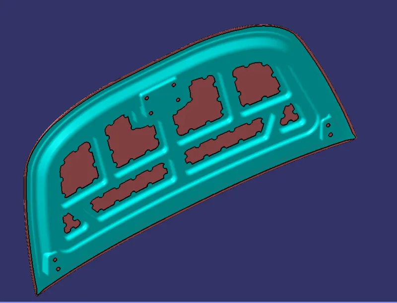
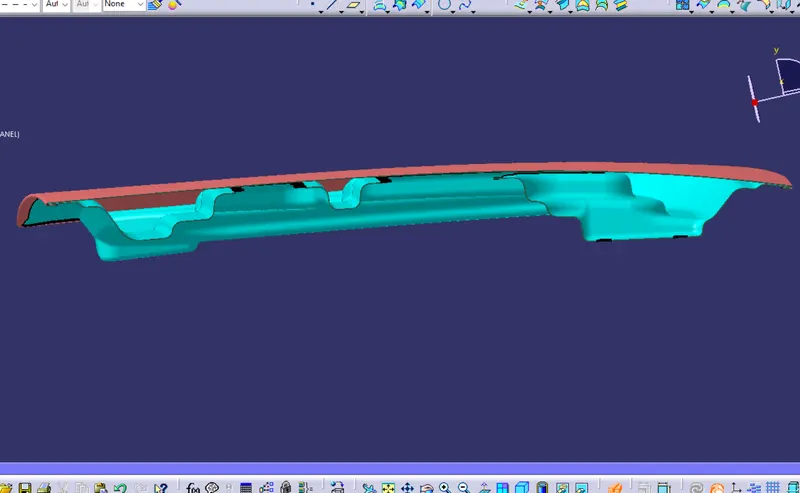
HINGE PLACEMENT:
LATCH TRAJECTORY:
LATCH POSITIONING:
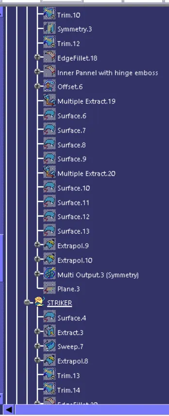
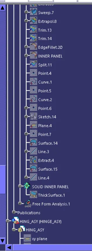
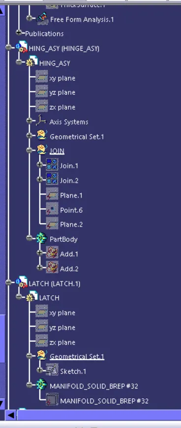
FEATURE TREE: