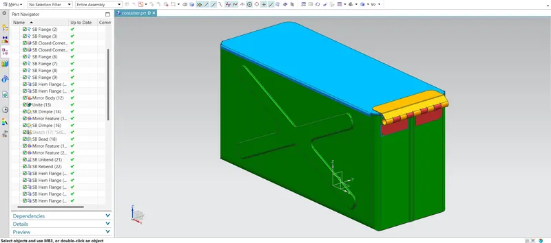
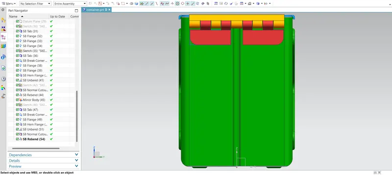
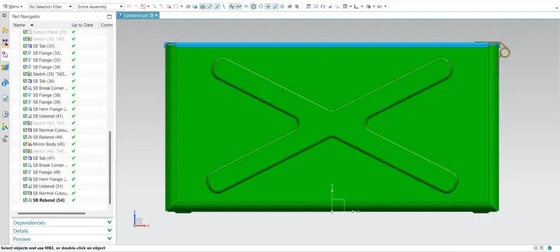
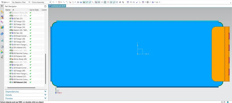
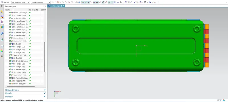
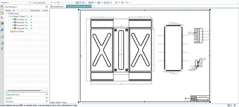
Advanced Sheet Metal Design Using NX Cad Challenge_2_Box Assembly
AIM: Advanced Sheet Metal Design Using NX CAD Challenge_2_Box Assembly.
OBJECTIVE: To design a Box Assembly using SIEMENS NX SHEETMETAL application.
INTRODUCTION:
Sheet Metal is basically a sheet made out of metal like steel through a forming process called rolling and the thickness of sheetmetal starts from 0.5mm and goes upto 6mm. Sheet metal is one of major input material used in automotive manufacturing industries and several other industries. These sheets are transformed into useful products like BiW frames in automotive industry with the help of various sheet metal operations like bending, punching, blanking, piercing, lancing etc.
Applications: Aircraft bodies, Automobiles bodies, Utensiles used for domestic purpose, Bevarage Cans.
The NX Sheet Metal application provides an environment for the design of sheet metal parts used in Machinery, Automotive, Aerospace etc. Enclosures, brackets and other parts normally manufactured with a brake press.
NX sheet metal application provides a set of tools that allows for easy and fast design of sheet metal parts such as BiW components. NX sheet metal design application incorporates features or commands which are very handy for depicting or representing majority of the mechanical operations involved in sheet metal part formation.
some of the examples of such features are: bends, flanges, tabs, cutouts, beads, dimples, louvers, corner and edge treatments, patterns and other features related to forming process.
Using the NX CAD sheet metal application we can easily convert solid models to sheet metal replica by the technique of wrapping around the sheet of required thickness around the solid model.
DESIGNING METHODOLOGY:
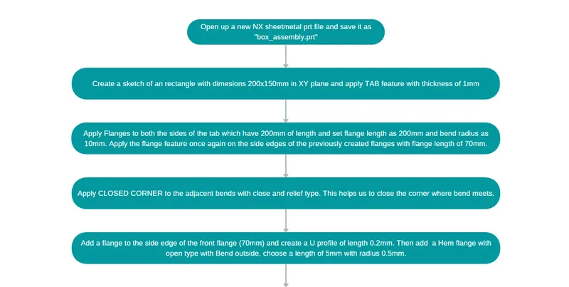
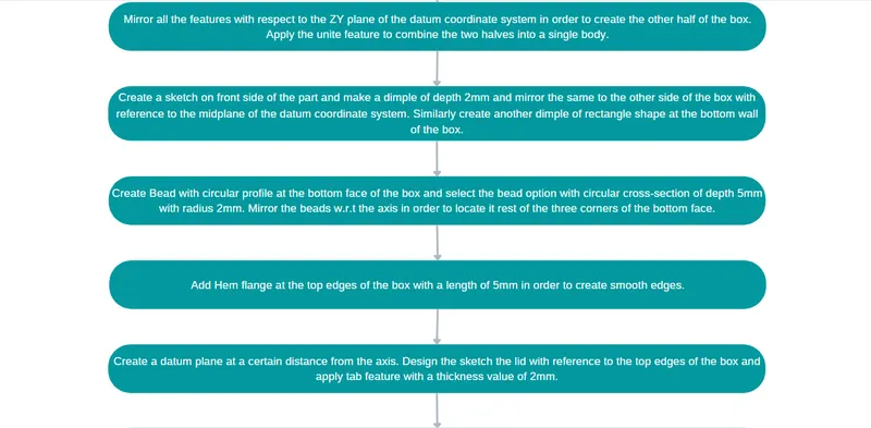
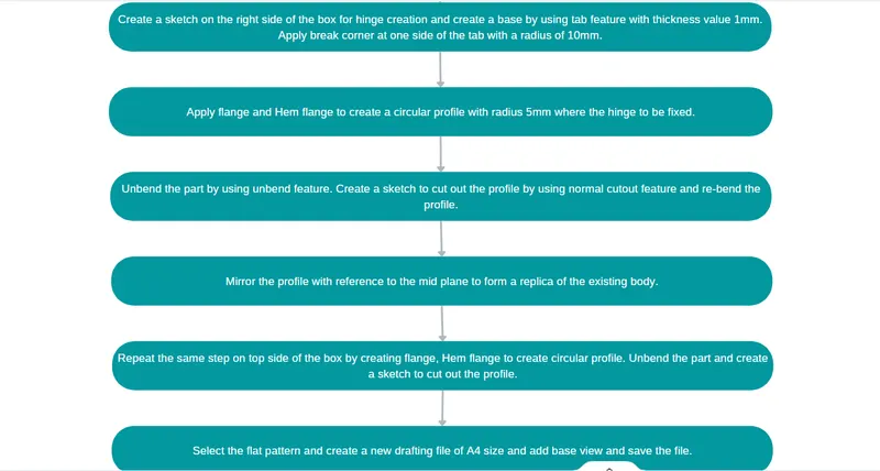
DESCRIPTION:
Following are the major feature used in creating the box assembly:
Datum plane: This feature is used to create a new plane with a definite distance and inclination w.r.t to the datum coordinate system.
Normal Cutout: This command is used to remove the unwanted material w.r.t a sketch.
Breake Corner: This command is used to create the sharp corners of any tab or flange rounded.
Sketch: It is basic command to draw geometries in a 2D plane having a fixed coordinate system.
Tab: This command is used to create a base feature by extruding a sketch along a vector by a definte thickness value or by adding material to existing faces and bend regions of sheetmetal part.
Closed Corner: This command is used to modify two flanges in one operation and to close the corner where the two flanges meet.
Flange: This command is used to add a flat flange at an angle to the face along the egde of which the flange is being added, it also adds a bend along the edge on which it is being created. A flange consists of bend region and a web.
Hem Flange: This command is used to create hemming portion along the edges it has many benefits like it prevents the exposure of sarp edges by folding them inside and hemming also increases edge stiffness.
Mirror Body: This command is used to mirror the parts w.r.t to a plane.
Unite: This command is used to combine the two parts into one part.
Dimple: This command is used to lift an area of the model by taking reference from a sketch profile that stimulates a stamping tool.
Bead: This command is used to lift the material along contour or profile created as a sketch that stimulates the stamping tool. Bead can also be created to stiffen the sheet metal part.
Mirror Feature: This command is used to mirror the required feature on the other side with reference to the axis.
Unbend: This command is used to flatten the 3D model by selecting a stationary face along which the required bended portions will be undended.
Rebend: This command is used to rebend rebend the flattened sheet material.
PICTURES OF THE BOX ASSEMBLY: