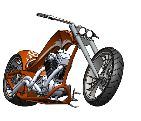
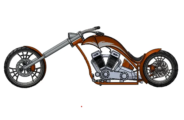
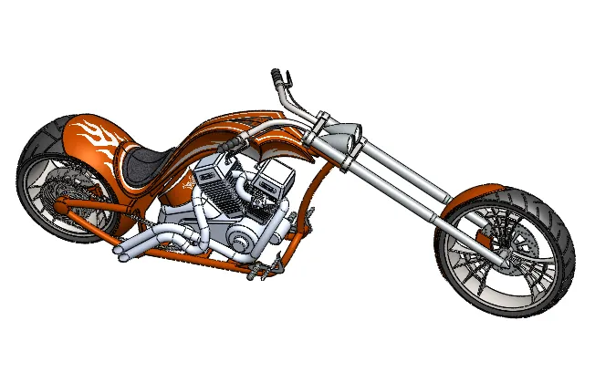
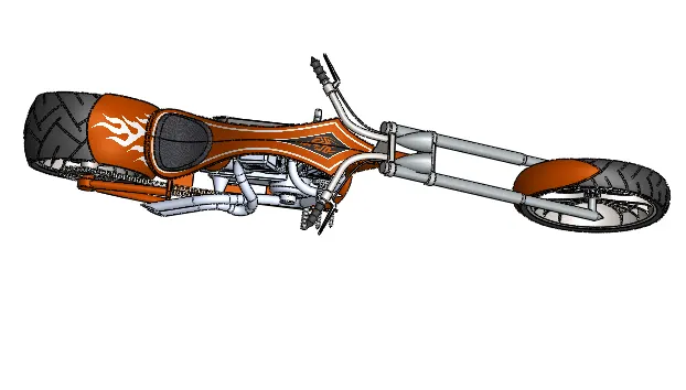
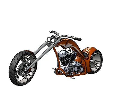
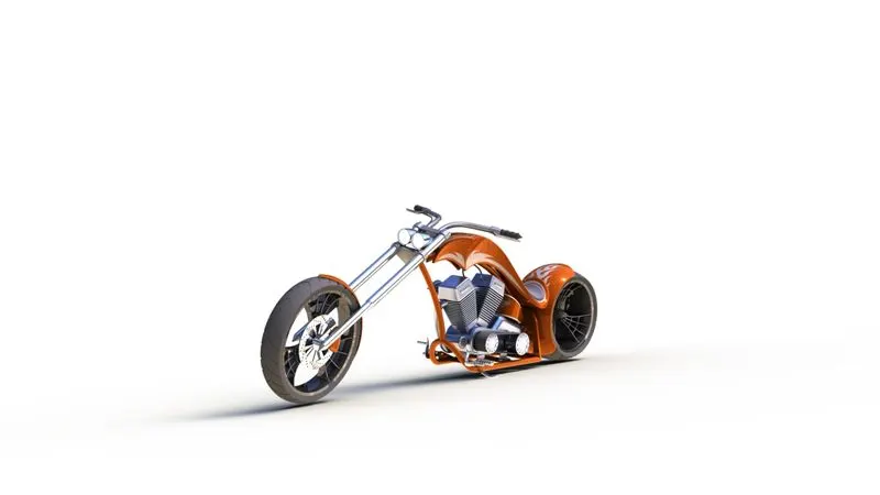
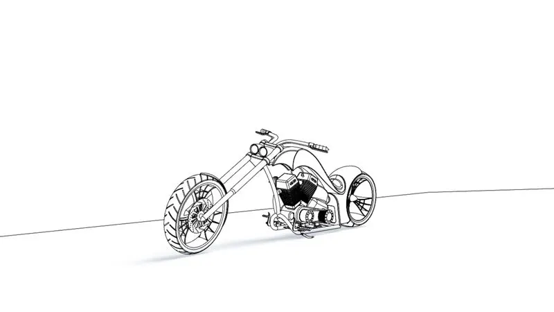
Photo Realistic Rendering
3D MODELLING OF THE AMERICAN CHOPPER USING SOLIDWORKS
OBJECTIVE
- To design and model all the exterior components of the American Chopper using various designing and modeling tools of SOLIDWORKS.
- To assemble all the modelled components in order to form complete American chopper model using mating tools in SOLIDWORKS.
- To render all the parts of American chopper using rendering tools of SOLIDWORKS.
INTRODUCTION
The methodology of creating a 3D model of the American chopper is elaborated in this report in a very detailed manner. SOLIDWORKS is used as a 3d modelling tool to create this 3D model.
In order to understand the processes involved in creating this model we first have to understand the underlying concept of computer aided 3d modeling.
So, computer aided 3d modeling is basically a three-dimensional modeling of physical structures and their properties, using specialized software on computer. In this case we are using Solidworks as a 3d CAD software.
In computer-aided-designing, in order to model any 3d object first we must create a 2d sketch, this sketch will describe the underlying geometry of that 3d object. The number of the sketches that must be created in order to model the object depends upon complexity of geometry of the object, and finally using those sketches as a reference different features or tools of the modeling software are being applied in order to create the 3d structure of the object.
DESIGNING METHODOLOGY/APPROACH:
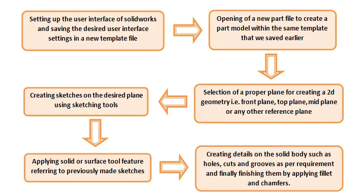
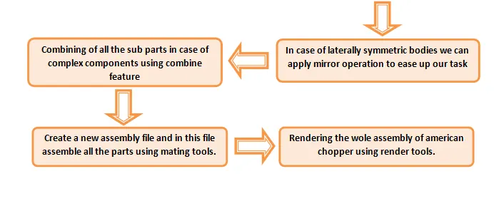
The general approach adopted to design the American chopper model is described with the help of flowchart as mentioned below.
TOOL DESCRIPTION:
In modelling different parts of the american chopper, various modelling tools are being used in order to carve out the desired geometry.These tools have been categorised as follows:
- Sketching tools
- Solid modelling tools
- Surface modelling tools
- Redering tools
SKETCHING TOOLS:
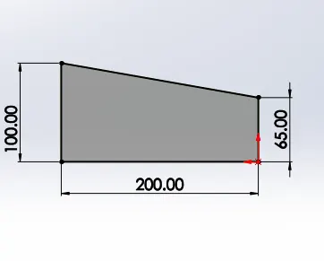
Line: One of the basic tool for sketching all kind of lines in a plane, it is basically used in creating solid bodies having some linear geometry such as front fork.
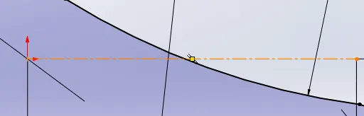
Constuction line: This tool is very useful when it comes to giving any reference to any sketch entity w.r.t origin, creating a reference plane, creating a revolve or extrude etc.
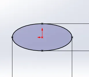
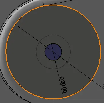
Circle/Ellipse: These are used for creating the bodies having cyclindrical, elliptical or dome shaped geometry such as clutch wires, circular chassis frames and elliptical cross-section of kick stand etc.
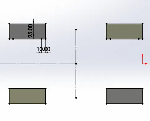
Square/Rectangle: Again these are used for creating bodies having linear geometry specifically those bodies which have square or rectangular cross-section. Example rectangular grooves on tyres, cyclinder block of engine.
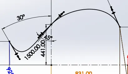
Spline: This is one of the most handy tools when it comes to creating a body having irregular curvatures, the best example is exhaust manifolds and alloy wheel rims.
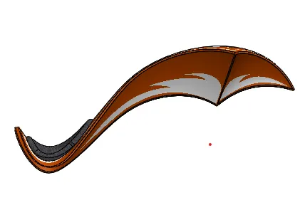
Arc: we can use this tool if we want to create partially circular entities in our sketches, it is used in creating bodies having rounded portions or certain curvature, for instance the transmission belt of the american chopper.
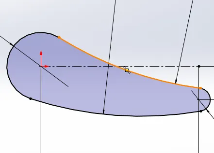
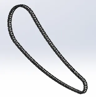
Offset: This tool is very useful when it comes to create cross-section geometry of hollow parts such as clutch wires, exhaust tubes etc. This tool prooved to be very handy in the creation of wheel rim geometry of the american chopper.
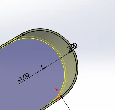
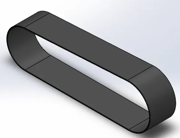
Convert entities: A very useful tool when you need the same sketch or sketch entity that you have already created in some other plane, so we can convert all those entities in a new plane which should be parallel to that of previous plane, otherwise we can see changes in parameters and orientation of sketch entities. Any changes in the base geometry will be automatically reflected in the plane in entities are converted.
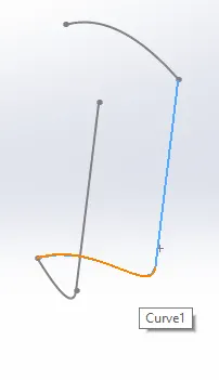
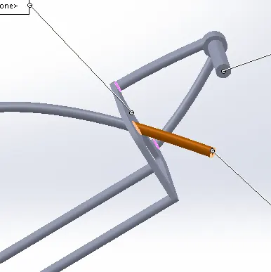
Project curve: This feature allows us to create a three dimensional curve which is basically an intersection of the projection of two separate curves made in two different planes. This feature is useful in creating the 3d curve profile for exaust system and gastank.

SOLID MODELLING TOOLS:
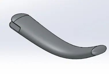
Lofted Boss/Base: It generates a solid body by lofting along a path(guide curve) with the help of two or more profiles which determines the cross-section of that lofted solid body. In designing the kickstand of the american chopper this tool is used.
Extrude Boss/Base: This is one of the most commonly used solid modeling tools which extrudes solid bodies out of previously made sketches(largely 2D) and the path of extrusion is generally linear. There are various methods available to us for applying this feature such as blind, through all etc. and we can apply them according to the need.

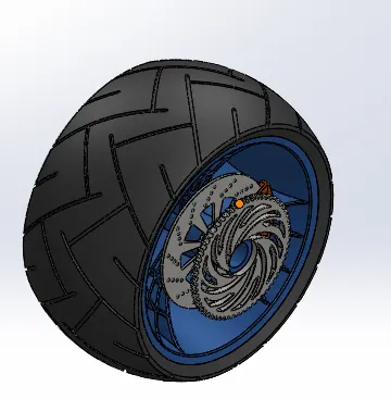
Revolve Boss/Base: This feature is generally applied to create circular objects and the path of extrusion is also circular. In modelling american chopper this feature is mainly used for designing the front wheel, rear wheel, front fender and rear fender.
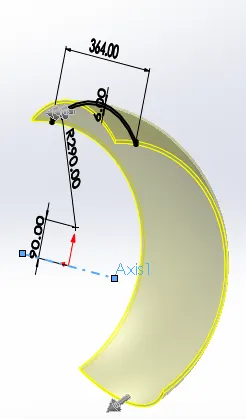
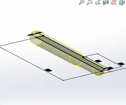
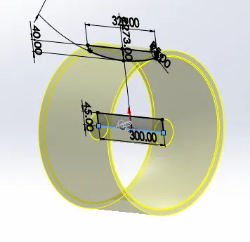
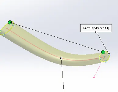
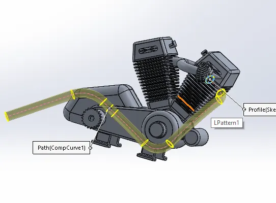
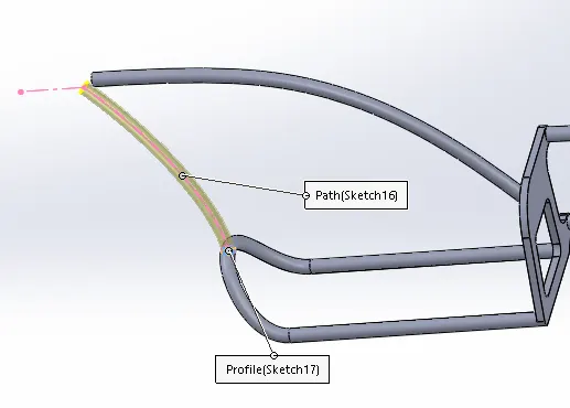
Swept Boss/Base:This is another extruding feature in solid modelling which allows us to create models with long wire like geometry. Two basic entities namely profile and path are needed in order to generate a solid body and it is done by sweeping the profile along the path.Exhausts, clutch wires, front fork handles are some of the bodies that are made using this tool.
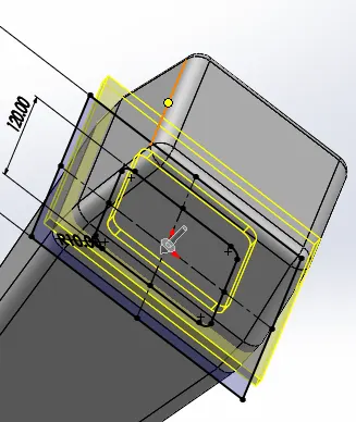
Extrude Cut: This feature allows us to cut sections completely or partially out of any solid body this tools prooved to be very instrumental when is comes to cut out grooves in tyres of front and rear wheel, creating slots in cyclinder block, creating grooves in air cleaner and in various other parts.
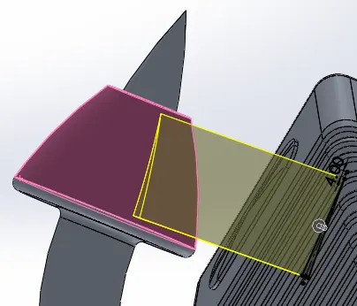
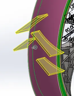
Revolve cut: The functioning of this tool is similar to that of extrude cut but it cuts the section in a circular path using a profile and this feature is used in creating the alloy rims for front and rear wheel and provided them with a good design.
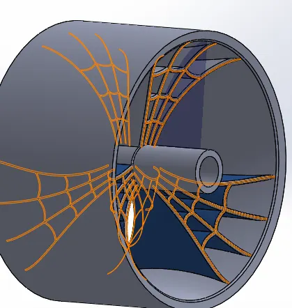
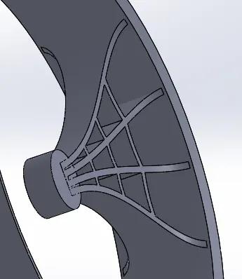
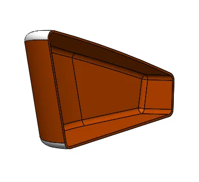
Shell:This feature converts any pre existing solid body into hollow shell and also allows us to leave out any face to create an open shell and to decide the thickness of this shell.This feature was used to create closed shell like fuel tank or gas tank and open shell in rear fender of the american chopper.
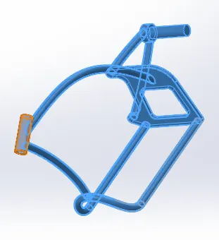
Combine: This feature combines two or more solid bodies to create a single body or another multibody part. This tool prooved to be very useful in modelling certain parts such as engine and sprocket chain which were composed of a large number of small sub parts, combining all those parts and creating a single body eased the task of applying appearance to that part and also assmbling that part with the rest ones.
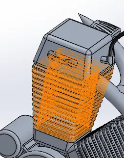
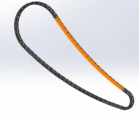
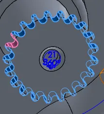
Pattern(linear pattern/ circular pattern/curve driven pattern): When it comes to modelling a body consisting of a large number of indentical components arranged in a specific pattern, this tool is very helpful, it patterns features, faces and bodies by taking a reference geometry. In modelling sprocket chain curve driven pattern was used, in order to create fins on cyclinder block linear pattern was used and in creating alloy rims circular pattern was used.
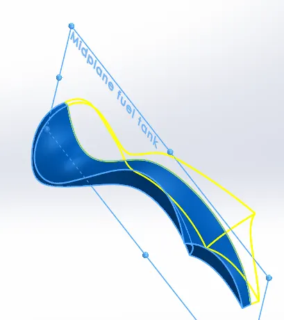
Mirror: This tool mirrors features, faces and bodies about a plane or a planer face it is generally used for bodies with any type of symmetry. It was used in mirroring half of the gas tank about its midplane with added features in gas tank model, mirroring the cyclindircal block with added features in engine model and mirrroring all the chain plates about the mid plane of sprocket chain model.
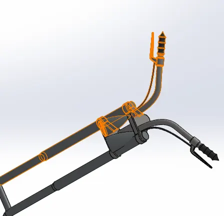
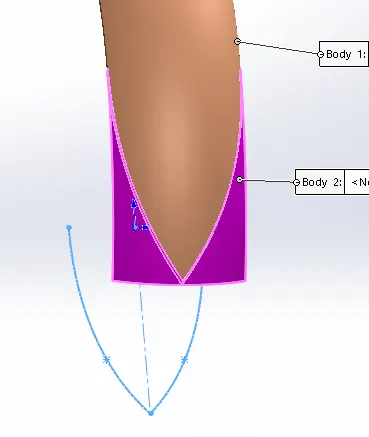
Split: This tool is basically used to split a body or surface into two or more segments with the help of refrence sketches, but here I used this tool mostly to trim off the non essential portion by consuming body. It was used in trimming off solid parts of front fender and rear fender model.
SURFACE MODELLING TOOLS
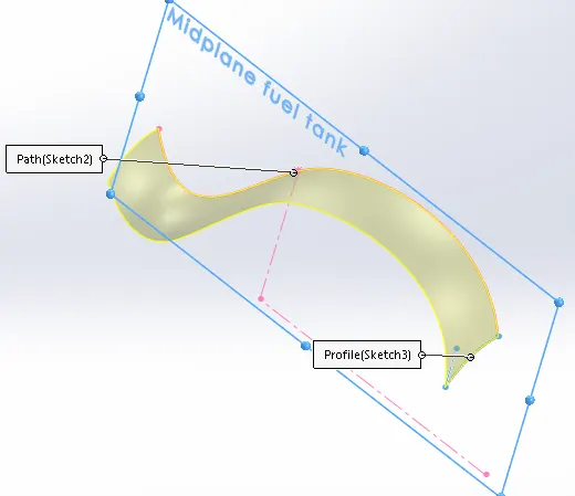
Surface Sweep: It is a surface tool which is used to generate surfaces of various kinds of shapes and curvatures, to use this tool we need a reference profile and a path through which the profile would be swept. I used this tool to generate the top surface of gas tank.
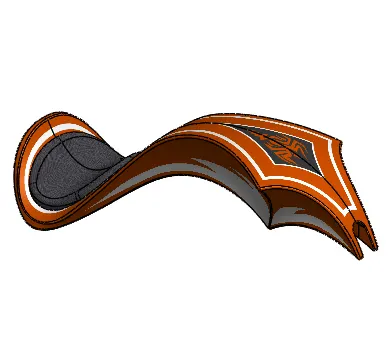
Surface extrude: surface extrude performs similar functions as sheet metal operations such as drawing and deep drawing. This feature is used to create seat on the gas tank of the american chopper by drawing out the top lofted surface of the gas tank in its back part and it requires a profile which is to be drawn on the surface.
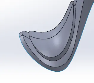
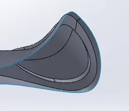
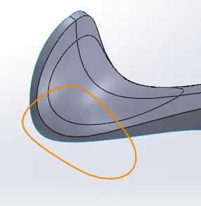
Surface Loft: The surface loft tool creates a shape by making transitions between multiple profiles and guide curves. This tool is very valuable for modeling complex surfaces such as the triangular shaped front part of gas tank.
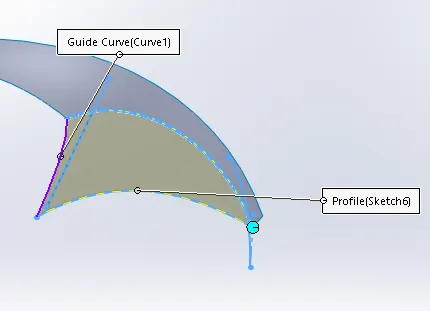
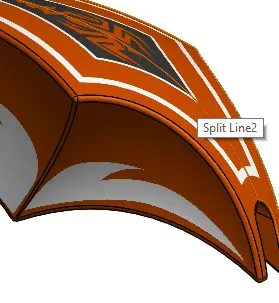
Boundry Surface: The boundary surface tool lets you create surfaces that can be tangent or curvature continuous in both directions (all sides of the surface). This tool was used in creating base walls of gas tank.
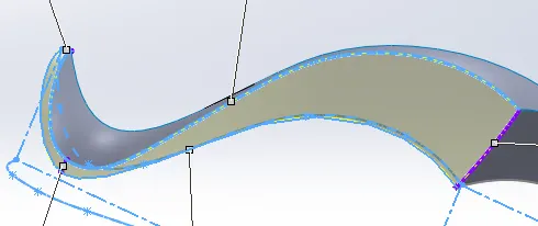
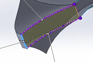
Surface knit: It is used to combine two or more faces and surfaces into one. The thing that should be kept in mind while using this tool is that the edges of the surfaces must be adjacent and not overlapping and surface do not need to be on same plane. This tool was used in kniting the surfaces of gas tank.
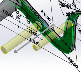
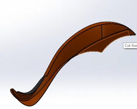
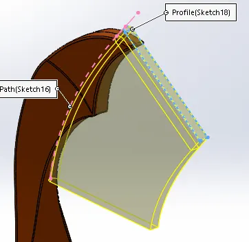
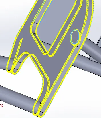
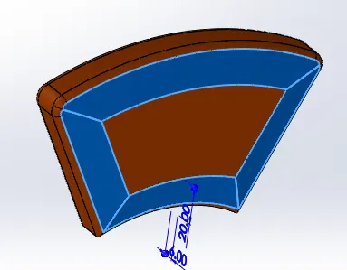
Cut Sweep: Cut sweep functionality is similar to cut extrude but the major difference between them is that for cut extrude to perform only profile is needed but in case of cut sweep both profile and guide curve are needed. This tool is used in performing intricate cuts such as in the case of gas tank as shown below.
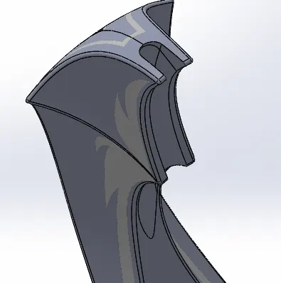
Fillet/Chamfer: fillet is basically applied to give rounded corners to a body and champher is applied to give sloped edges to a designed part or body. These tools were used in almost every part of the american chopper.
RENDERING TOOLS:
Appearance: This feature gives appearances to the modelled components as per their functionality and material specification. This feature helps in giving realistic look to the final assembly.
Scenes: It is a render tool which provides a visual backdrop behind a model. In Solidworks they provide reflections on the model. With PhotoView 360 added in, scenes provide a realistic light source, including illumination and reflections, requiring less manipulation of lighting.
Lights : This feature is used to illuminate the designed model as per our desired point or location in the model. It has several types such as directional lights, spot lights, point light and sunlight.
Camera: camera is very important feature to carry out final render because the final render are usually done over camera view. This view is taken out as per requirement of the designer how he wants to present the redered model.
PhotoView 360: It is a SOLIDWORKS add-in that produces photo-realistic renderings of SOLIDWORKS models. The rendered image incorporates the appearances, lighting, scene, and decals included with the model.
CONCLUSION:
Throughout the desighning process of the american chopper we observed that SOLIDWORKS is a very easy and useful tool to design any product because its features are easy to apply, it has a user friendly interface that allows easy handeling of tools and quick previews of the operations that are also very useful. In this modelling process we learned almost all kind of tools that would be required to design any product. Rendering in SOLIDWORKS gives the product a realistic look which is very useful when it comes to present the product.