Week 8 - Challenge 2 - Base Bracket Design
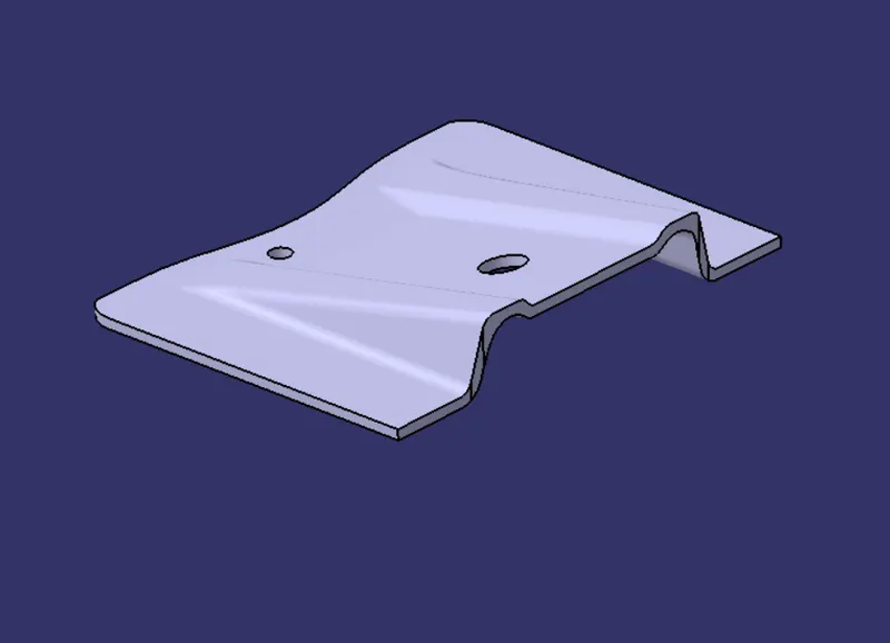
AIM: To create a Base Bracket model by using class A surface as an input reference in Catia V5.
INTRODUCTION:
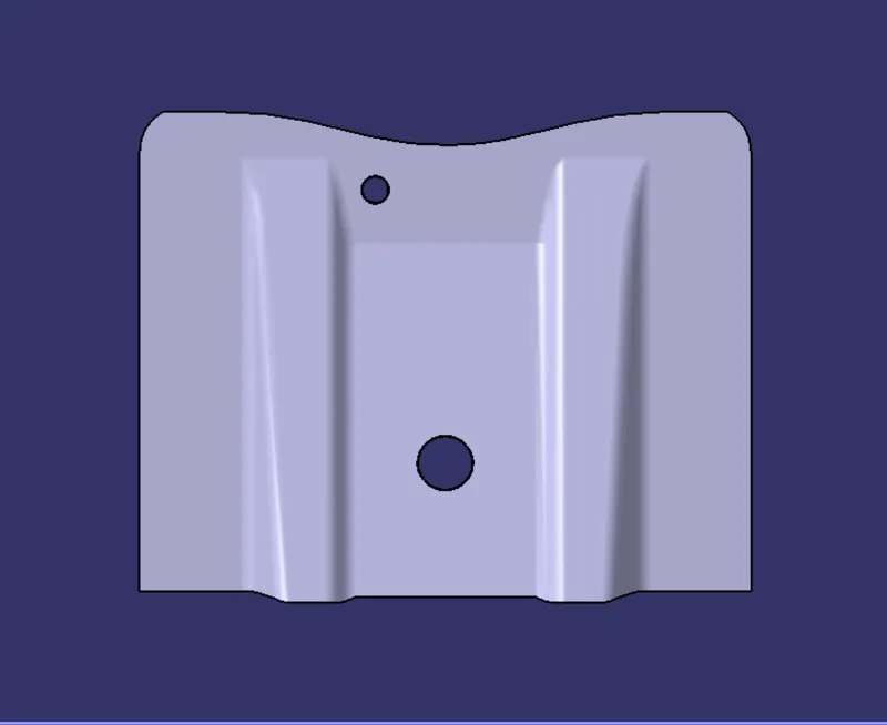
CLASS A SURFACE: Class A surfaces are the free form surfaces with zero thickness and shows only the outer aesthetics of a model. The class A surfaces are taken up as an input by the plastic design engineers to prepare funtionally viable model by adding up class B and C surfaces.
CLASS B SURFACE: The class B surface is the surface behind the class A surface which contains all the engineering aspects of the model.
CLASS C SURFACE: The class C surface is the surface with joins class A and B surfaces.
GENERAL APPRAOCH:
Following are the steps that we followed while modelling the base bracket
- Identification of Tooling Axis
- Executing Draft Analysis
- Creation of class B surface
- Creation of class C surface
- Creating a solid body from the closed surface
Following are the major commands that we used during the designing process.
- Boundary
- Un-Trim
- Join
- Trim
- Offset
- Extrapolate
- Point
- Line
- Feature Draft Analysis
- Edge Fillet
- Sweep
- Close Surface
CREATION OF TOOLING AXIS:
STEP1: Firstly we have to make sure that the class A surface is joined properly with no gaps in between the surface, to ensure this we will use the boundary command and join command.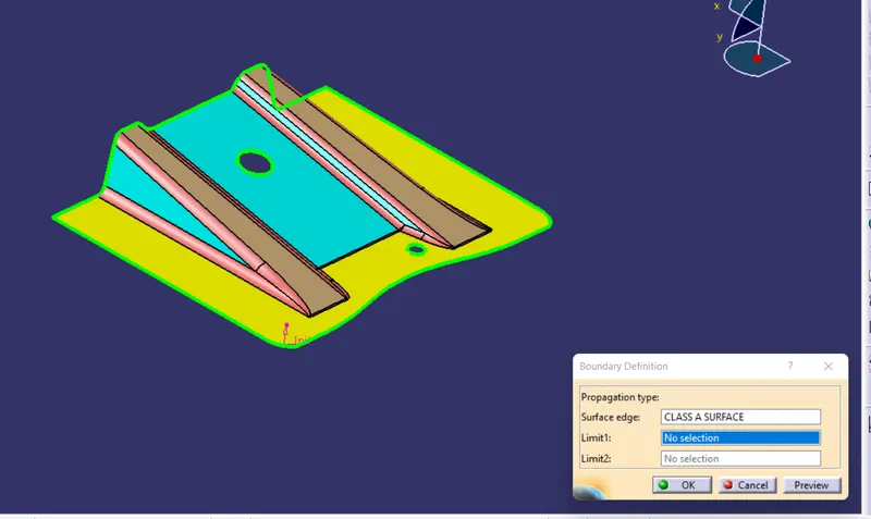
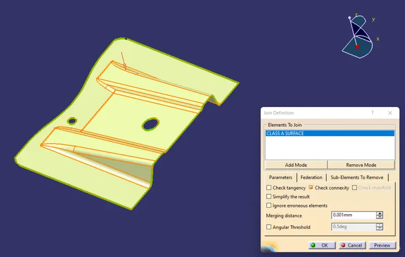
STEP 2: Analysing the model manually to see which direction is most suitable for the tooling axis.
STEP 3: On analysing the class A surface in isometric view we can clearly see two holes on it, so we have to find out which direction would be most suitable to clear these holes.
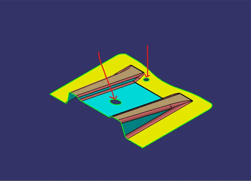
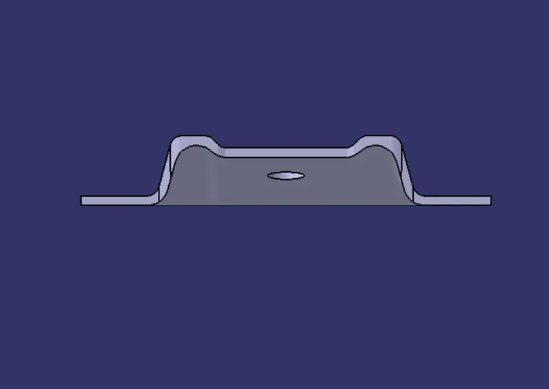
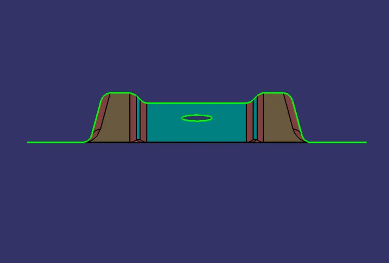
On looking from the front view we can see that one of the holes is not visibile so Y direction is not the suitable direction for tooling axis.
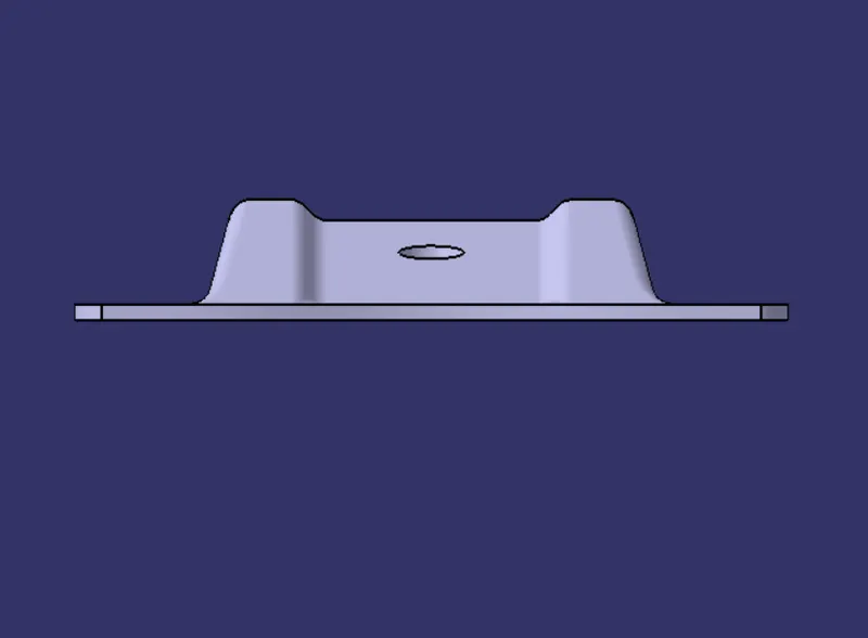
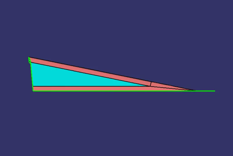
On viewing from the side view we can see that none of the holes is visibile so X direction is also not suitable for creation of tooling axis.
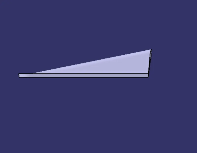
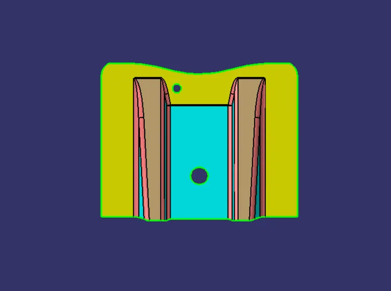
But when we see the model from top view we can clearly see both the holes which means Z direction would be the most suitable direction for tooling axis.
STEP 4: Since we find out the tooling axis direction, but we also have to clear the surfaces which are parallel to the the tooling axis direction(z direction).
For that firstly we will insert the axis system at the center of the big hole and then intersect the class A surface with the ZX plane of the axis system. As we can see there is no any surface that would create a problem during tooling so we will leave it as it is.
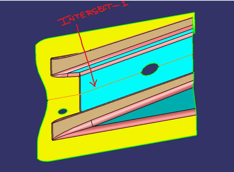
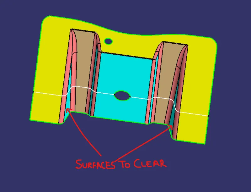
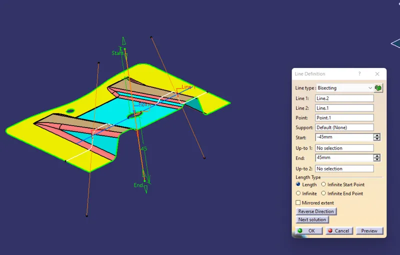
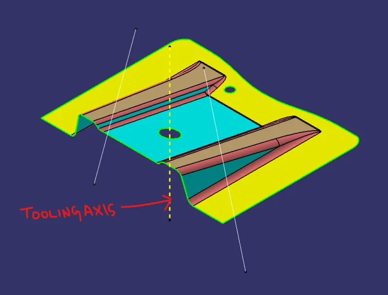
Similarly we will intersect the ZY plane of the axis system with the class A surface, here we can see that two surfaces shown in the figure can create a problem during tooling process. For that we will create lines along these two surfaces and create a bisecting line in between them and hence this line will be called as the main tooling axis of the model.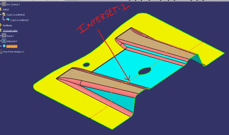
DRAFT ANALYSIS:
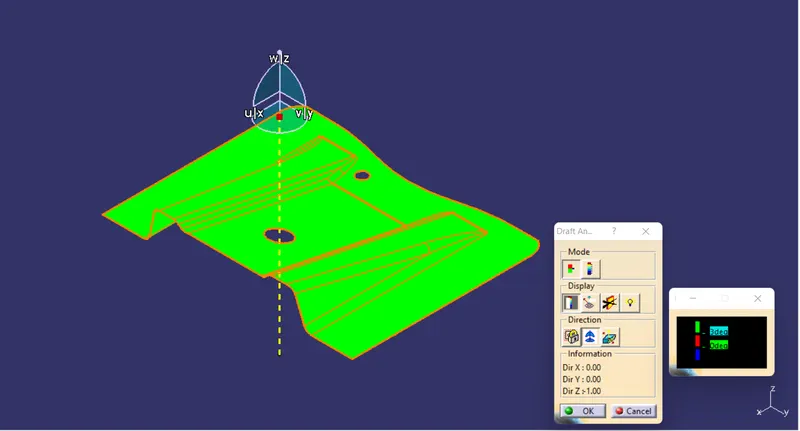
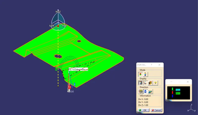
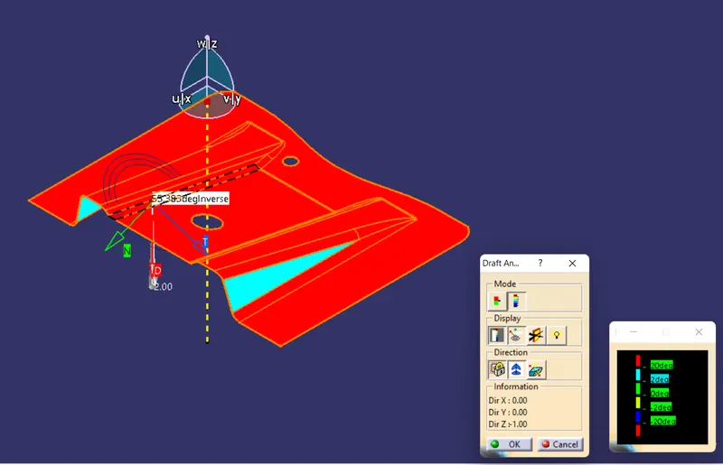
STEP1: Go to Insert>Analysis>Feature Draft Analysis
STEP2: Click on the compass icon and align the compass with tooling axis.
STEP3: First click on the quick analysis mode and then click on the surface, make sure that the surface is within the permissible limit of the draft values(3 degrees).
STEP4: Make sure that the surface should appear green in colour, if it is showing blue colour then click on inverse draft direction.
CREATION OF CLASS B SURFACE:
The general approach for creating a class B surface from class A surface is explained with the help of following steps.
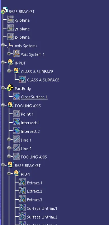
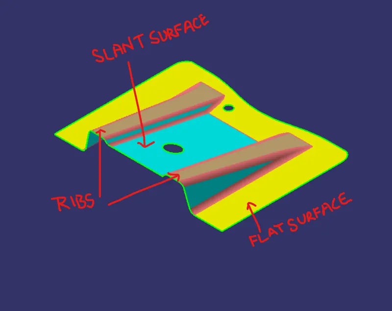
- Firstly we will divide the class A surface into different sub surfaces according to their orientation and geometry. So as we can see in the below picture that our class A surface can be divided into three main sub surfaces i.e ribs, slant surface and flat surface.
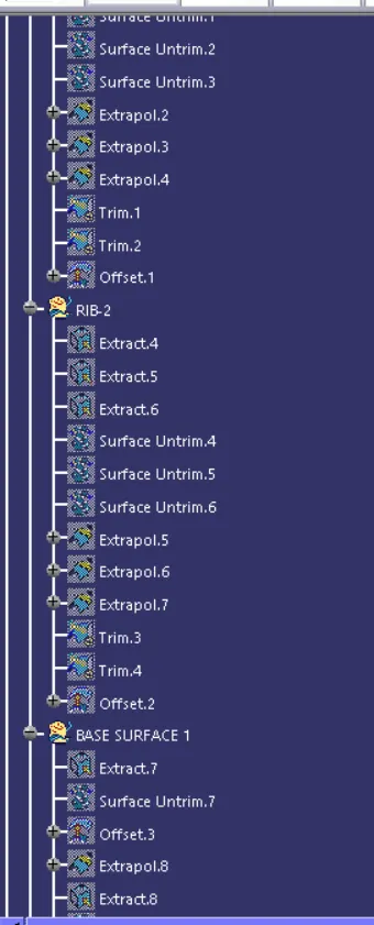
- After indentifying all the sub surfaces we will extract these surfaces one by one using EXTRACT command with no propogation option.
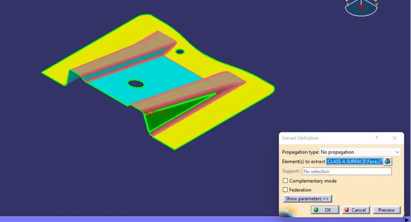
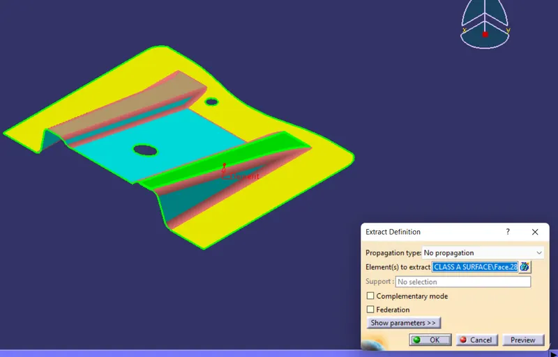
- Then all these surfaces are un-trimmed using UN-TRIM command to bring them back into their primary shape.
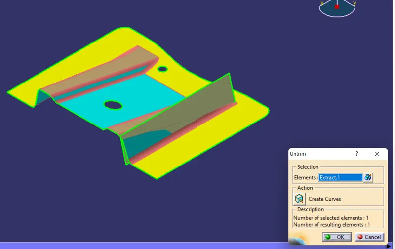
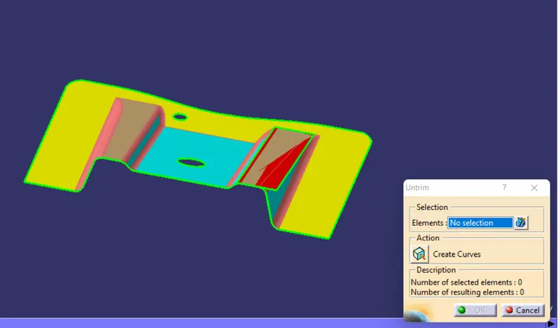
- Next thing will be to extrapolate the un-trimmed surface using EXTRAPOLATE command to ensure that all of them intersect each other.
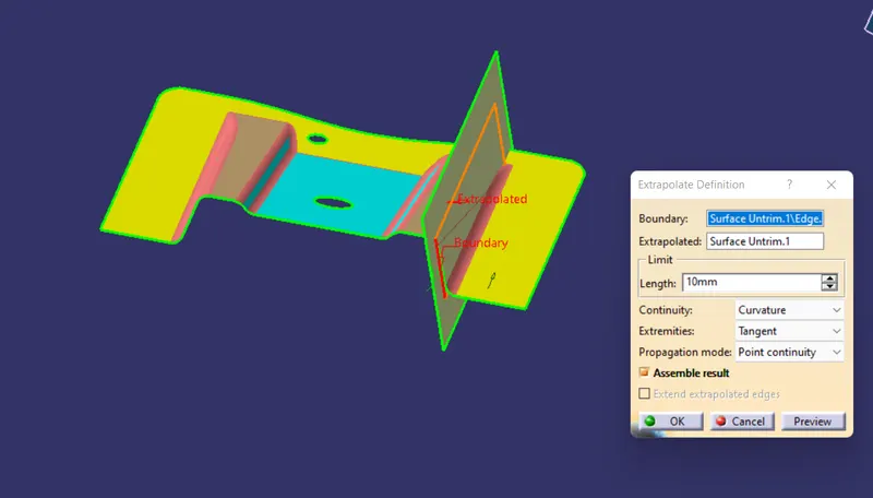
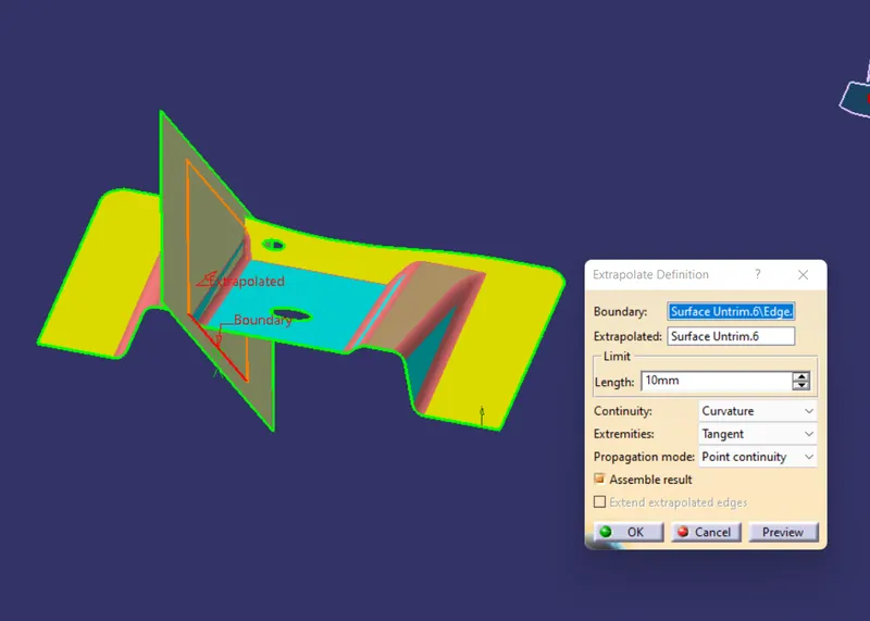
- In order to create a thickened surface we will give offset to each and every surface using OFFSET SURFACE command, here the offset distance will be equivalent to the thickness of the model which is 2.5mm.
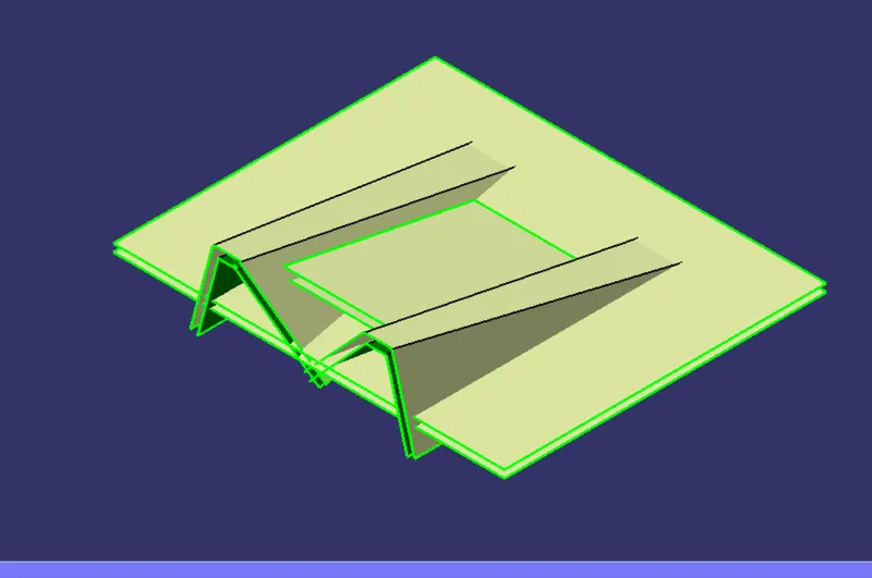
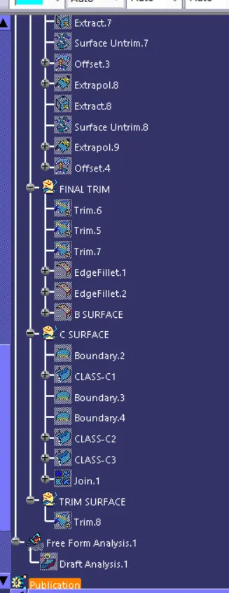
- Use the TRIM command to trim off the extra parts off the individual surfaces and make them a single entity at the same time. Using this command we will create both the ribs and we will use the same command untill we create a final trim which is nothing but class B surface as a single entity.
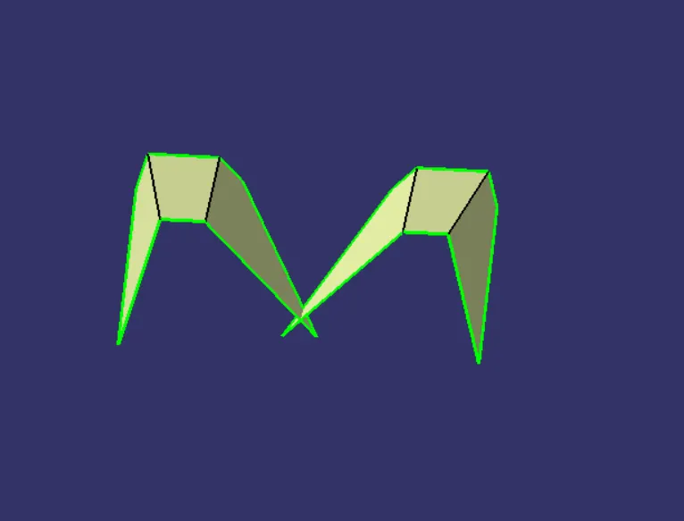
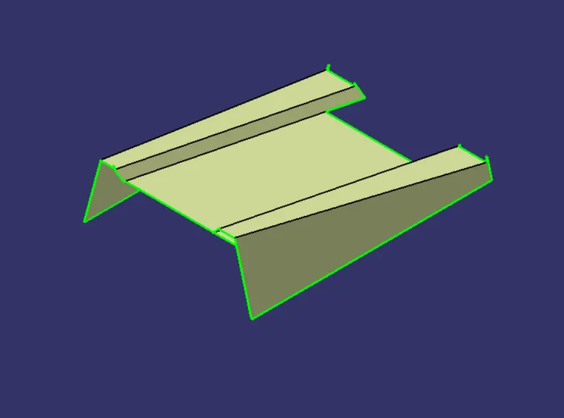
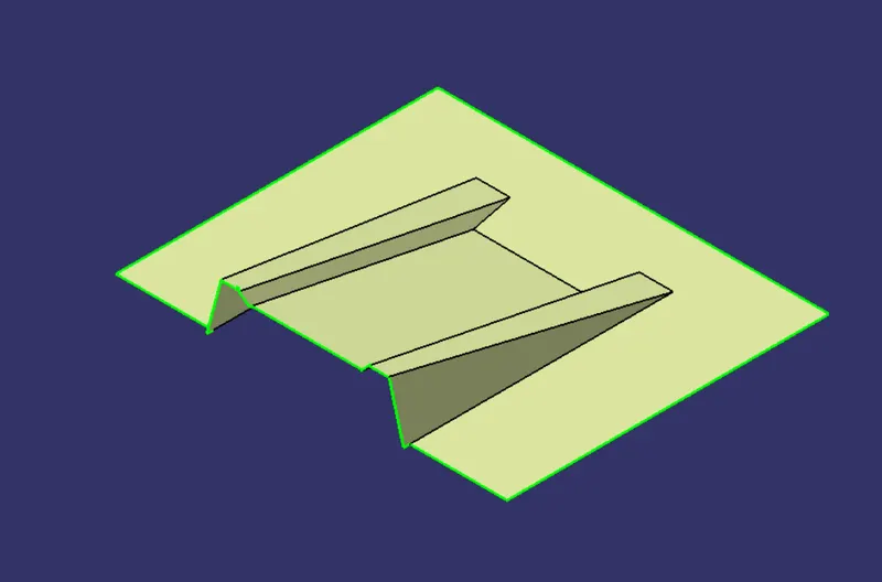
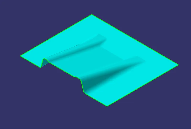
- Finally we will give fillets to the edges of the class B surface and the value of the fillet radius will be equal to the corner radius of class A surface edges plus the thickness of the model (3mm+2.5mm).
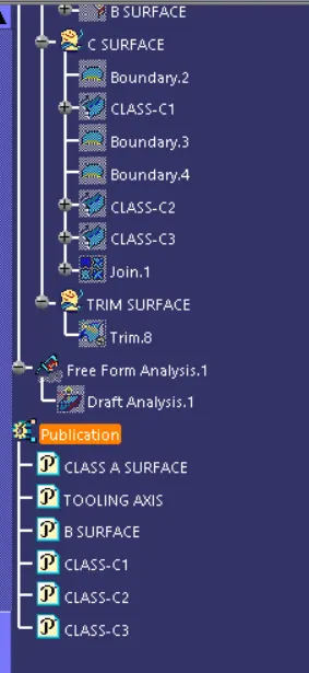
CREATION OF CLASS C SURFACE:
Following are the steps followed to create a class C surface
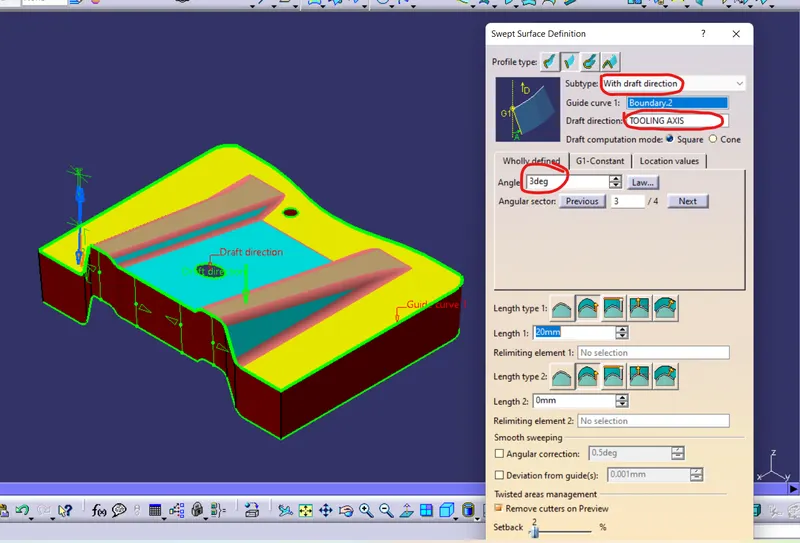
- Extract the boundary of the class A surface using the BOUNDARY command.
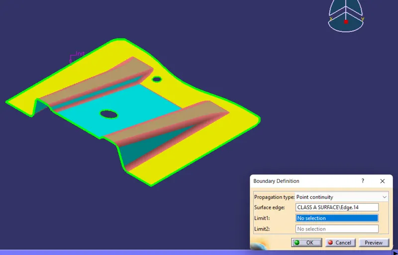
- To create class C surface use SWEEP command and select "with draft direction" subtype and select the boundary of the class A surface as the "guide curve" and click on the tooling axis as the "Draft direction".
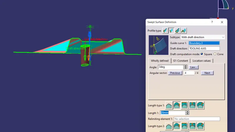
- Repeat the process to create class C surfaces for the holes.
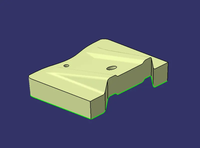
- Join all the B surfaces with class A surface
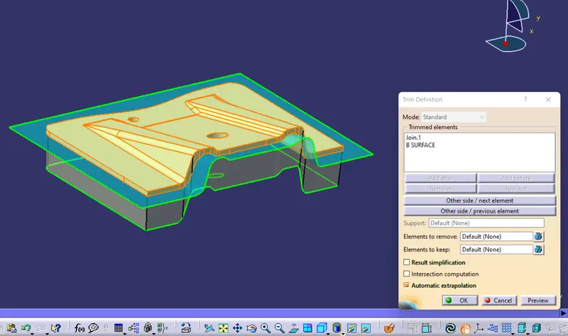
FORMATION OF THE CLOSED SURFACE:
Now we have with us all the surfaces i.e A, B and C so we will apply the final trim here to join all these surfaces to form the closed surface of the base bracket model.
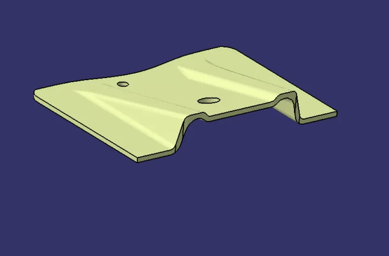
CREATION OF THE SOLID BODY FROM THE CLOSED SURFACE
In this final step we will use the CLOSED SURFACE command to create a solid part from the closed surface in part design workbench.