FINAL INDEPENDENT PROJECT
3D MODELLING AND RENDERING OF BOFORS 40MM AA GUN USING SOLIDWORKS
ABSTRACT
The purpose of this independent project is to demonstrate the tool knowledge which is being acquired by me throughout the “Ultimate Solidworks Course”.
The methodology and modeling approach used in designing the individual components of the Bofors 40mm AA gun is being explained in this report in a structured manner. The functioning of the individual parts of the model has also been described in this report in a brief manner.
During the modeling process of the above system I didn't get into the detailed functioning of its inner mechanisms, I just worked upon the outer appearance of the system and inducted its basic movements in the model.
OBJECTIVE
- Choosing a mechanical system (Bofors 40mm Anti-aircraft gun) in order to prepare a 3d model of the same in Solidworks.
- Collecting detailed information of the system selected for designing i.e. data related to functionality, operations, geometric parameters etc.
- Designing and assembling the subsystems with Top-Down approach.
- Introducing Dynamics into the system using Solidworks motion tools.
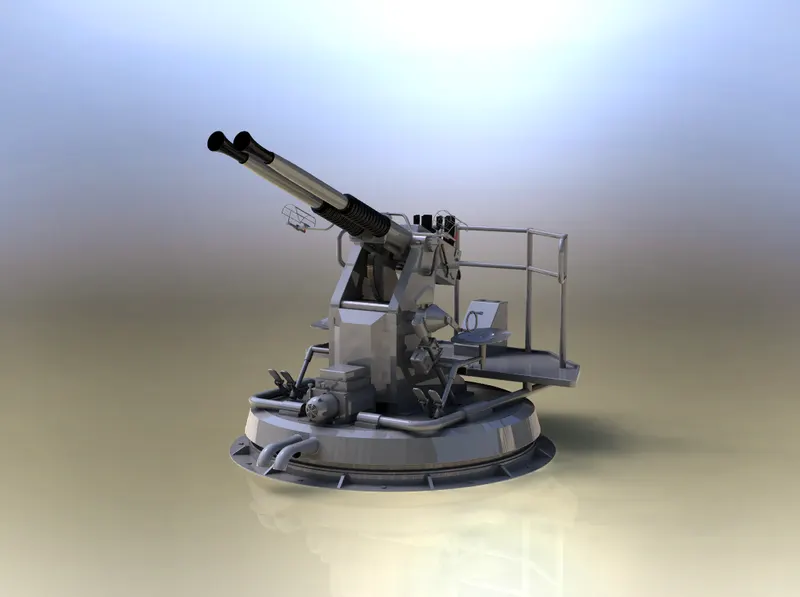
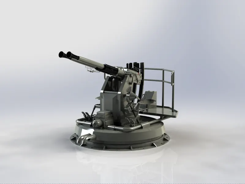
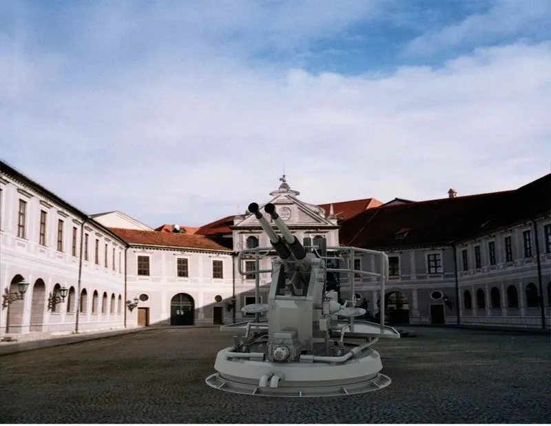
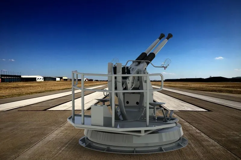
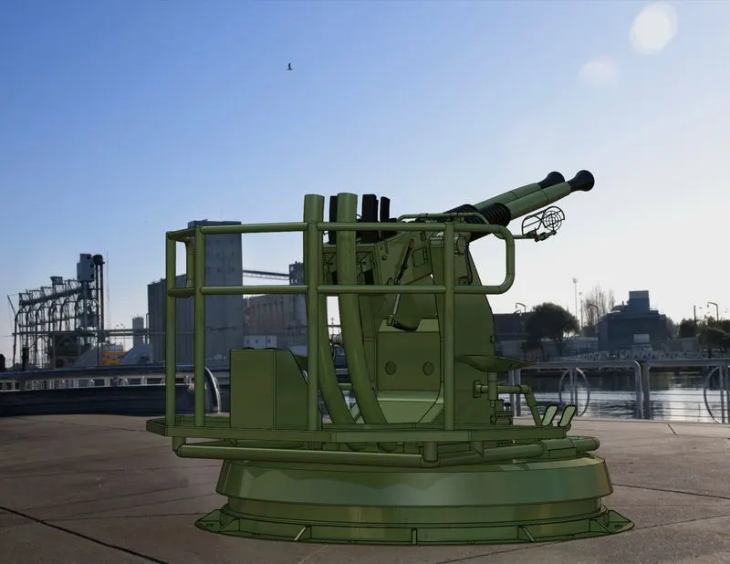
- Rendering the model with appropriate background details using the render tools.
INTRODUCTION
- Bofors 40mm AA gun is being picked up as a physical system on which designing is being performed.
- The Bofors 40mm AA Gun, often referred to simply as the Bofors gun, is an anti-aircraft/multi-purpose auto cannon designed in the 1930s by the Swedish arms manufacturer AB Bofors.
- It was one of the most popular medium-weight anti-aircraft systems during World War II, used by most of the western Allies as well as by the Axis powers.
- This weapon was used on almost every major USA and UK warship of World War II and was a very potent AA gun.
- Newer, faster-firing versions of this weapon are still in production by Breda as well as Bofors.
BLUEPRINT DETAILS
The blurprint details are taken from URL :https://drawingdatabase.com/bofors-40-mm-gun/
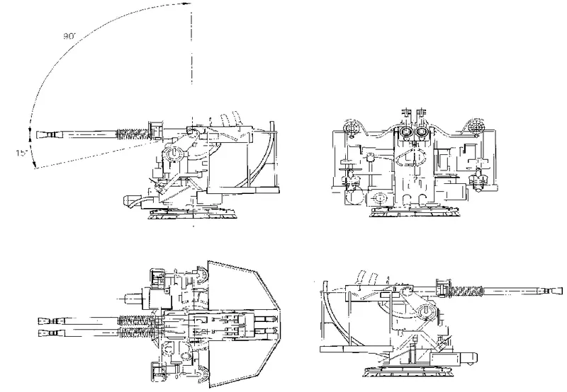
MAJORS PARTS
- Mounting pedestal
- Loader platform
- Carriage
- Slide assembly
- Firing pedal
- Trainer’s seat
- Pointer’s seat
- Trunnion
- Elevating arc casting
- Elevator mechanism
- Barrel and recoil spring
- Sight
- Train power drive
- Case discharge chutes
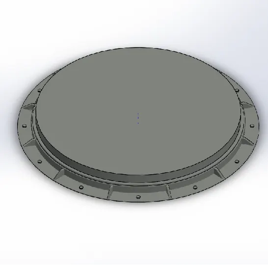
Mounting Pedestal
- This is a kind of platform on which all the other parts of the anti-aircraft gun are mounted.
- This platform is generally fixed on the ground surface or on the deck of battleship with the help of nuts and bolts.
- All the mounted parts rotates together on this mounting pedestal with the help of a gear train driven with the help of electric motor(train power drive).
- Majorly used modelling tools in the designing process of this part included boss extrude, offset entity, circular pattern, fillet and chamfer.
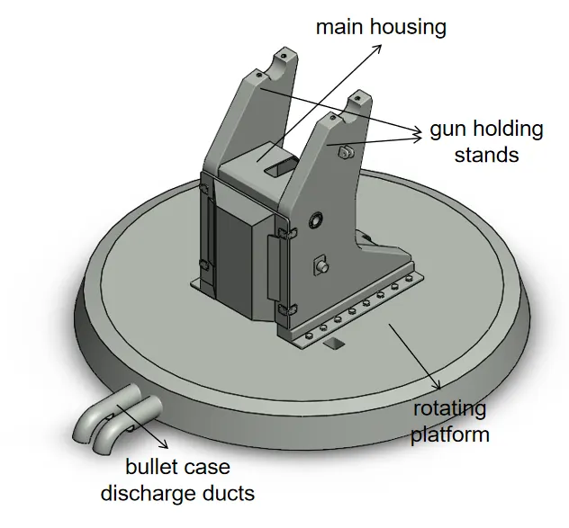
Carriage
- Carriage is the main body frame of the Bofors anti-aircraft gun. All the parts are in direct contact with the carriage.
- It houses the elevator mechanism which is responsible for changing the inclination of the slide assembly along with the barrel.
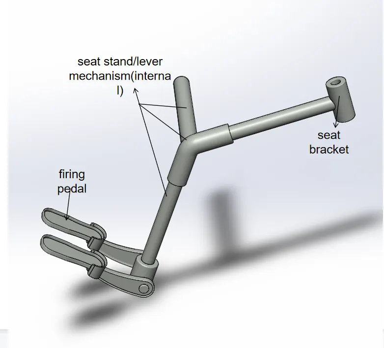
- It also contains the lever mechanism which connects firing pedal with trunion or firing tappet.
- Following are the tools used in the designing of carriage:- boss extrude,sweep, revolve, Cut extrude, linear pattern, mirror, combine, refrence plane thread.
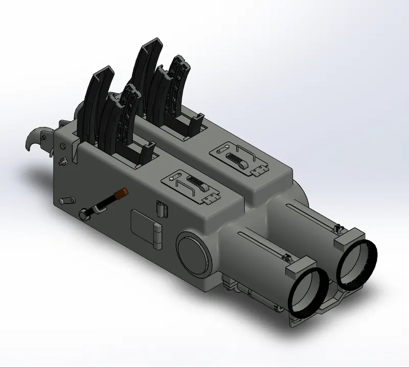
Slide And Loader Assembly
- It is a steel casing which positions and provides working surface for other parts of the mechanisms.
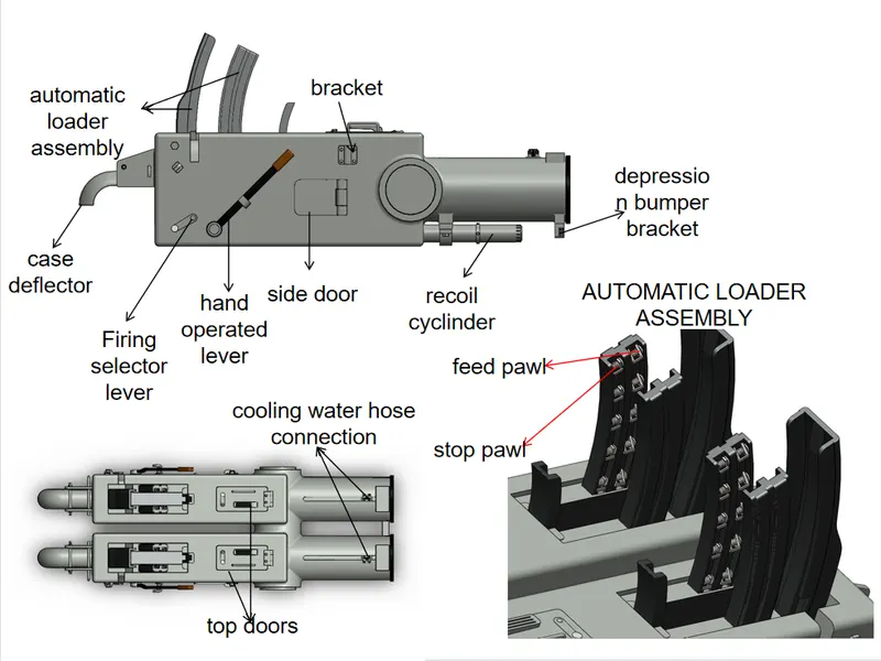
- It consists of Slide Assembly, Breech Mechanism Assembly, Loader Assembly, Recoil Cylinder Assembly, and Barrel Assembly (excluding barrel).
- Major tools used are extrude boss, extrude cut, swept boss, swept cut, curve driven pattern, thread, circular pattern, project curve, reference plane, split.
Trunnion
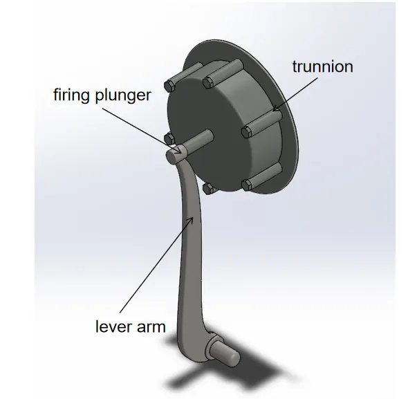
- The trunnion, contains the firing plunger and crank of the trigger mechanism.
- The trigger mechanism get activated when the firing plunger is pushed inside the trunnion by the help of lever arm.
- The lever arm is connected to the firing pedal via levers. When the operator pushes the firing pedal the lever mechanism attached to it enables the firing plunger to trigger the fire.
- Major modelling tools used are spline, split, circular pattern, boss extrude, revolve, split, spline etc.
Firing pedal
- Firing pedal comes under the firing mechanism of the Bofors AA gun.
- When the gun operator pushes the plunger to downwards, it activates the lever mechanism associated with it and enables the trigger mechanism to fire the projectile.
- Major modelling tools are revolve boss, cut extrude, shell, fillet, boss extrude.
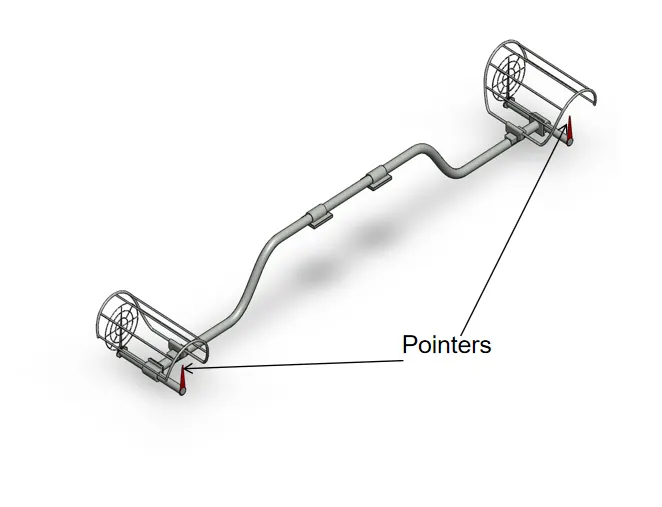
Trainer’s and Pointer’s Seat
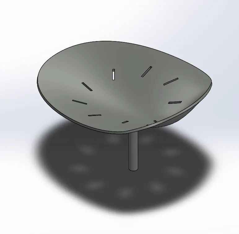
- The seat used in bofors AA gun is made out of a steel sheet which is being drawn in a curved shape to create a sitting space.
- Along with that piercing is being done on the sheet.
- Major designing tools used are spline, project curve, surface fill, thin extrude cut, circular pattern.
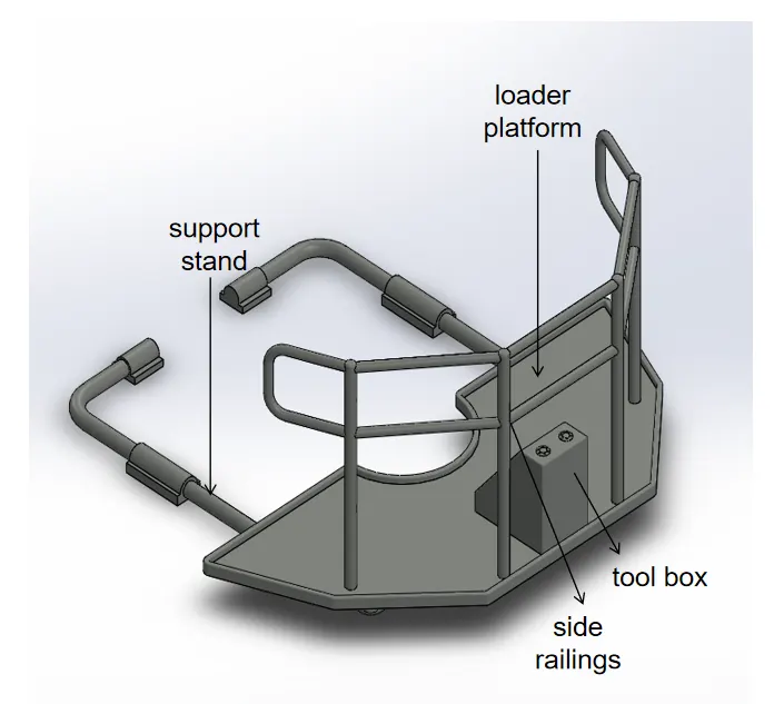
Loader Platform
- It is a platform attached to the carriage or main body of the gun.
- The purpose of this platform is using it for loading ammunition or maintenance work of the slide or loader assembly.
- Modelling tools used for designing are extrude boss, revolve boss, sweep boss, mirror, shell, chamfer and fillet.
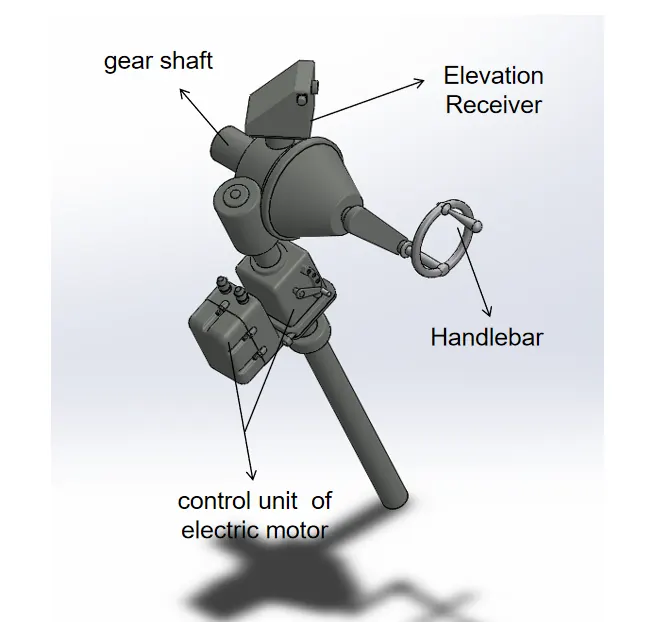
Elevator Mechanism
- The work of elevator mechanism is to control the inclination or elevation of the gun barrel which enables the projectile to be fired at different elevation points.
- In addition to that it also controls the rotational movement of the Bofors AA gun.
- Features used in the modelling of elevator mechanism are revolve, swept cut, extrude boss, mirror, linear pattern, reference plane.
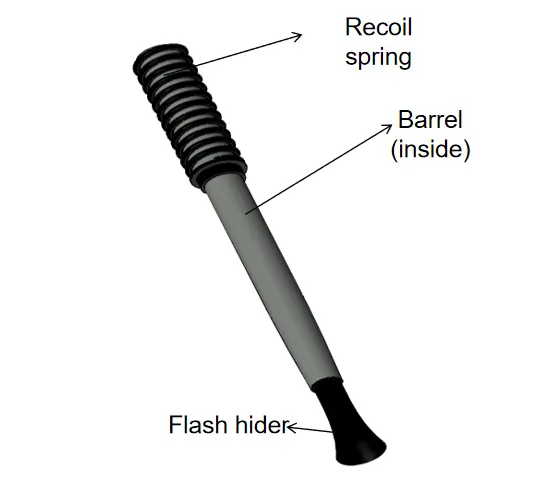
Barrel and Recoil Spring
- The projectile after being fired passes through the bore of the barrel, here in this model the dia of the bore is 40mm and the lenth of the barrel is 2500mm.
- The barrel consists of a water jacket which lowers the temperature of the barrel during firing.
- In addition to that there is a recoil spring attached to back end of barrel which dampens the reaction force of the fire.
- spline, Helix curve, revolve and sweep boss are the major tools used in the modelling process of barrel.
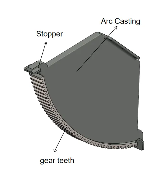
Elevating Arc Casting
- Elevating arc casting is the part of elevator mechanism.
- This arc is attached to the block containing slide and loader assembly and rotates with the help of elevator mechanism up to a specific range of angle.
- Circular pattern, cut extrude, split, block are some of the features used in the modelling of elevating arc casting.
Sight
- Sight is used to take aim on the target by the help of its wedge shaped pointer.
- It is mounted on the top of barrel assembly(without barrel).
- Major features used for the modelling of sight are extrude boss base, project curve, thin extrude, sweep, spline, split, cut extrude, revolve.
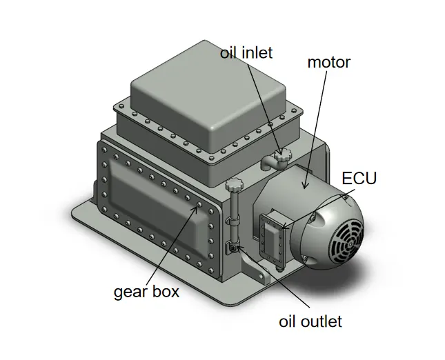
Train Power Drive
- Train power drive consists of an electric motor coupled with a gear box.
- It provides the necessary power to run the gear train centered on the top of mounting pedestal which is responsible for rotation of carriage on the mounting pedestal.
- The power of the electric motor of train drive ranges between 5HP to 10HP.
- modelling tools used are Extrude, cut extrude, revolve, swept cut, linear pattern, create and insert block, split, fillet, chamfer.
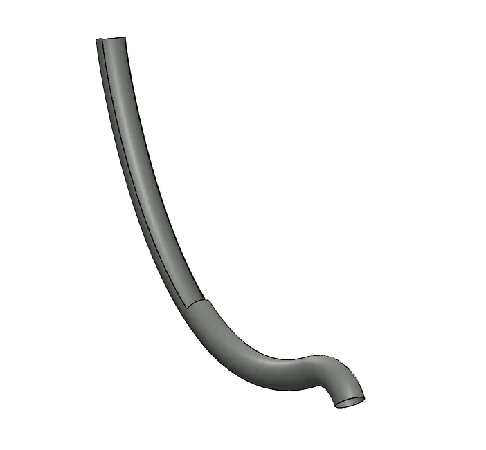
Case Discharge Chutes
- This is a sloping channel or slide for conveying bullet cases or shells to a lower level away from the gun.
- This is done to prevent any accident during firing operation as these cases are heavy and very hot at the same time.
- surface sweep, thicken, spline, swept cut are some of the modelling tools are being used here.
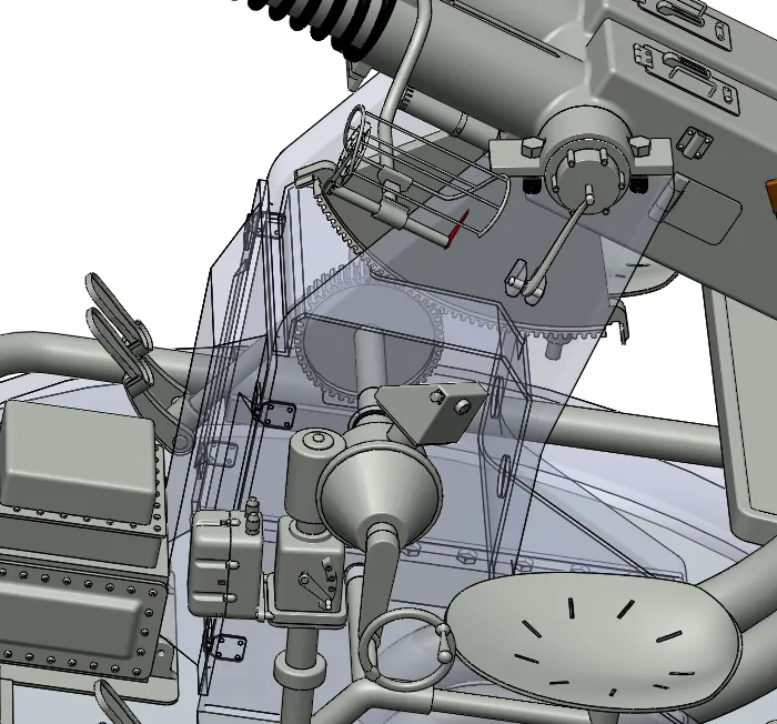
ELEVATOR MECHANISM
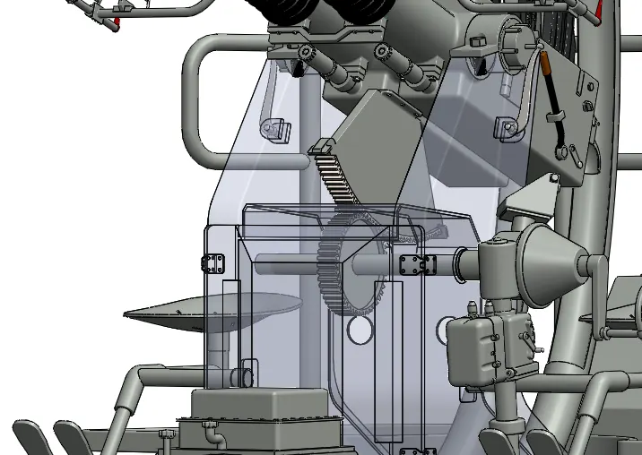
the elevator mechanism is responsible for the elevatory motion of the gun muzzle, it consists of a arc casting and a pinion gear both meshed with each other, on one hand the arc casting is attached to the gun casing and on the other hand the pinion gear is connected to the handle bar with the help of gear shaft. On rotating the handle bar the pinion gear is rotated and this motion is finally transfered to the elevating arc which helps to position the barrel at desired elevation angle.
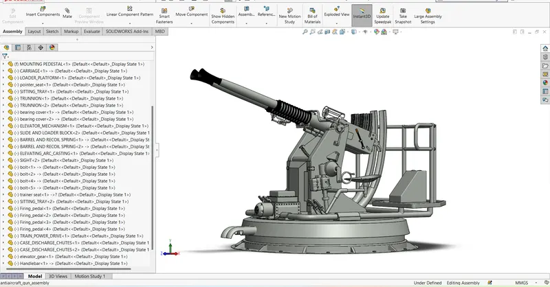
ASSEMBLY
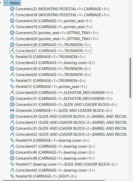
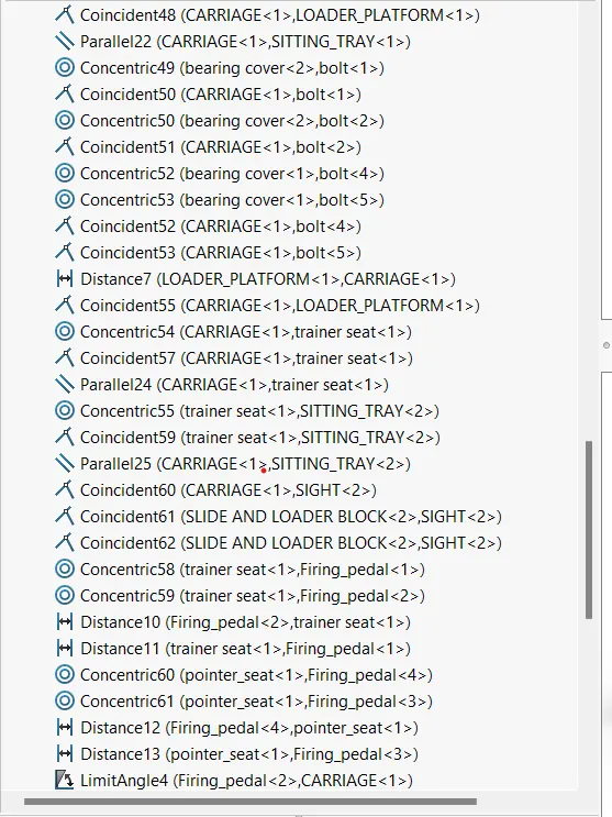
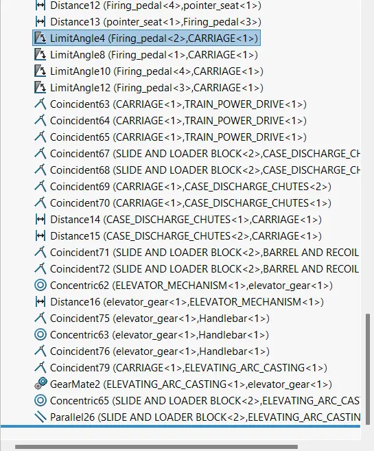
MATES APPLIED
CAMERA VIEWS
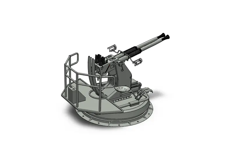
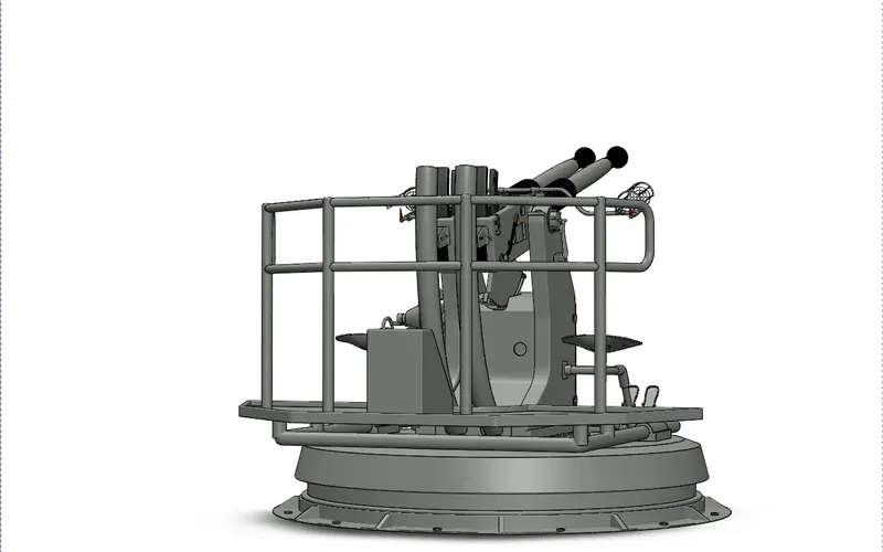
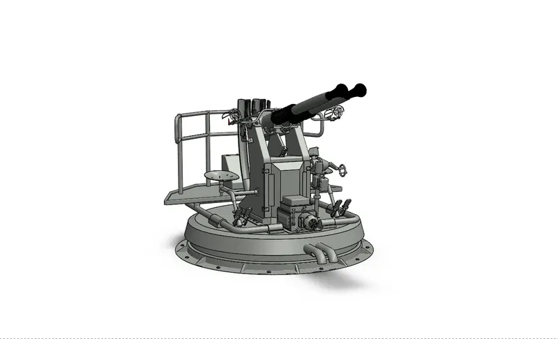
RENDERED VIEW
Conclusion
Throughout this independent project I learned how to build a dynamic 3D model of a complex system like Bofors AA gun from scratch. I tried to make the model as dynamic as possible within the limited time that I had been alloted to complete this challenge. In this independent project I applied all the tool knowledge with right approach that I learned form the previous challenges assigned to me by skill lync. Due to lack of availability of all four sided views of the above system I did some of the changes in this model by myself so that it looks functionally viable.
The model can be made much more dynamically functional by incorporating some more mechanisms into it like breech block mechanism, slide mechanism, trigger mechanism etc. Rendering can be much more improved with the help of solidworks visualize which was not incorporated in this model because of some technical issue with the software.
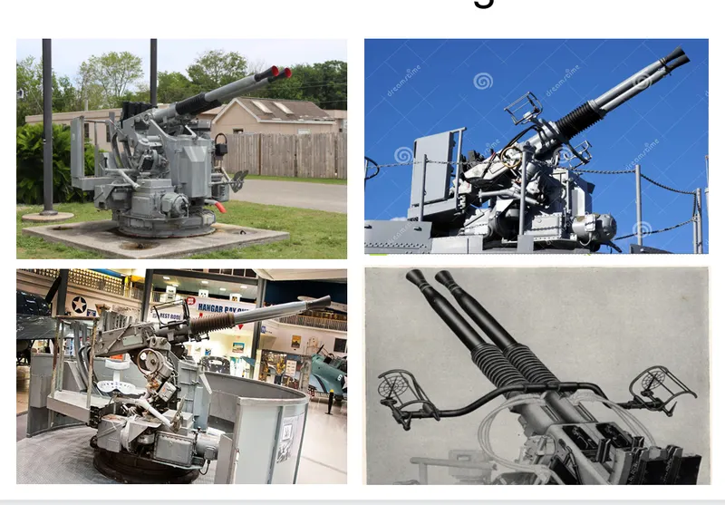
REFERENCE IMAGES
REFERENCE LINKS
- https://maritime.org/doc/bofors40mm/index.htm
- https://military history.fandom.com/wiki/Bofors_40_mm_gun
- http://www.navweaps.com/Weapons/WNUS_4cm-56_mk12.php
- https://free3d.com/3d-model/bofors-40mm-anti-aircraft-gun-8515.html
- https://drawingdatabase.com/bofors-40-mm-gun/
- https://youtu.be/Supmhc4sizw
- Ashish Kumarimpressive man you did crazy research