Week 9 - Attachment Feature Creation - Challenge 1
CREATION OF ATTACHMENT FOR CENTRE CONSOLE COIN HOLDER
OBJECTIVE:
- To create ribs for centre console coin holder according to the design rules followed by the OEMs
- To create tooling axis for the centre console coin holder.
- To do draft analysis of the centre console coin holder.
DESIGN METHODOLOGY
CREATION OF TOOLING AXIS
- For the creation of tooling axis the first thing that we need to do is visual interospection of the class A surface.
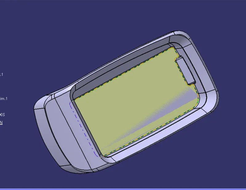
- On analysing the class A surface we can see that it is a kind of rectangular bin made to hold the coins, this bin has walls parallel to the z direction.
- We can also see a hole in one of the bin wall which would require a side core and for that we have to make a separate tooling axis, but we would deal with it in this project.
- On the basic of our analysis we decided to keep the direction of the tooling axis along the z direction because most of the walls of the class A surface are parallel to the z direction.
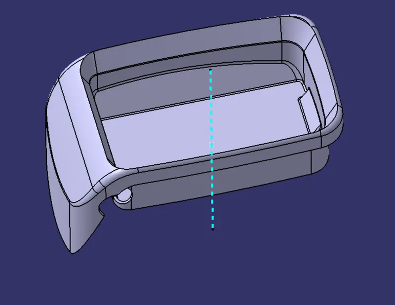
- In order to create our tooling axis somewhere in the middle of the model we take the base surface of the rectangular bin and untrim it.
- Then create a point using "on the surface" option and select the untrimmed surface and keep the distance zero. The point will be created somewhere in middle of the surface.
- Then create a line using "point direction" option and take the direction along the Z axis.
- The resulting line created is the main tooling axis of the model.
CREATION OF RIBS
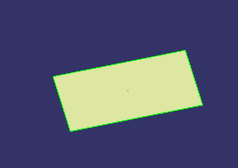
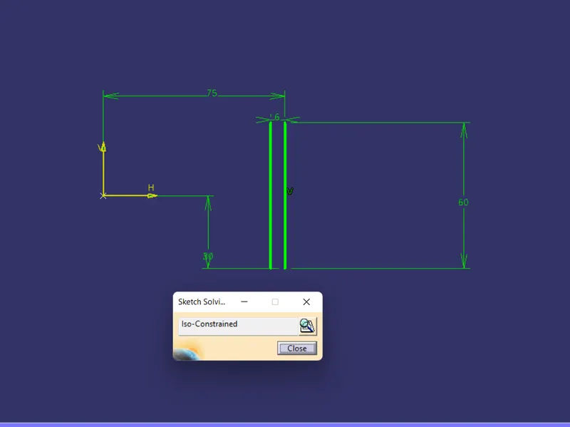
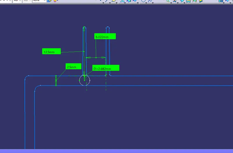
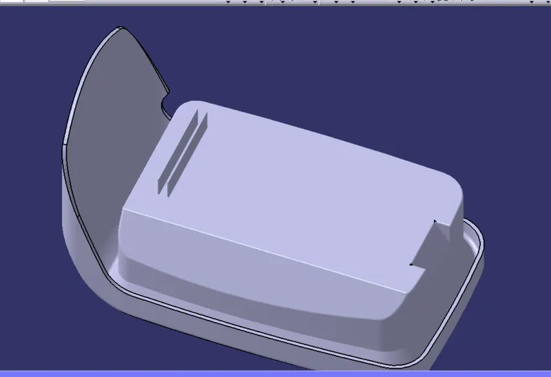
- Create a positoned sketch as shown on the outer bottom surface of the coin holder. create a straight line as shown in the figure below. Right click on the line and choose outside feature.
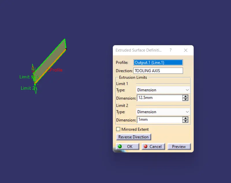
- Extrude the line upto a height equal to 5 times the wall thickness. i.e 2.5*5=12.5mm.
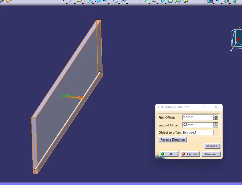
- Thicken the resulting extrude equal to 0.4 times the wall thickness. i.e 2.5*0.5=1mm.
- Add the rib body part to the main coin holder body.
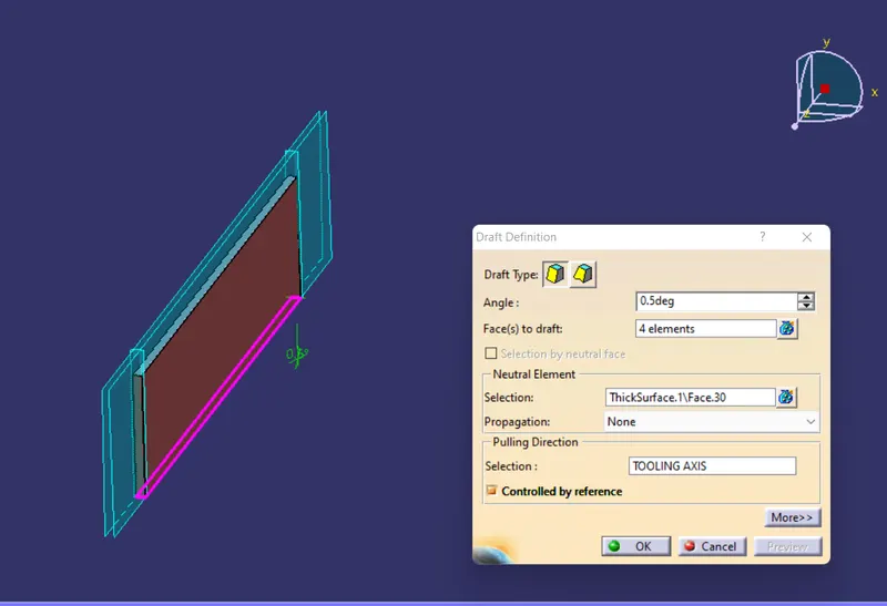
- Give the draft value of 0.5 degrees to each side of the rib.
- Give the fillet value of 0.25mm to all the edges of the rib.
- Create another rib in the same manner as that of the first one.
- Minimum gap maintained between these two ribs should be in a ratio of 1:3 with the height of the rib.
DRAFT ANALYSIS
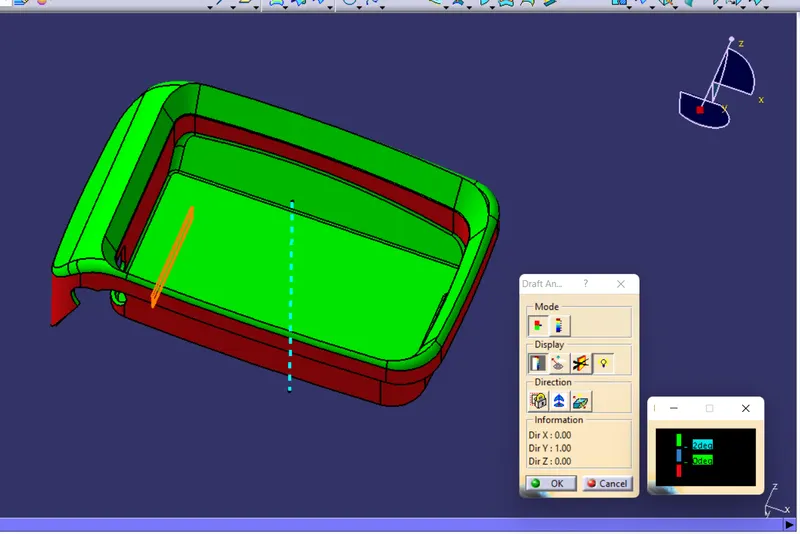
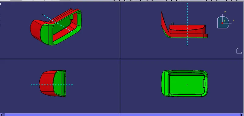
Go to Insert>Analysis>Feature draft analysis.
Click on the compass icon and align the compass along the tooling axis of the coin holder part model.
Click the lock icon and click on the model.
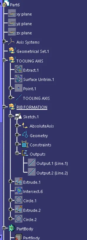
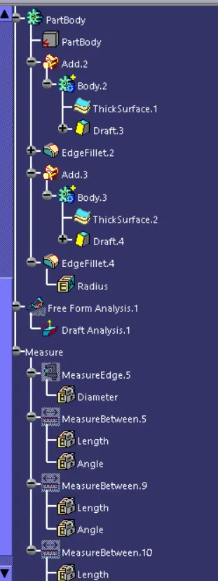
TREE STRUCTURE