Week 8 - Challenge 4 - Coin Holder Design
DESIGN AND DRAFT ANALYSIS OF CENTER CONSOLE COIN HOLDER
OBJECTIVE: The motive of this report is to illustrate the procedures involved in designing a solid model of a center console coin holder in a car using a class A surface as an input and perform draft analysis on this model.
INTRODUCTION: In this report we are going to learn how a Class A surface as an input is utilised to create a solid model according to OEM's standards. Here we will design class B and C surfaces from the given class A surface and joining them altogether to form a closed surface model and finally converting that closed surface into a solid part. Here we will also learn how to perform draft analysis of the model which is followed by most of the OEMs.
DESIGNING METHODOLOGY
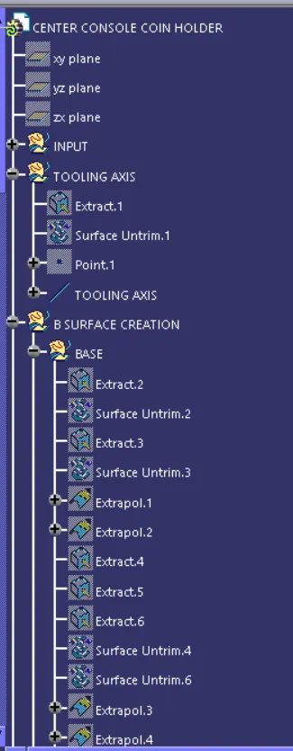
CREATION OF TOOLING AXIS
- For the creation of tooling axis the first thing that we need to do is visual interospection of the class A surface.
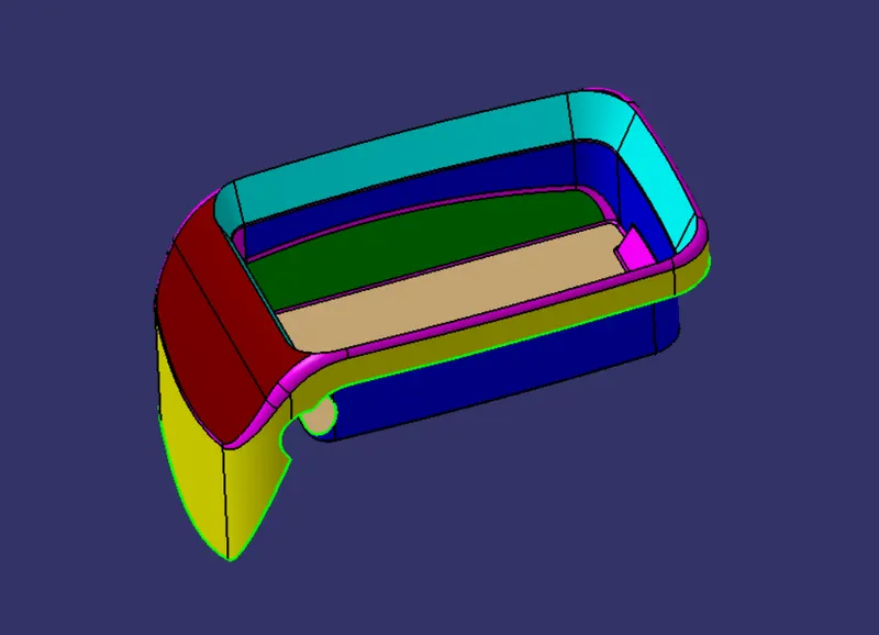
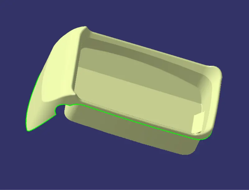
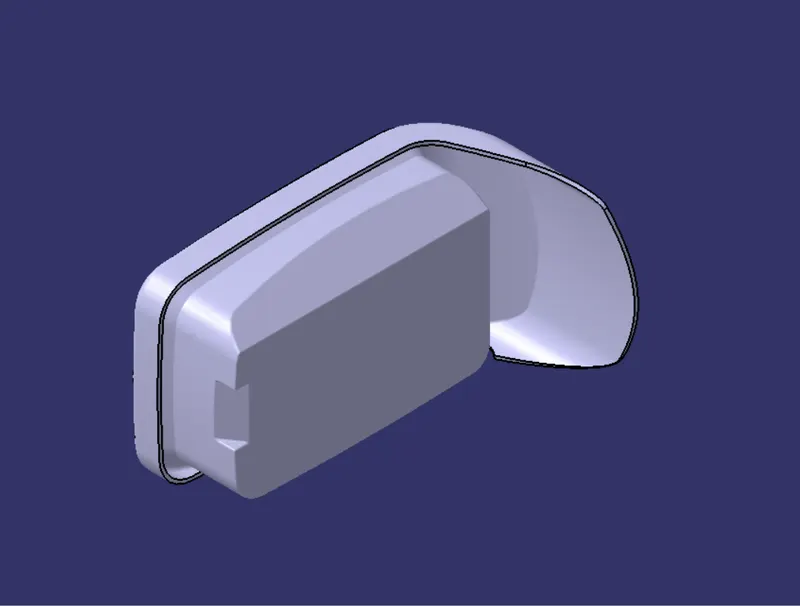
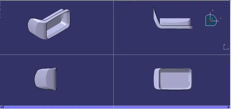
- On analysing the class A surface we can see that it is a kind of rectangular bin made to hold the coins, this bin has walls parallel to the z direction.
- We can also see a hole in one of the bin wall which would require a side core and for that we have to make a separate tooling axis, but we would deal with it in this project.
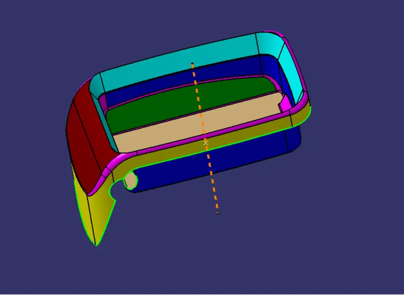
- On the basic of our analysis we decided to keep the direction of the tooling axis along the z direction because most of the walls of the class A surface are parallel to the z direction.
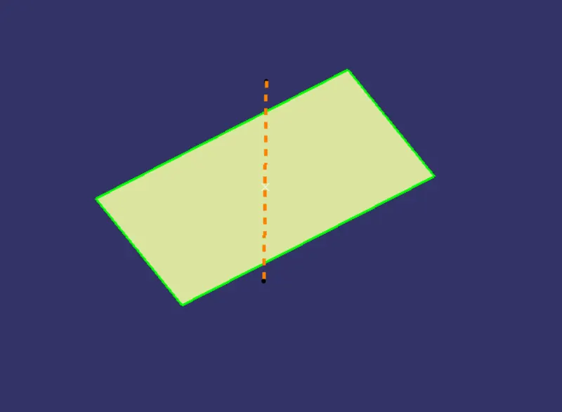
- In order to create our tooling axis somewhere in the middle of the model we take the base surface of the rectangular bin and untrim it.
- Then create a point using "on the surface" option and select the untrimmed surface and keep the distance zero. The point will be created somewhere in middle of the surface.
- Then create a line using "point direction" option and take the direction along the Z axis.
- The resulting line created is the main tooling axis of the model.
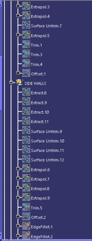
CLASS A SURFACE FORMATION
- Extract all the surfaces of the class A surface and untrim them.
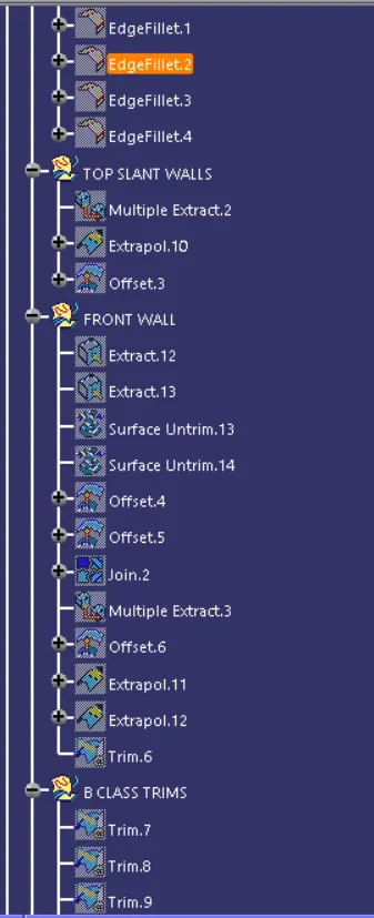
- Divide all the surfaces into four different set of walls i.e side walls, base walls, top slant walls and front walls.
- Use extrapolate command to enlarge all the surfaces so that all of them would intersect with each other.
- Use offset command to offset the side walls, base walls and top slant walls 2.5mm outside the class a surface but in case of front walls we would offset them with the same value but to the inner side of the class A surface.
- Trim the all set of walls with their respective members and the then trim off the resulting entities with each other one by one, the resulting surface we would get is our class B surface.
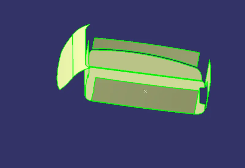
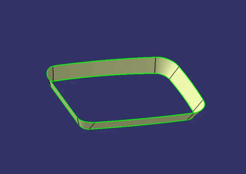
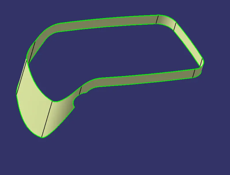
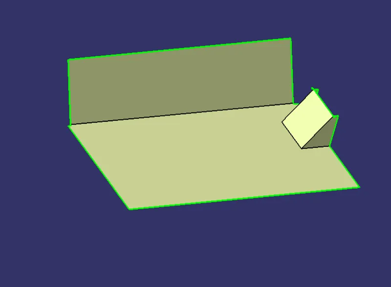
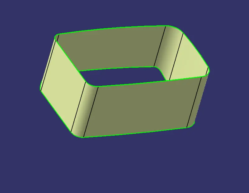
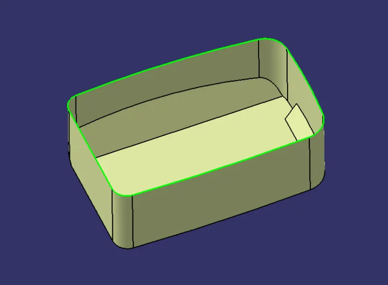
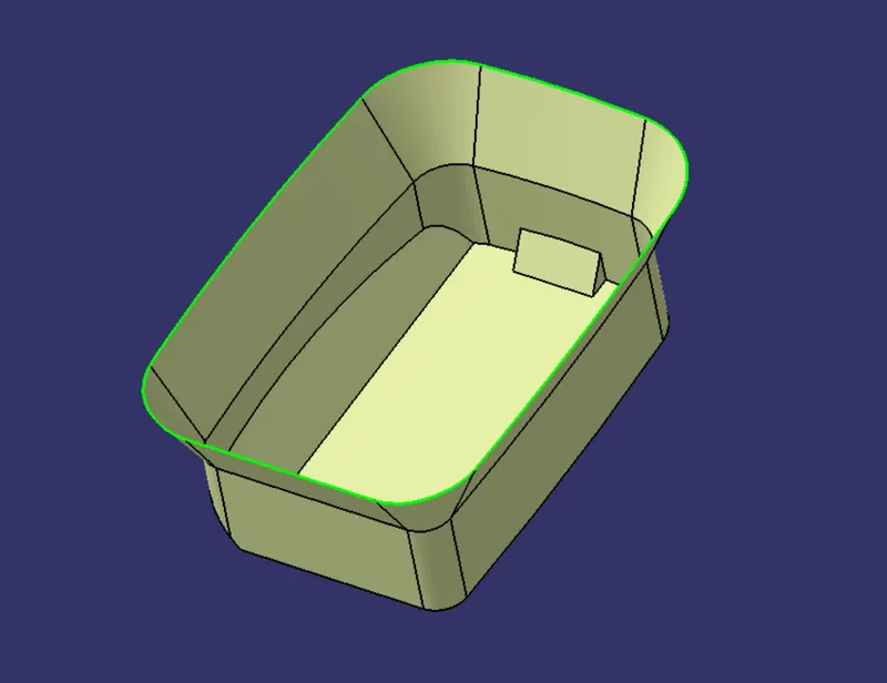
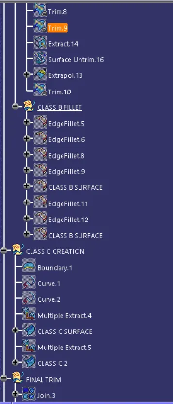
CLASS C SURFACE CREATION
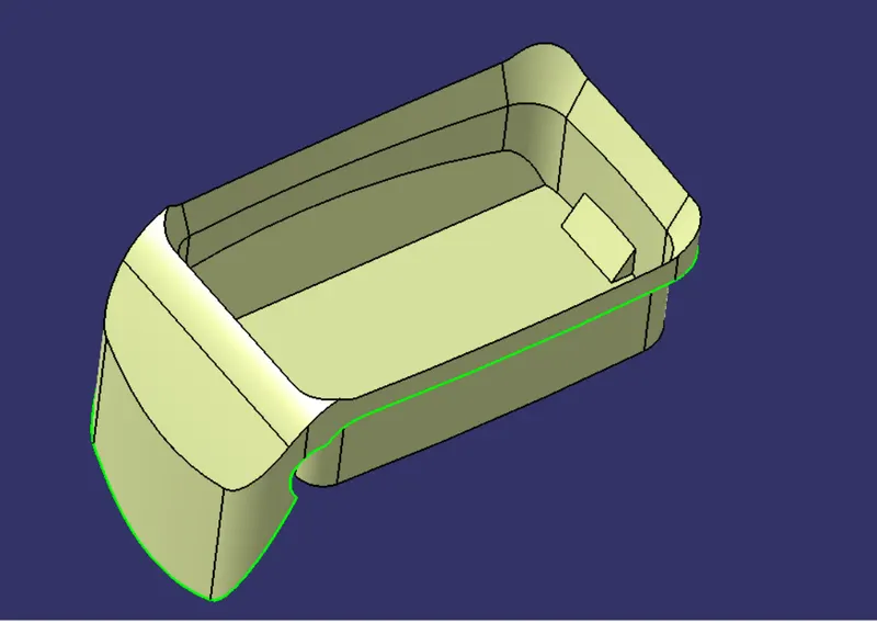
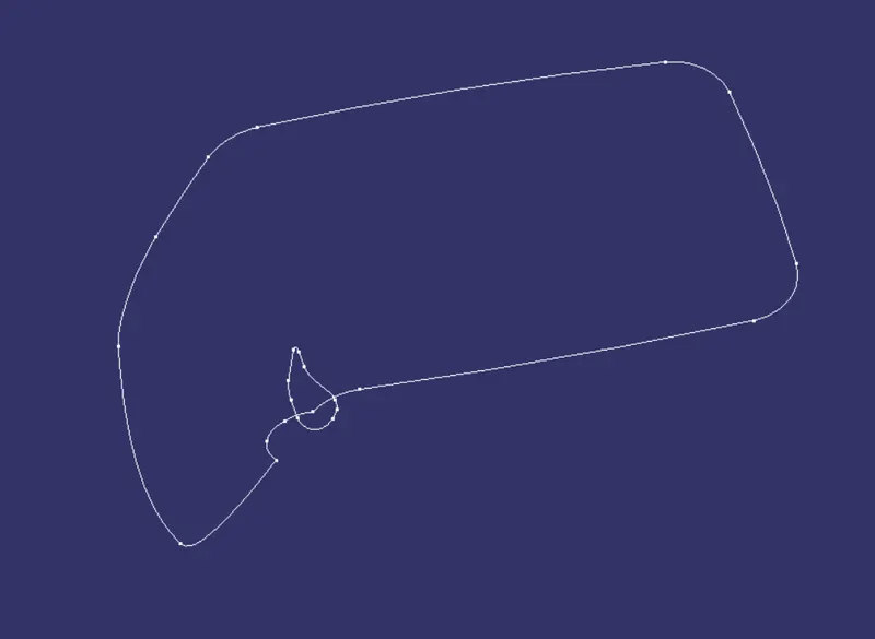
- In order to create the class C surface first we'll use the boundary command on the class A surface, from this we'll get two boundary curves, one for the peripheral boundary of class A surface and the other for the hole in it.
- Use disassemble command to divide the boundary into two domain curve.
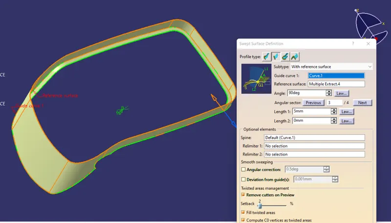
- Apply multiple extract command to extract the set of surfaces which are the part of the outer periphery of the class A surface.
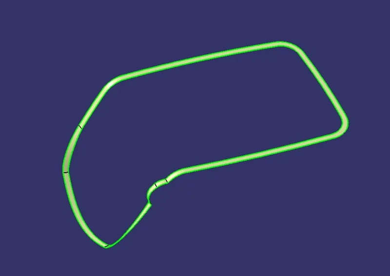
- Use sweep command with "with reference surface" option and for the profile select the first disassembled curve, put the draft angle to zero. The resulting sweep created would be the class C surface.
- In the same manner create the class C surface for the hole.
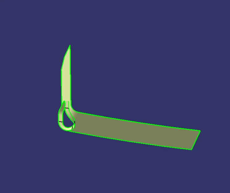
FORMATION OF THE CLOSED SURFACE
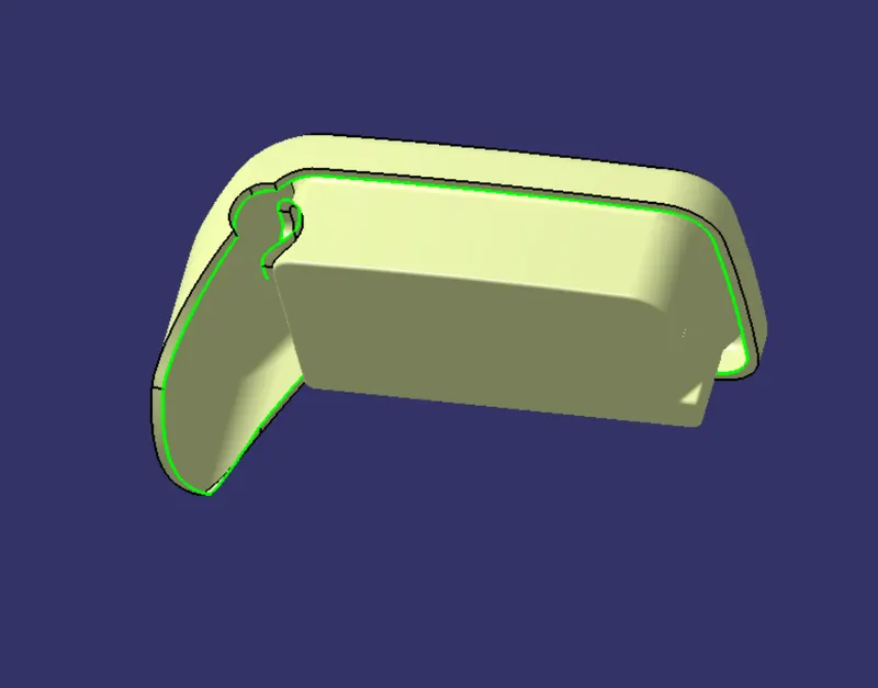
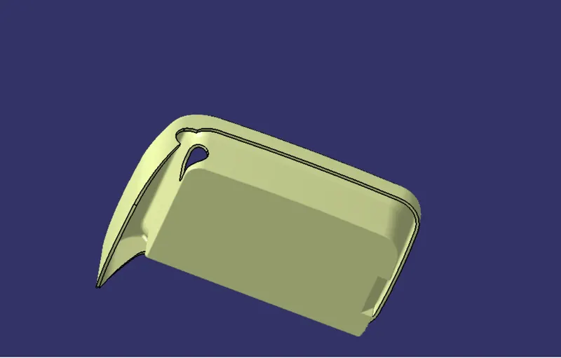
Now we have all the surfaces i.e class A, class B and class C surface, so in order to create the closed surface or shell model of the coin holder first we join the class A surface with class C and then we simply use the trim command for one last time to trim off the resulting join with class B surface. The resulting entity that we get is our closed surface model of the coin holder.
FORMATION OF SOLID PART BODY
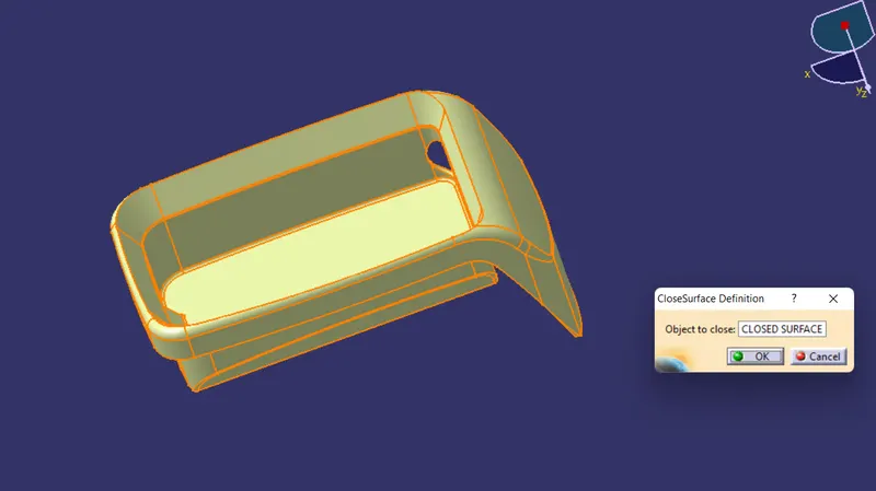
To create the solid body out of the closed surface we'll go the part design workbench and then we'll use the closed surface command to fill the shell and the resulting body is our solid part body.
DRAFT ANALYSIS
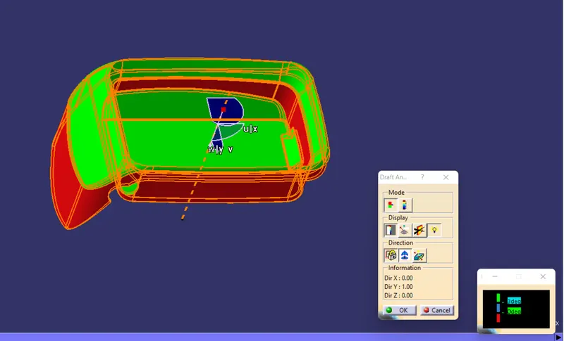
Go to Insert>Analysis>Feature draft analysis.
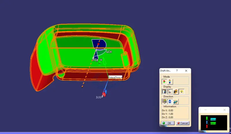
Click on the compass icon and align the compass along the tooling axis of the coin holder part model.
Click the lock icon and click on the model.
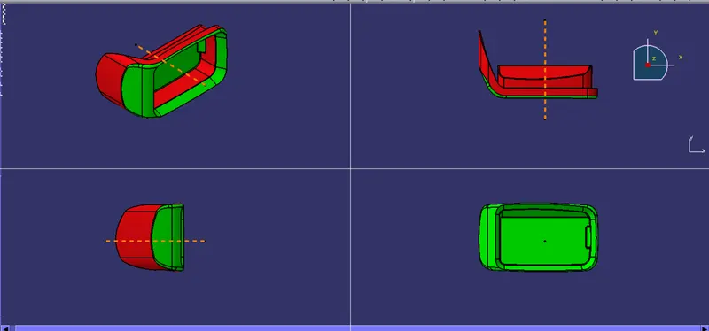
CONCLUSION OF DRAFT ANALYSIS:
As we can see in the draft analysis all the side walls parallel to the tooling axis direction are red in colour which means they have a draft angle of either zero degrees or less than that. The reason for this is the class A surface itself, in class A surface no or zero draft is given on the side walls by the class A designer.
We as a class B designer can't make any changes on class A surfaces so in order to maintain the uniform thickness of the model we also have to give zero draft value to the class B surface.
As we can see that the model is not feasible for tooling process so we can send this feedback to the class A designer and ask him to change the class A surface according to our needs.
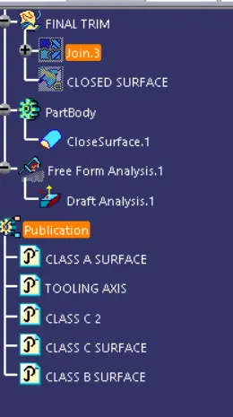
FEATURE TREE: