Radar Mast & Final Assembly of Yacht
3D MODELLING AND RENDERING OF CRUISING MONK YACHT USING SOLIDWORKS
OBJECTIVE
- To prepare the blueprint of cruising monk yacht using images of handmade sketches of all four views of the predator yacht.
- To design all the parts of cruising monk yacht by the help of already prepared blueprint.
- To assemble all the part models into a complete 3d model of cruising monk yacht.
- Rendering the whole assembly of the cruising monk yacht in different backgrounds and environments.
INTRODUCTION
The whole and sole purpose of this report is to elucidate the reader about the general approach and methodology involved in designing a component using a 3d modelling tool like SOLIDWORKS it also includes the rendering of the model which helps it gives a realistic appearance.
Here we have taken the cruising monk yacht as conceptual model in order to carry out the designing process, this report discusses the procedures involved in creating a 3d model using various features of SOLIDWORKS. Apart from this, different special features and commands have been discussed in this report with the help of which we would be able be acomplish the tedious task of designing the predator yacht in a very swift and easy manner.
METHODOLOGY/APPROACH
The general approach to create a 3d model especially with complex structures like the cruising monk yacht, a phased manner is followed which is shown in the flow chart below:
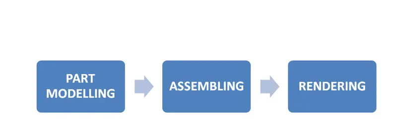
- PART MODELING: It is a modeling interface provided by SOLIDWORKS where we design the models of the individual parts of a mechanical structure such as yacht in this case, without part modeling we can’t create good model prototypes because it won’t create the exact simulation of the desired prototype which would not allow us to carry out different analysis on the prototype mostly related to kinematic motion.
- ASSEMBLING: it is another interface provided by SOLIDWORKS which allows us to assemble all the individual parts in order to form the whole assembly as the predator yacht in this case.
- RENDERING: rendering is the final procedure of the designing process which involves giving realistic views to the part models or the final assembly model. Rendering includes setting up camera view, creating background and environment, providing necessary lightings and applying final render.
METHODOLOGY
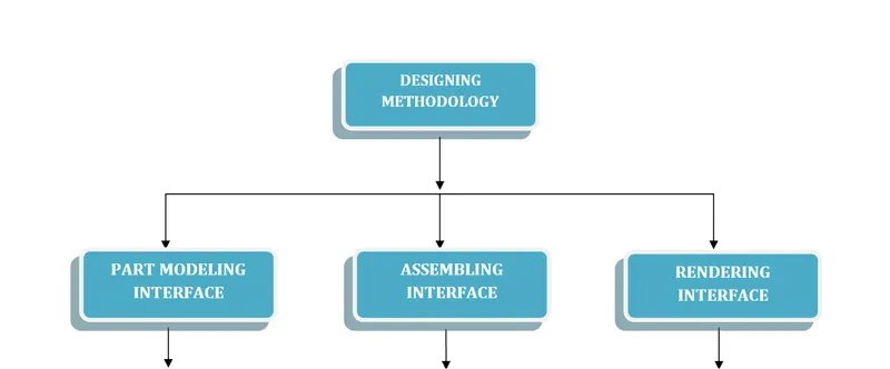
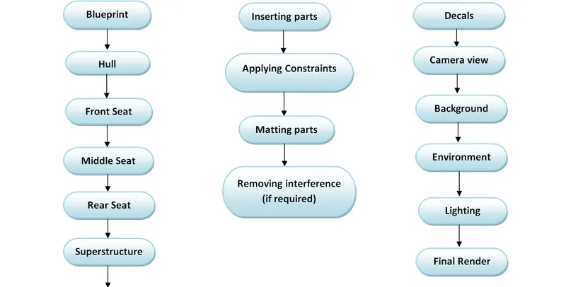
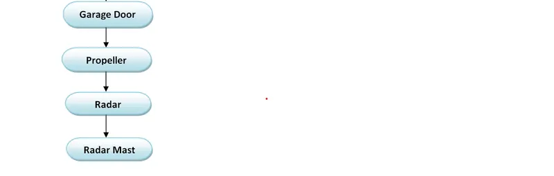
In modeling the cruising monk yacht we followed the bottom to top approach i.e. starting off with designing the bottom portion of the yacht and ending up with the top portion of the yacht. The designing methodology for preparing predator yacht model is explained with the help of flow chart diagram as shown below.
TOOL DESCRIPTION:
In designing process of cruising monk yacht various modeling tools are being used in order to carve out the desired geometry. All these tools have been categorized as follows:
- Sketching tools
- Solid modeling tools
- Surface modeling tools
- Rendering tools
- Miscellaneous tools
SKETCHING TOOLS:
- Line: One of the basic command for sketching a line in any particular plane, it is used in creating almost all kinds of geometries, mostly in creating solid bodies having some linear geometry such as radar model.
- Construction line: construction line is nothing but a dashed line, it is very useful in terms of taking a reference such as to give dimension to any sketch entity with respect to origin, creating a reference plane, conducting revolve,creating mirrored object and in many other operations.
- Circle/Ellipse: This command is used for generating a circle or an ellipse which can be used in creating bodies having cylindrical, elliptical or dome shaped geometry such as railings of the hull.
- Square/Rectangle: In order to generate a solid body which is having rectangular or square cross-section we need to create a rectangle or square as a sketch entity through the square or rectangle command.
- Spline: spline command is very useful when we want to create curves of some definite shape. This command allows us to generate curved surfaces with desired curvature which proved to be very helpful in generating side surfaces of hull and superstructure.
- Arc: we can use this tool if we want to create partially circular entities in our sketches which can lead to the creation of some partially rounded objects.
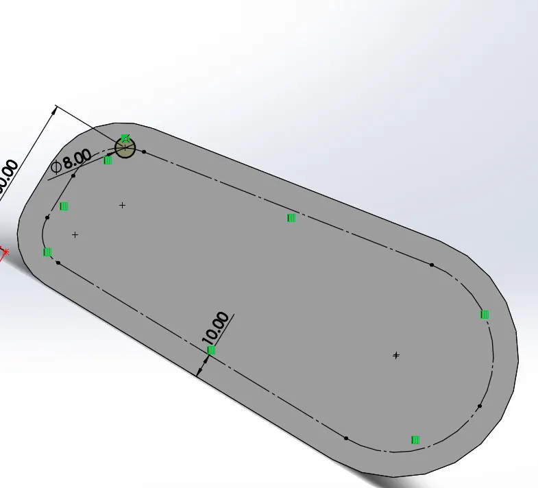
- Offset: there is a frequent requirement of offset command in any modeling process this allows us to copy any sketch entity with some definite offset, we can use offset in many ways in our designing process, creating a hollow object is one of the example.
- Convert entities: A very useful feature when you need the same sketch or sketch entity that you had already created in some other plane, so we can imitate all such entities in a new plane which should be parallel to that of previous plane, otherwise we can see changes in parameters and orientation of sketch entities. Any changes in the base or primary sketch entities will be automatically reflected to the converted sketch entities.
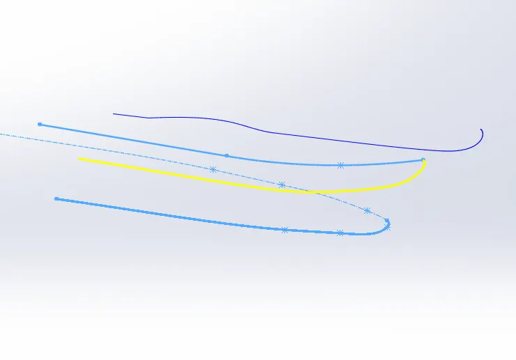
- Project curve: project curve is a feature which allows us to create a curve or a line segment oriented in a three dimensional space. Project curve command does it by intersecting the projection of two separate sketches created in their respective planes. This feature is being used in our designing process a many times such as in creating the curved edges and surfaces of hull and superstructure.
PROJECT CURVE:
OFFSET:
HELIX CURVE:
SOLID MODELLING TOOLS:
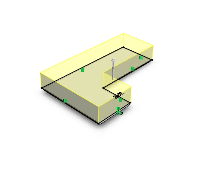
- Extrude Boss/Base: This is one of the most commonly used commands in solidworks which generates solid bodies out of already made sketches (largely 2D) and the path of extrusion is generally linear. There are various methods available to us for applying this feature such as blind, through all etc. and we can apply them according to the need.
- Lofted Boss/Base: It generates a solid body by lofting along a path (guide curve) with the help of two or more profile which determines the cross-section of that lofted solid body.
- Revolve Boss/Base: As the name suggests this feature generates a solid object by revolving a sketch around a reference axis. Using this command we can create fully or partially circular objects such cylindrical or dome like objects.
- Swept Boss/Base: An extruding feature in solid modeling which allows us to create bodies with long wire like geometry. Two basic entities are needed namely profile and path in order to generate a solid body and it is done by sweeping the profile along the path. Generally the profile and path chosen to conduct this operation are majorly a geometric figure i.e. circle and a curved segment.
- Extrude Cut: This feature allows us to cut sections completely or partially out of any solid body this tools proved to be very instrumental when it comes to cut out grooves or slots in any solid object.
- Revolve cut: The functioning of this tool is similar to extrude cut command but instead of cutting in a linear fashion, it cuts the section in a circular path using a profile and this feature is meagerly used in the designing of our predator yacht.
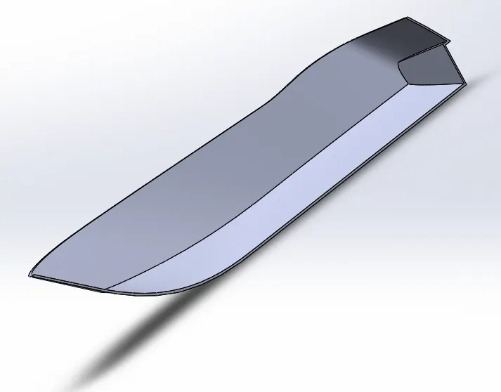
- Shell: This feature converts any pre existing solid body into a hollow shell and also allows us to decide the thickness of this shell. We used shell command to vacant or depress the hull from top in order to give space for superstructure and front, rear and middle seats.
- Combine: while designing a part model we often see a no. of solid bodies being generated in the feature tree but it could be very cumbersome if we want to apply any appearance to the whole part model as a single unit. In this case we can apply combine command which combines all the individual solid entities into a single entity.
- Pattern: We generally deals with some models or prototypes which consists of a large number of identical components arranged in a specific pattern, this command is very useful in such cases, it patterns the features, faces and bodies by taking reference of a base feature, face or body which needs to be replicated a number of times in a specific pattern. There are basically four ways to conduct a pattern operation which are named as linear pattern, circular pattern, curve driven pattern and sketch driven pattern out of these four we have used the sketch driven pattern in radar model.
- Mirror: This command generates the mirror replica of the base body/face/feature. This feature has made our task of modeling the yacht much more easy because we just have to design only half portion of the yacht and the rest of it can be generated through mirroring the that half portion, if hadn’t used this feature the total time consumption in the designing process would have been exactly twice of the actual one.
EXTRUDE BOSS/BASE:
REVOLVE BOSS/BASE:
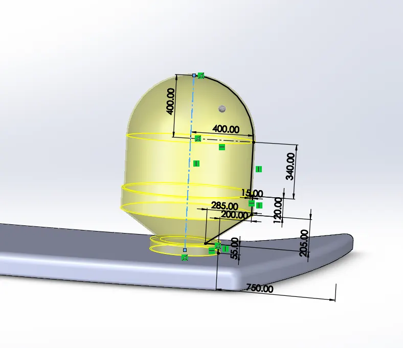
CUT EXTRUDE:
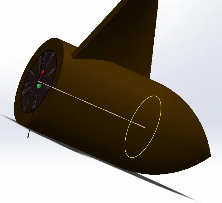
LOFTED BOSS-BASE:
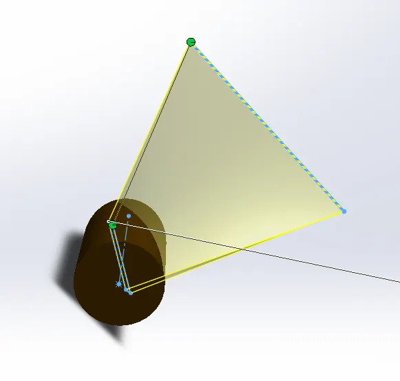
PATTERN:
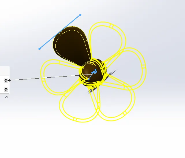
MIRROR:
SHELL:
SURFACE MODELLING TOOLS
- Surface Sweep: surface sweep is a surface modeling tool which enables us to generate surfaces of various kinds of shapes and curvatures, to use this tool we need a reference profile and a path or guide curve through which the profile would be swept.
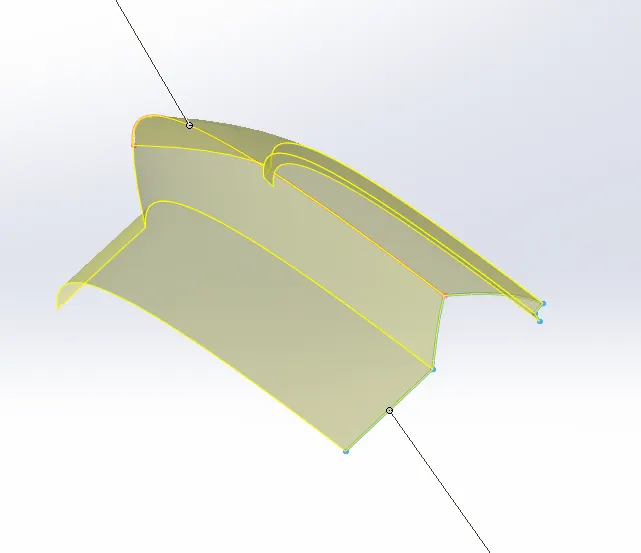
- Surface Loft: The surface loft tool creates a shape by making transitions between multiple profiles and guide curves. This tool is very valuable for modeling complex surfaces such as the top and side surfaces of the hull and superstructure.
- Boundary Surface: The boundary surface tool lets you create surfaces that can be tangent or curvature continuous in both directions (all sides of the surface).when it comes to complex geometry surfaces this feature gives much more good results than the lofted surface tool.
- Extend Surface: This feature is performed to extend the edges of any already created surface upto a definite distance.
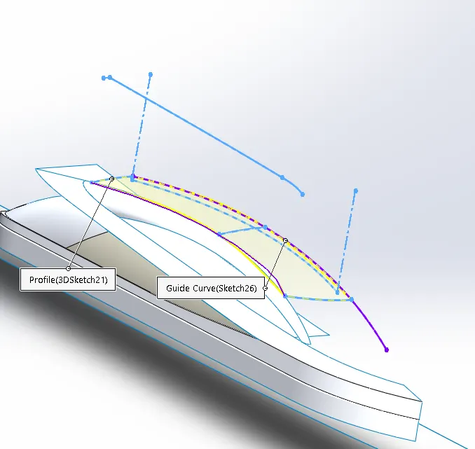
- Ruled Surface: This operation is similar to extend surface tool but ruled surface gives us some extra options to extend the surface in several different manner. We can insert a ruled surface along the edges of a pre existing surface through various options available such as tangent to surface, normal to surface, tapered to vector and perpendicular to vector or sweep.
- Move/copy surface: using this command we can move or copy pre existing surfaces by taking reference about a plane or a sketch.
- Mirror surface: This feature is exactly similar to mirror tool in solid modelling interface where the surface object is replicated as a mirror image of the parent surface this mirrored object is created about a refrence plane or a centerline of the object.
- Surface knit: In the process of surface modeling it is commonly observed that there is some gap formation between the adjacent edges of the surfaces. To combine all such surfaces into a single surface body we use surface knit command which removes all the gaps present between the surfaces. This feature has an additional function namely “try to convert into solid” its function is to convert the surface body into solid body which is only possible if the knitting operation is done properly. Surface knit operation has been frequently used in the designing process of our yacht model.
- Surface trim: surface trim tool is used to trim intersecting surfaces, the trimming function can be apllied only at the line of intersection of the surfaces. surface trim tool has been very often in the surface modeling of hull, superstructure, rear seat and front seat.
- Surface fill: The filled surface feature constructs a surface patch with any number of sides, within a boundary defined by existing model edges, sketches, or curves, including composite curves.
- Cut Sweep: Cut sweep functionality is similar to cut extrude but the major difference between them is that for cut extrude to perform only profile is needed but in case of cut sweep both profile and guide curve are needed. This tool is used in performing intricate cuts.
SURFACE SWEEP:
SURFACE LOFT:
RULLED SURFACE:
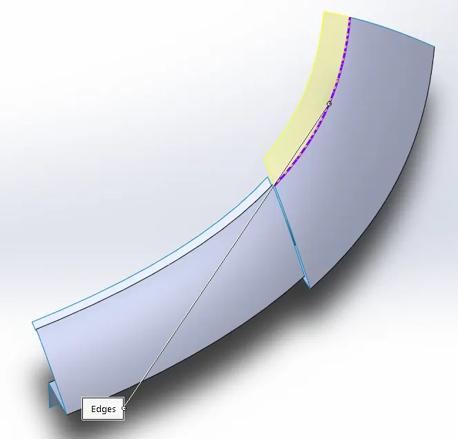
SURFACE FILL:
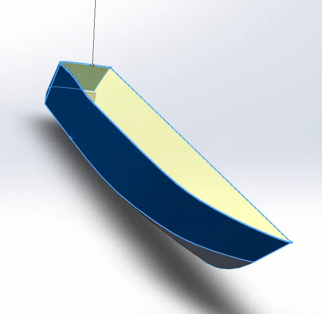
SURFACE TRIM:
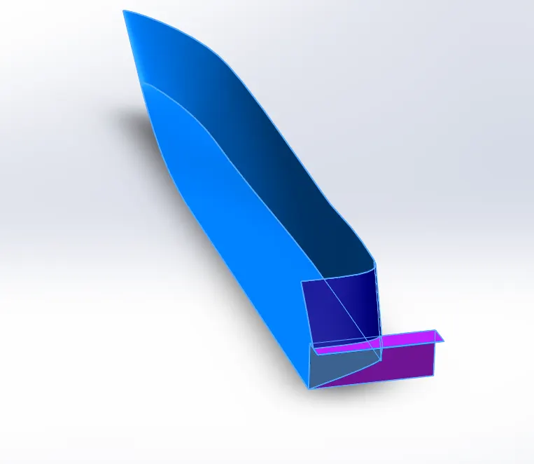
OFFSET SURFACE:
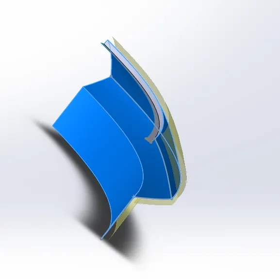
SURFACE EXTRUDE:
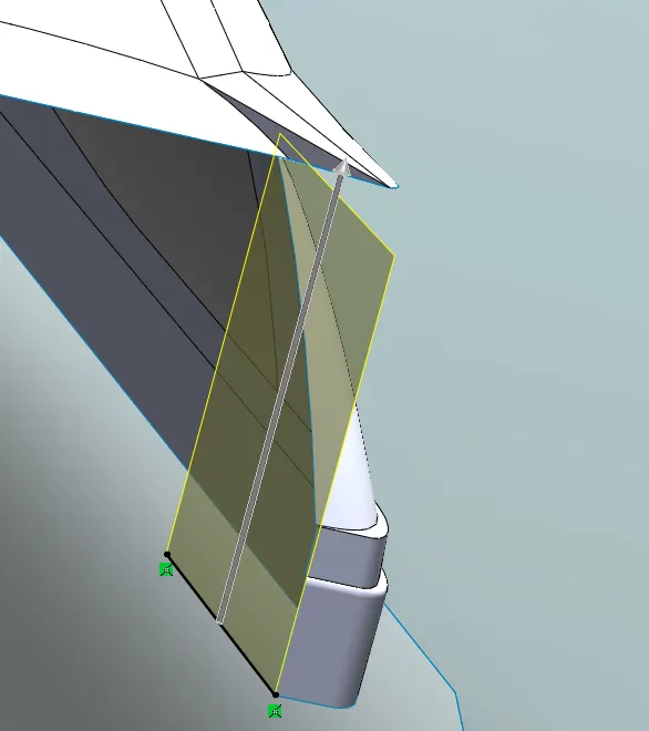
MISCELLANEOUS TOOLS:
- Split: Split tool is used to split the surface or solid bodies into two or more segments, a sketch is needed as a cutting tool to perform the split operation. While performing the split operation we have two options available to us, either we can keep the split out segments or consume the desired split out segments from the surface or body.
- Split line: split line command is used to project a sketch onto a surface generally having curved faces it divides the projected region into a separate face.
- Split point: we can split a sketch entity in two to more entities using this tool, conversly we can delete the split point to rejoin the sketch entities.
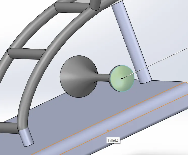
- Fillet/Chamfer: fillet is basically applied to give rounded corners to a body and chamfer is applied to give sloped angled edges to a designed part or body. This feature is frequently used in the modeling process of almost every mechanical component. Here in our model we have been using it to round off every corner and edge.
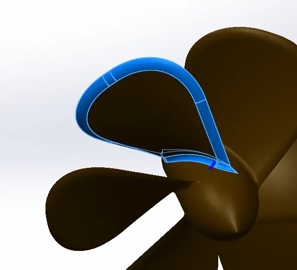
- Dome: Dome command is used to generate a dome shaped structure on the faces. we can directly apply this feature on the model face, elliptical domes are specified for cyclindrical or conical models whereas continous domes are specified for polygonal models. concave domes can also be created by reversing the direction, front seat model has continous domes.
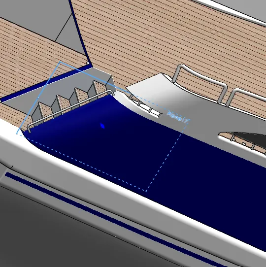
- Reference plane: This feature allows us to create a plane by taking reference from some pre existing planes, sketch entities or faces of the model.
SPLIT:
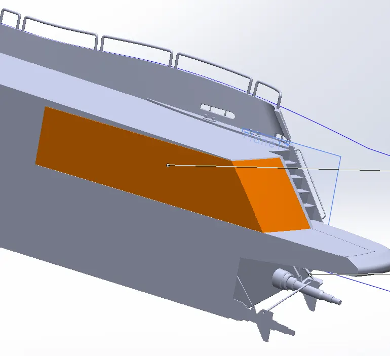
SPLIT LINE:
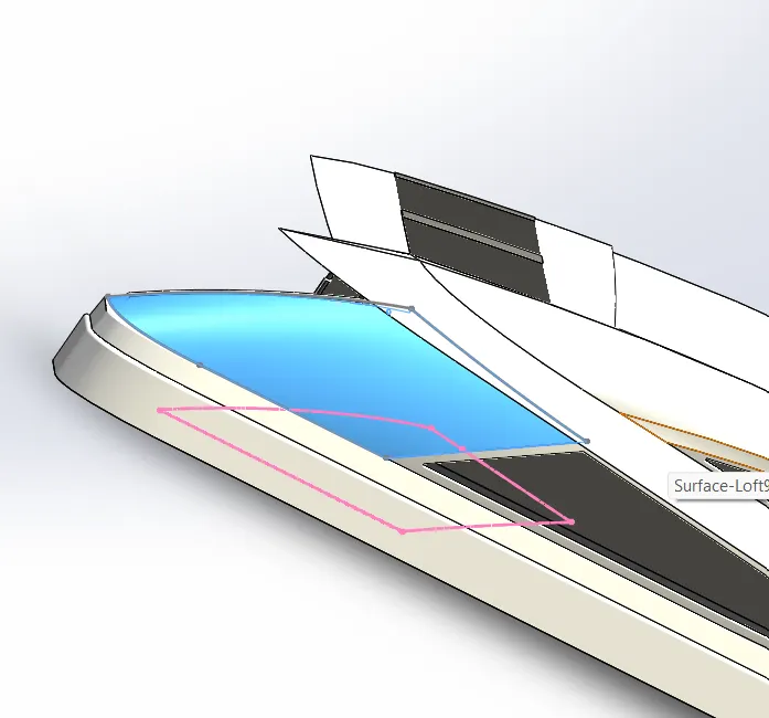
CHAMFER:
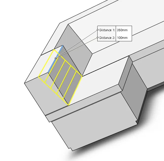
FILLET:
DOME:
REFRENCE PLANE:
RENDERING TOOLS:
- Appearance: This feature gives appearances to the modeled components as per their functionality and material specification. This feature helps in giving realistic look to the final assembly.
- Scenes: It is a render tool which provides a visual backdrop behind a model. In Solidworks they provide reflections on the model. With PhotoView 360 added in, scenes provide a realistic light source, including illumination and reflections, requiring less manipulation of lighting.
- Lights: This feature is used to illuminate the designed model as per our desired point or location in the model. It has several types such as directional lights, spot lights, point light and sunlight.
- Camera: camera is very important feature to carry out final render because the the final render are usually done over camera view. This view is taken out as per requirement of the designer how he wants to present the rendered model.
- PhotoView 360: It is a SOLIDWORKS add-in that produces photo-realistic renderings of SOLIDWORKS models. The rendered image incorporates the appearances, lighting, scene, and decals included with the model.
PART MODELLING DESCRIPTION
BLUE PRINT:
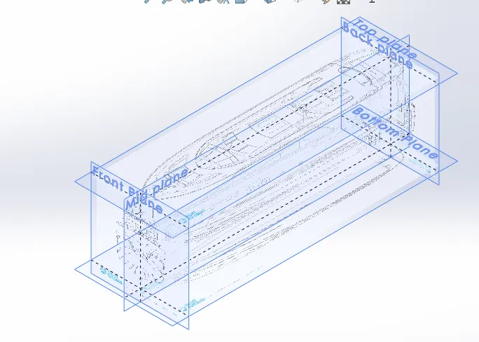
- Blueprint is a photographic print or a handmade sketch on a white sheet which displays the four sided views of any component or structure.
- Blueprint is the foremost thing that needs to be inducted in any designing process because it guides us to prepare a three dimensional model. It gives us the basic idea about how our model is going to be made.
- Blueprint is very helpful when it comes to scale different parts of the model with respect to each other and placing them at the accurate position while assembling.
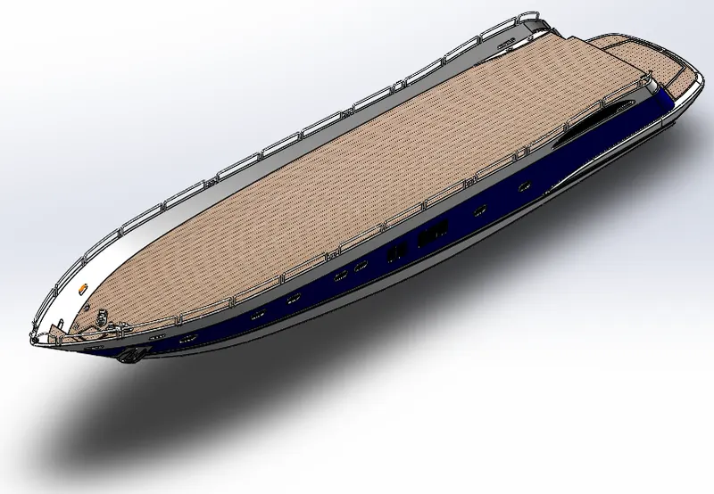
HULL: Hull is the main body part of any water vessel like yacht in this case. It is basically a broad frame like structure which constitutes the bottom most part of the vessel. It carries all other parts of the vessel on its board such as superstructure, front, middle and rear seats and radar mast.
NORMAL VIEW:
RENDERED VIEW: 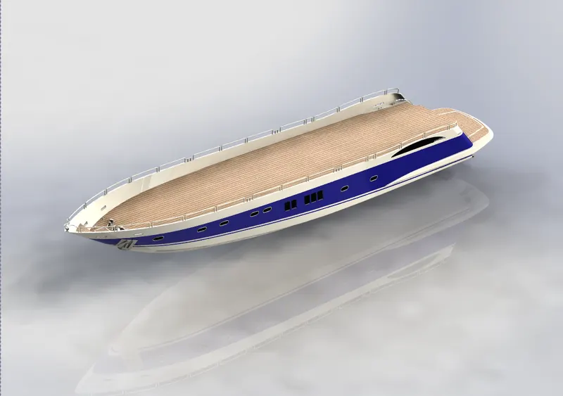
Following tools are used in the modeling process of hull:
SKETCHING TOOLS
- SKETCH PICTURE
- LINE
- SPLINE
- CIRCLE
- RECTANGLE
- ARC
- 3D-SKETCH
- PROJECT CURVE
- SPLIT LINE
- SKETCH PICTURE
SURFACE MODELLING TOOLS
- SURFACE EXTRUDE
- SURFACE REVOLVE
- SURFACE EXTEND
- SURFACE LOFT
- SURFACE KNIT
- SURFACE FILL
- SURFACE TRIM
- OFFSET SURFACE
SOLID MOELING TOOLS
- BOSS-EXTRUDE
- CUT-EXTRUDE
- REVOLVE BOSS
- LINEAR PATTERN
- SWEEP
- SHELL
MISCELLANEOUS TOOLS:
- SPLIT
- COMBINE
- REFRENCE PLANE
- FILLET
- CHAMFER
- DELETE FACE
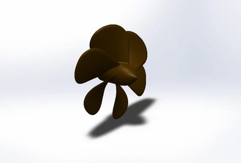
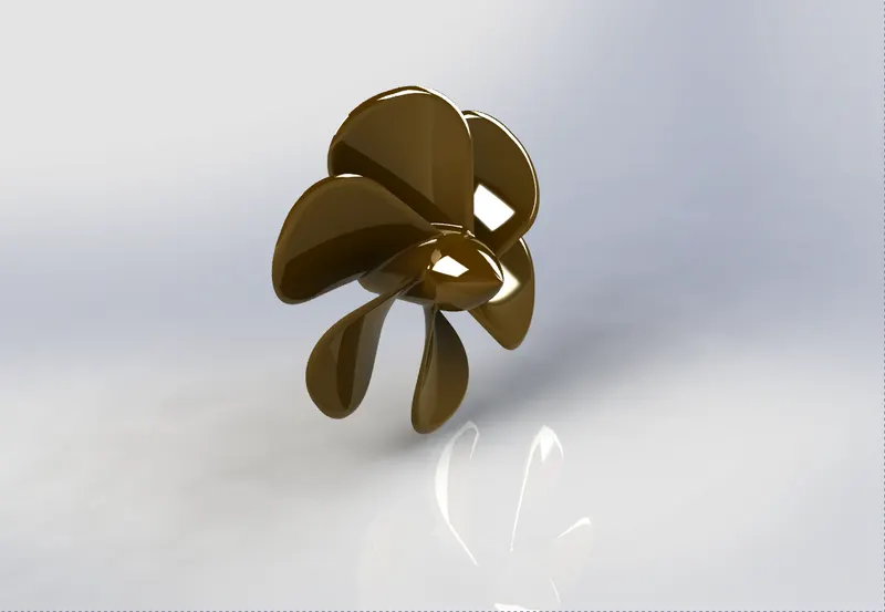
PROPELLER: It is a device with a rotating hub and radiating blades that are set at a pitch to form a helical spiral, when rotated it exerts linear thrust upon a working fluid, such as water or air. The blades are specially shaped so that their rotational motion through the fluid causes a pressure difference between the two surfaces of the blade, which exerts force on the fluid.Most marine propellers are screw propellers with helical blades rotating on a propeller shaft with an approximately horizontal axis.
CAMERA VIEW:
RENERED VIEW:
Following are the tools used in modelling the predator yacht propeller:
SKETCHING TOOLS:
- LINE
- SPLINE
- CIRCLE
- RECTANGLE
- ARC
SOLID MODELING TOOLS:
- LOFTED BOSS
- REVOLVE BOSS
- CUT EXTRUDE
- CIRCULAR PATTERN
MISCELLANEOUS TOOLS:
- FILLET
- REFERENCE PLANE
RADAR: Radar is a vital navigation component in a marine vessel like our predator yacht.The radar system is used to find the correct direction and locate external objects. The signals received by the radar system are transferred to the control room for analysis.The type of radar that we are designing in our predator yacht model is the S Band radar system that use a rotating antena to sweep a narrow beam of microwaves around the water surface surrounding the ship to the horizon, detecting targets by microwaves reflected from them.
CAMERA VIEW:
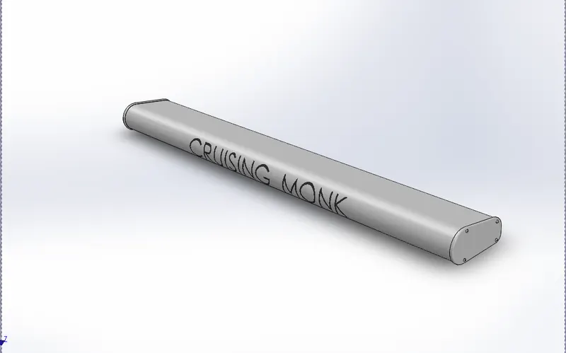
RENDERED VIEW:
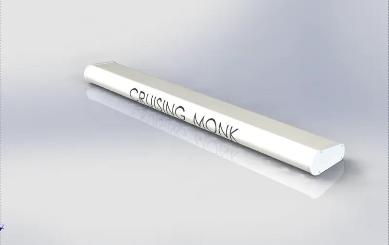
Following are the basic modelling tools used in designing this radar:
SKETCHING TOOLS:
- LINE
- SPLINE
- CIRCLE
- RECTANGLE
- ARC
- OFFSET
- CONVERT ENTITY
SOLID MODELING TOOLS:
- EXTRUDE BOSS/BASE
- CUT EXTRUDE
- SKETCH PATTERN
- MIRROR
MISCELLANEOUS TOOLS:
- FILLET
- SPLIT LINE
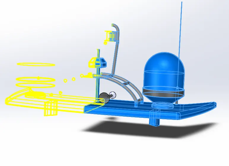
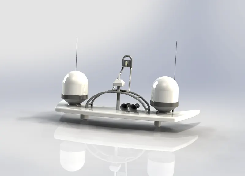
RADAR MAST: The radar system is the largest piece of the electronic equipment, and the radar antenna is located on top of the mast.A mast system is composed mainly of supporting frames,a circular base plate, radar, and an antenna. The base plate is stiffened by six aluminum tubes that are fixed on the supporting frames. The supporting frames are fixed on the upper deck of the ship. The radar and antenna are fixed
on top of the base plate. The weight of the radar and antenna is supported by the base plate.There is an antenna frame to hold the antenna. This frame is sitting between the base plate and the antenna.
CAMERA VIEW:
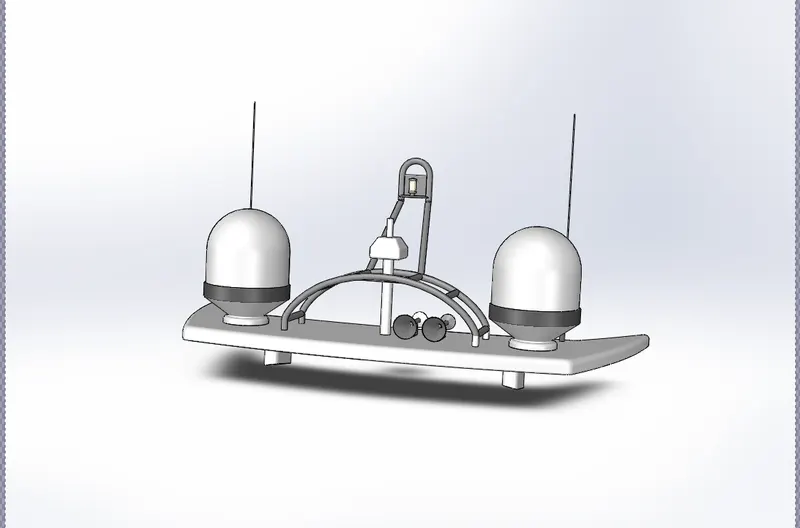
RENDERED VIEW:
SKETCHING TOOLS:
- LINE
- SPLINE
- CIRCLE
- RECTANGLE
- ARC
- OFFSET
- CONVERT ENTITY
- PROJECT CURVE
SOLID MODELING TOOLS:
- EXTRUDE BOSS/BASE
- REVOLVE BOSS/BASE
- SWEEP BOSS/BASE
- MIRROR
MISCELLANEOUS TOOLS:
- FILLET
- CHAMPHER
- REFERENCE PLANE
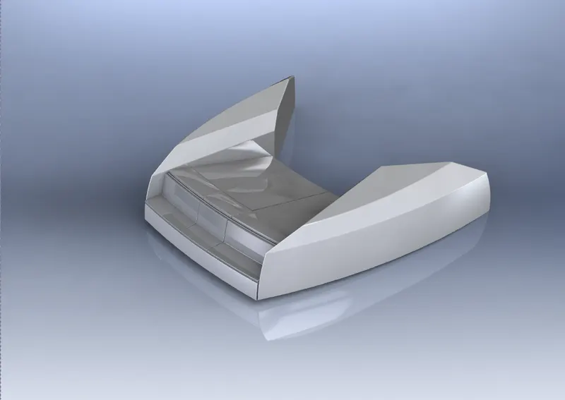
SUPERSTRUCTURE:superstructure literally means to add a construction to an already existing structure. In ships this is the name given to the part of the ship that emerges from the deck. However any mast, sails, any armaments or arsenal are not included in this category.It is designed in a manner, so that, it adds value and hinder the speed and mobility in the least. The superstructure is mostly designed in fashion as well. This is because it is the most easily visible part of the predator yacht, in fact it is the identification of our yacht model, and that is why we have tried our best to provide it with a unique identity.
CAMERA VIEW:
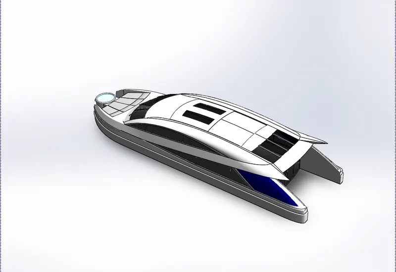
RENDERED VIEW:
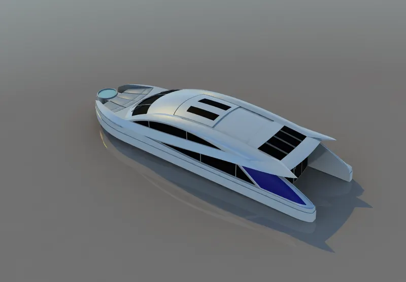
Following are the various tools used in the modeling process of superstructure:
SKETCHING TOOLS
- SKETCH PICTURE
- LINE
- SPLINE
- CIRCLE
- RECTANGLE
- ARC
- 3D-SKETCH
- PROJECT CURVE
- SPLIT LINE
SURFACE MODELLING TOOLS
- SURFACE EXTRUDE
- SURFACE SWEEP
- RULLED SURFACE
- SURFACE EXTEND
- SURFACE LOFT
- SURFACE KNIT
- SURFACE TRIM
- OFFSET SURFACE
- THICKEN SURFACE
SOLID MOELING TOOLS
- BOSS-EXTRUDE
- CUT-EXTRUDE
- REVOLVE
- SWEEP
MISCELLANEOUS TOOLS:
- SPLIT
- COMBINE
- REFRENCE PLANE
- FILLET
- CHAMFER
- DELETE FACE
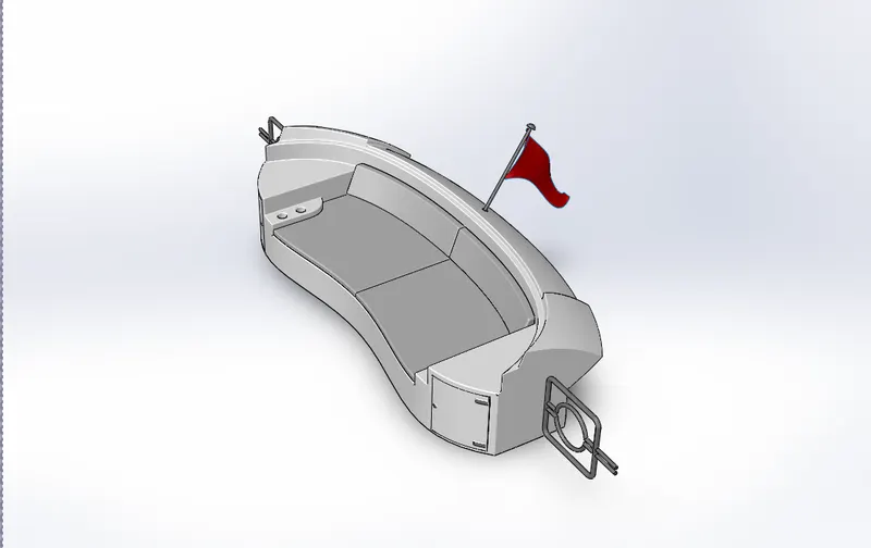
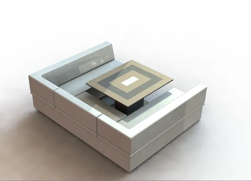
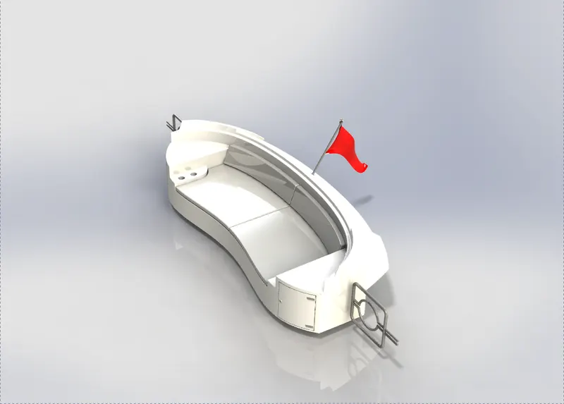
FRONT SEAT/MIDDLE SEAT/REAR SEAT: Front, middle and rear seats are the the sitting arranangment mounted over the deck positioned in the front, mid and back portion of the yacht. In addition, contouring, backrest angle, proper dimensions, seat height, shock absorption, cushioning, and breathability, are some of the factors that we took in matter in order to design these seat models.
CAMERA VIEW:
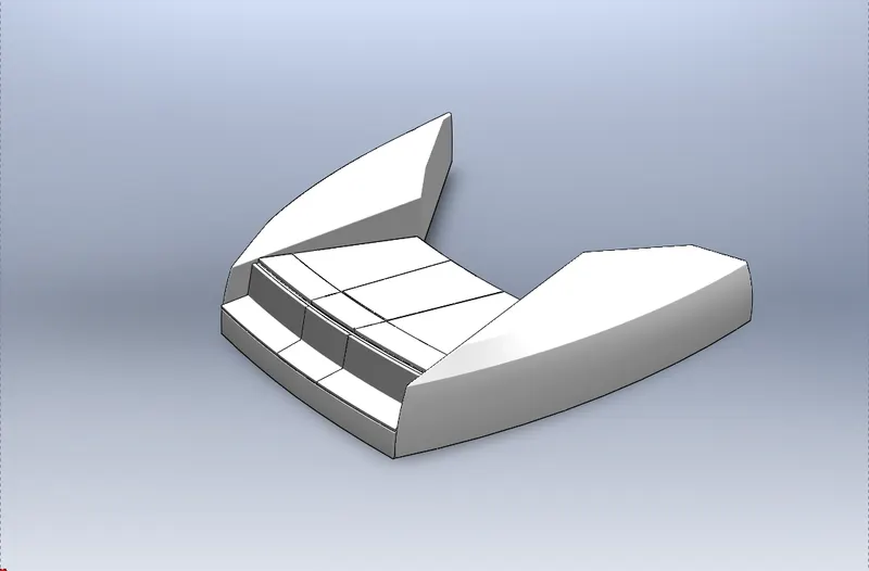
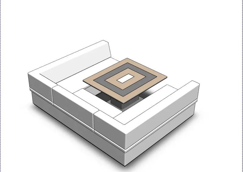
RENERED VIEW:
following are the tools used in designing all three seats:
SKETCHING TOOLS
- SKETCH PICTURE
- LINE
- SPLINE
- CIRCLE
- RECTANGLE
- ARC
- 3D-SKETCH
- PROJECT CURVE
- SPLIT LINE
SURFACE MODELLING TOOLS
- SURFACE EXTRUDE
- SURFACE SWEEP
- RULLED SURFACE
- SURFACE EXTEND
- SURFACE LOFT
- SURFACE KNIT
- SURFACE TRIM
- OFFSET SURFACE
SOLID MOELING TOOLS
- BOSS-EXTRUDE
- CUT-EXTRUDE
- SWEEP
- REVOLVE
MISCELLANEOUS TOOLS:
- SPLIT
- COMBINE
- REFRENCE PLANE
- FILLET
- CHAMFER
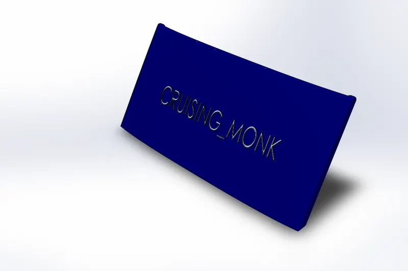
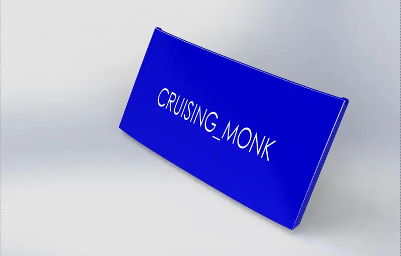
GARAGE DOOR: It is the door of the garage of cruising monk yacht model, here we have designed it as a replica model of top higned hydraulically operated door. It is shaped according to the yacht construction,here we have designed it in a shape of flate rectangular panel as seen in the pictures below.
CAMERA VIEW:
RENDERED VIEW:
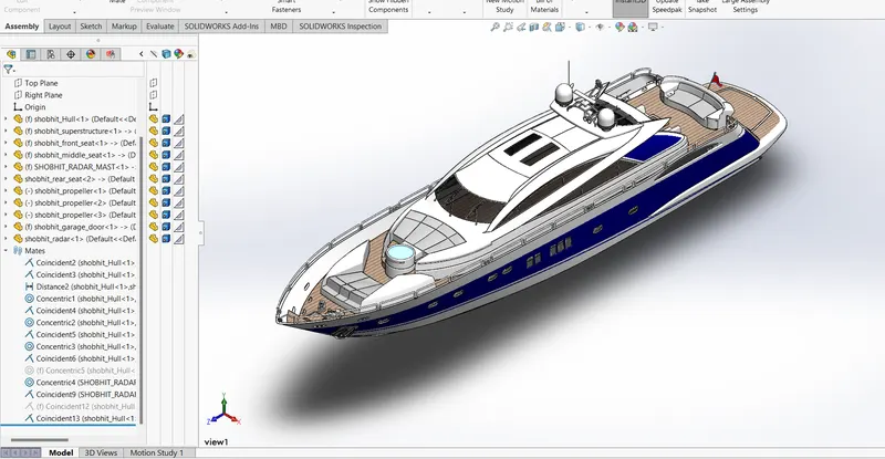
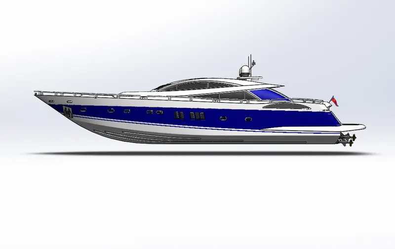
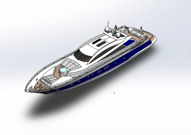
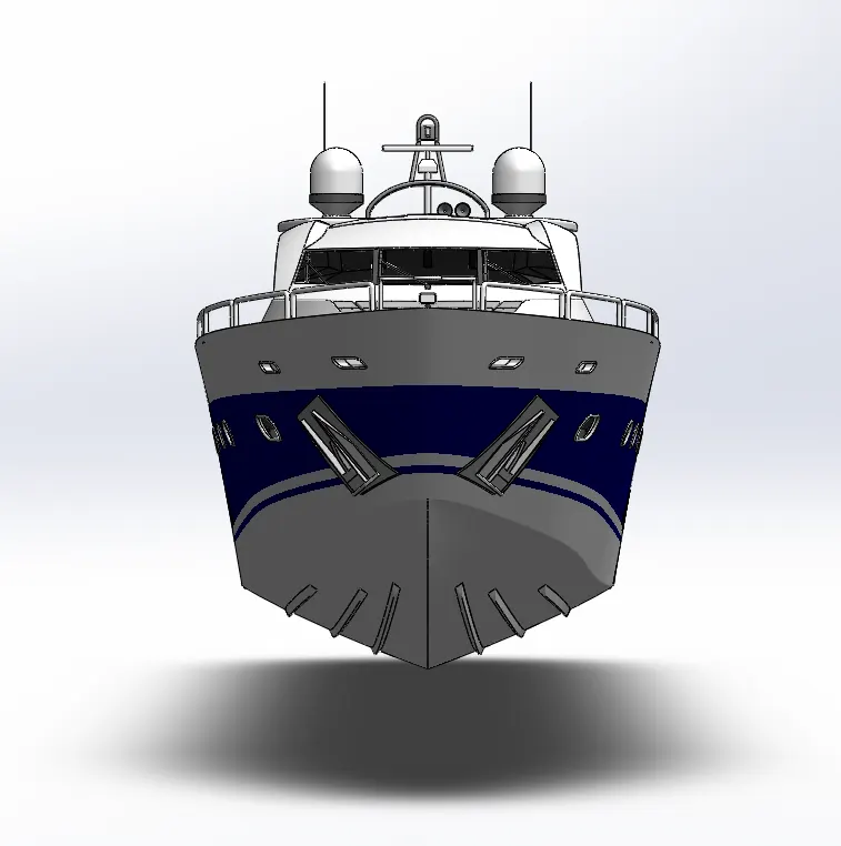
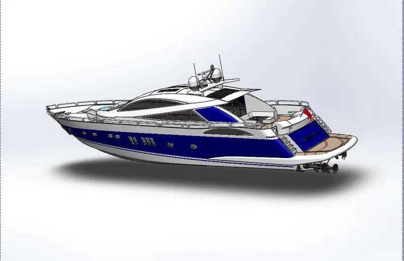
ASSEMBLY:An assembly is a collection of related parts saved in part file documents into assembly document with .sldasm file extension.The components in an assembly are defined in relation to each other using assembly mates. You attach the assembly components using various types of mates such as coincident, concentric, and distance mates. For example, the faucet handle components are mated to the faucet base component using concentric and coincident mates. The mated components create the spigot subassembly. Later, you include this subassembly in the main vanity assembly, mating it to the other components in the vanity assembly.
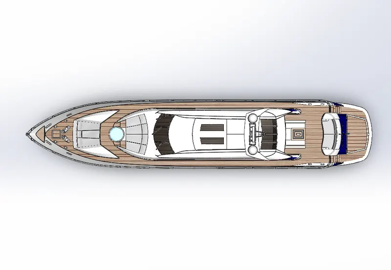
ASSEMBLY TOP VIEW:
ASSEMBLY SIDEVIEW:
ASSEMBLY ISOMETRIC VIEW:
ASSEMBELY FRONT VIEW:
ASSEMBLY CAMERA VIEW:
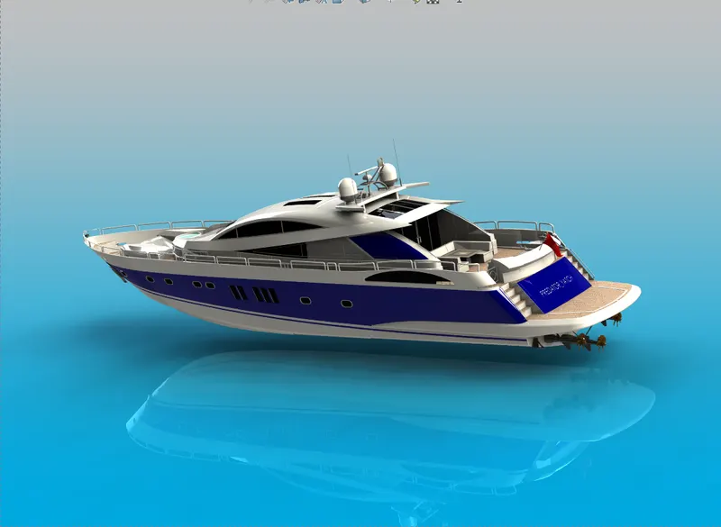
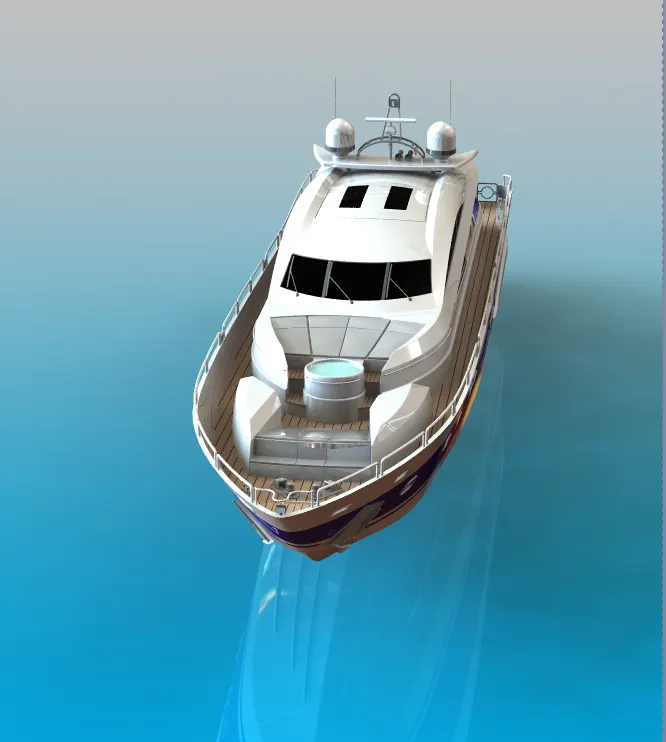
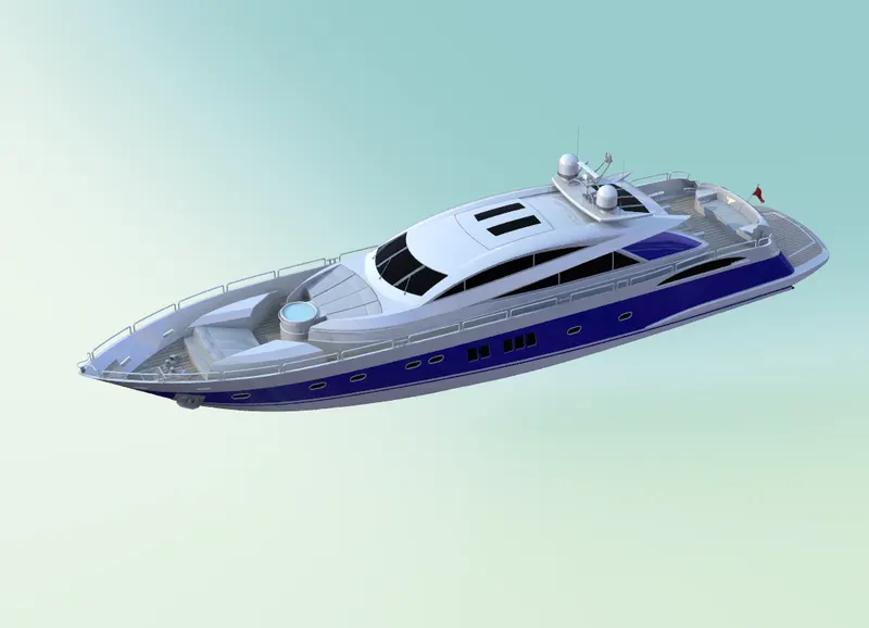
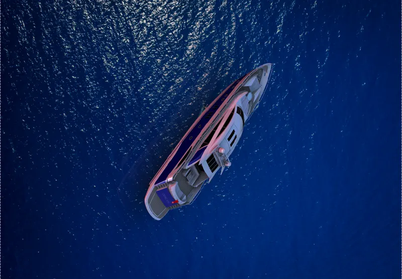
RENDERING:rendering is a representation of two-dimensional computerized wireframe. And this wireframe is given just the perfect shadow, lighting, textures as well as regularly used tools and materials into the frame, to add such features and details in our model we use a SOLIDWORKS add-in called photoview 360, it produces photo-realistic renderings of SOLIDWORKS models. The rendered image incorporates the appearances, lighting, scene, and decals included with the model.
RENDERED IMAGES IN DIFFERENT ENVIRONMENTS:
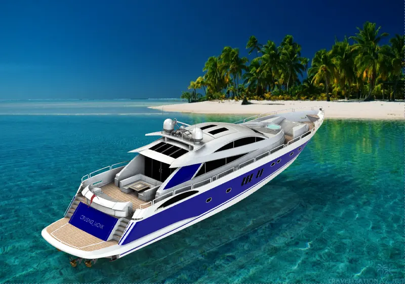
CONCLUSION: Throughout this whole modeling process we learnt a variety of tools in order to perform various operations related to sketching, surface modeling, solid modeling and rendering. We touched almost every aspect of 3d modeling process through this report which elaborated the whole designing process in a brief and precise manner.